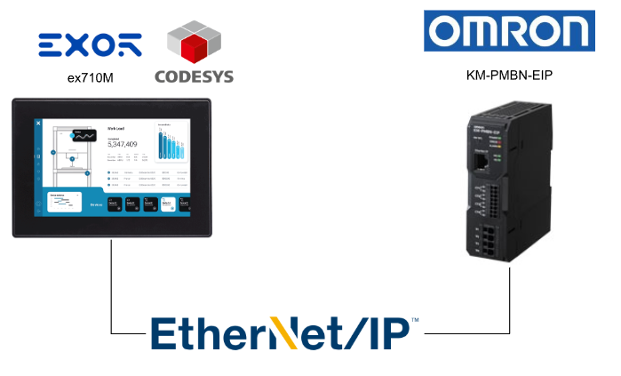
This article connects Omron’s KM-PMBN-EIP power monitor to Codesys Runtime via Ethernet/IP.
Alright, let’s enjoy the FA!
Foreword
Thank you from the bottom of my heart for visiting my technical blog and YouTube channel.
We are currently running the “Takahashi Chris” radio show with Full-san (full@桜 八重 (@fulhause) / X) which I deliver every Wednesday night.
Sharing, not hoarding, technical knowledge
We publish technical information related to factory production technology and control systems for free, through blogs and videos.
With the belief that “knowledge should be accessible to everyone,” we share practical know-how and real-world troubleshooting cases from our own field experience.
The reason we keep it all free is simple: to help reduce the number of people who struggle because they simply didn’t know.
If you’ve ever thought:
- “Will this PLC and device combination actually work?”
- “I’m having trouble with EtherCAT communication—can someone test it?”
- “I want to try this remote I/O, but we don’t have the testing environment in-house…”
Feel free to reach out!If lending equipment or sharing your configuration is possible, we’re happy to verify it and share the results through articles and videos.
(We can keep company/product names anonymous if requested.)
How can you support us?
Currently, our activities are nearly all unpaid, but creating articles and videos takes time and a proper testing environment.If you’d like to support us in continuing and expanding this content, your kind help would mean a lot.
Membership (Support our radio show)
This support plan is designed to enhance radio with Mr Full.
https://note.com/fulhause/membership/join
Amazon Gift List (equipment & books for content production)
Lists equipment and books required for content creation.
https://www.amazon.co.jp/hz/wishlist/ls/H7W3RRD7C5QG?ref_=wl_share
Patreon (Support articles & video creation)
Your small monthly support will help to improve the environment for writing and verifying articles.
https://www.patreon.com/user?u=84249391
Paypal
A little help goes a long way.
https://paypal.me/soup01threes?country.x=JP&locale.x=ja_JP
Just trying to share things that could’ve helped someone—if only they’d known.
Your support helps make knowledge sharing more open and sustainable.
Thank you for being with us.
soup01threes*gmail.com
Technical knowledge shouldn’t be kept to ourselves.
KM-PMBN-EIP
The Omron KM-PMBN-EIP used in this article is a 38mm-wide Ethernet/IP-compatible power monitor designed for global control panels.
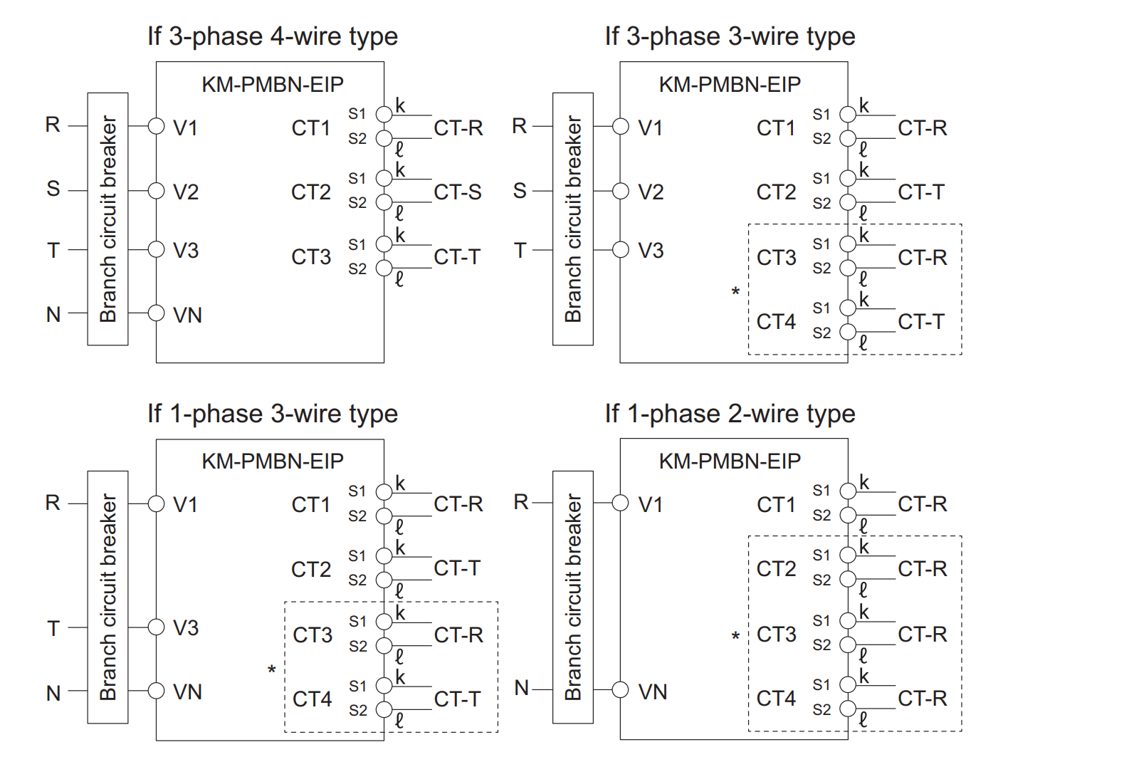
Wiring
This is a wiring example for Omron’s KM-PMBN-EIP.
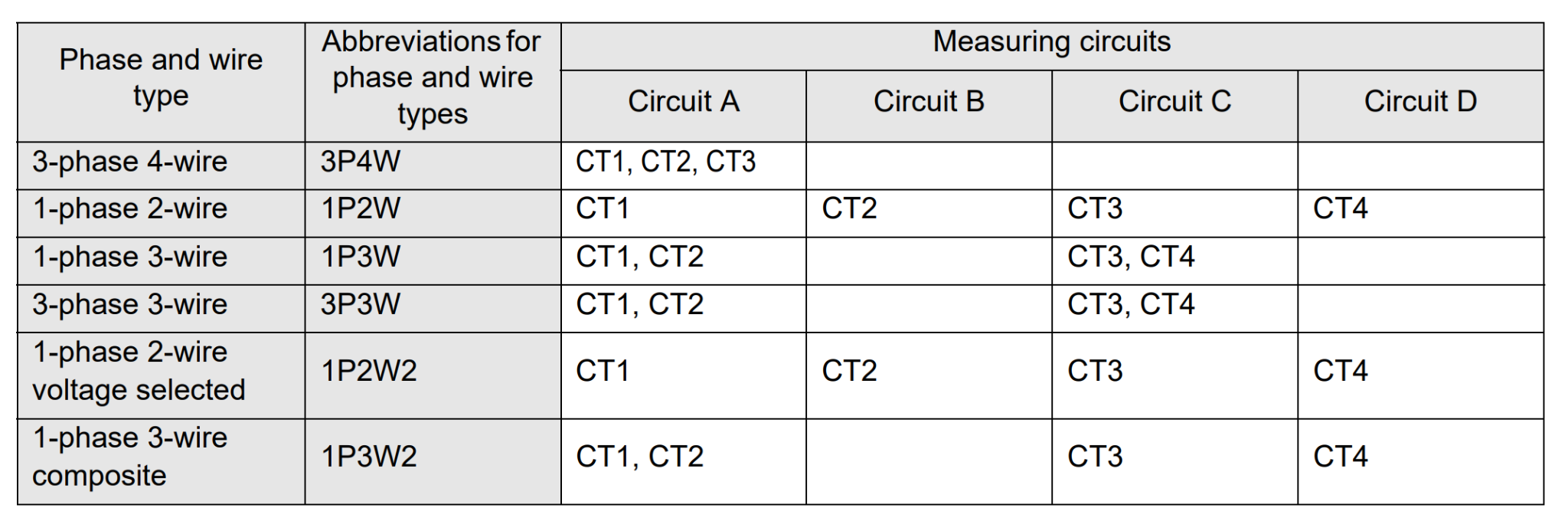
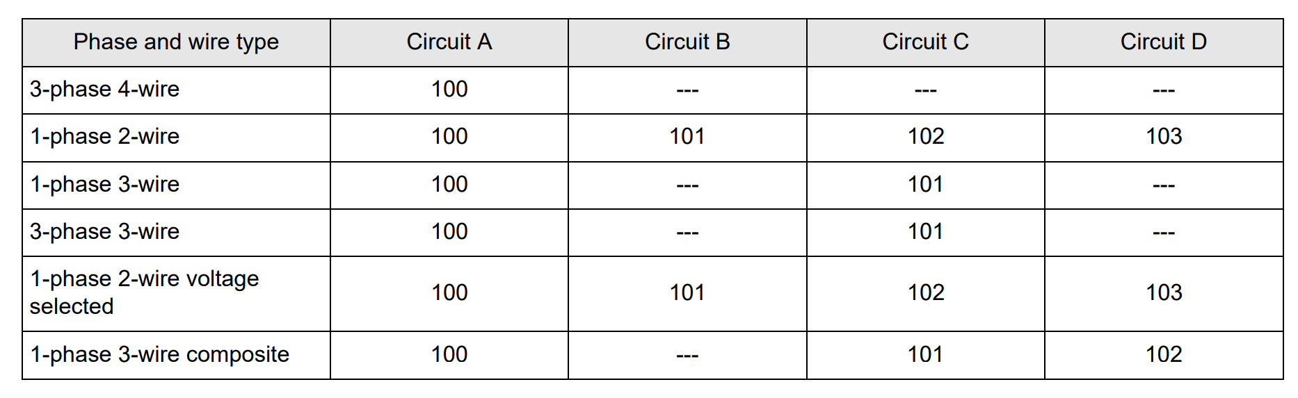
CT
The table below shows the phase/wire type and CT assignment for each measurement circuit. By enabling circuits B through D to increase the number of measurement points, power measurement is possible with the required number of circuits.
Note that it is disabled by default.
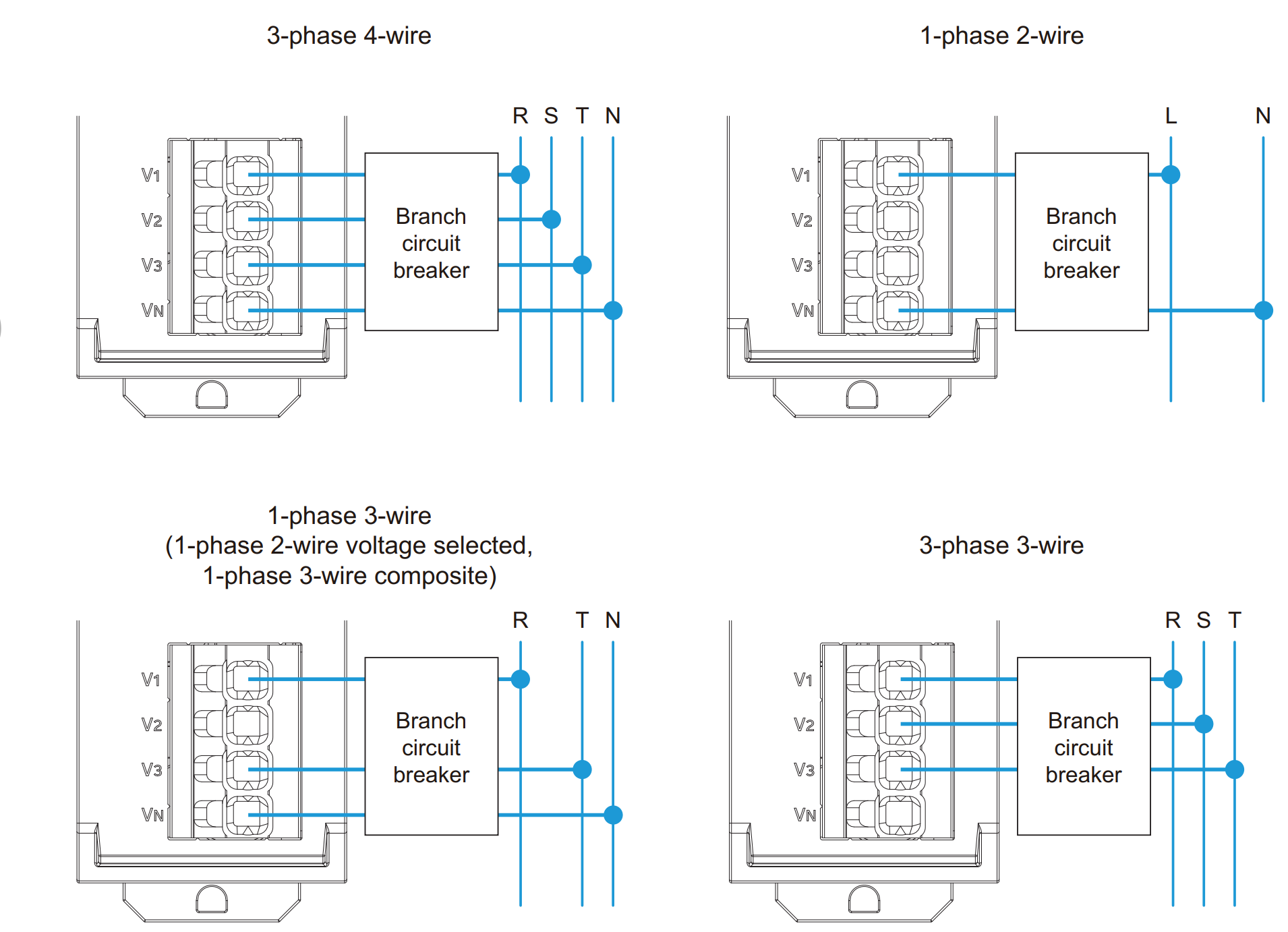
Power supply and monitored voltage input wiring
As shown in the diagram below, wire the equipment according to the phase and wire type.
Install branch circuit breakers between each of the R/S/T/N, L/N, and R/N/T wiring pairs to enable immediate power disconnection.
Ethernet/IP Connection Specifications
This is the Ethernet/IP connection specification for Omron’s KM-PMBN-EIP.

Assembly Object
This is the specification for each assembly of Omron’s KM-PMBN-EIP.
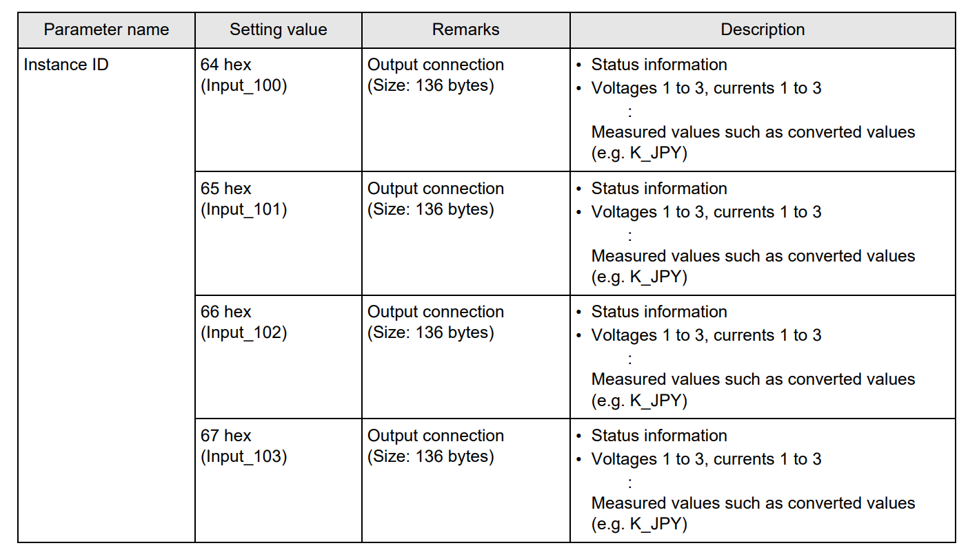
The correspondence between phase, wire type, and instance ID is as follows.
Instance ID 100-103
The assignments for instance IDs 100, 101, 102, and 103 are identical.
Status information
This is the meaning of the Status word in DWORD0.

Implementation
Now let’s actually create a project.
OMRON Side
First, configure from the Omron KM-PMBN-EIP side.

Download the tool
To configure the IP address and internal settings for the KM-PMBN-EIP, please download the Condition Monitoring Configuration Tool from the link below.
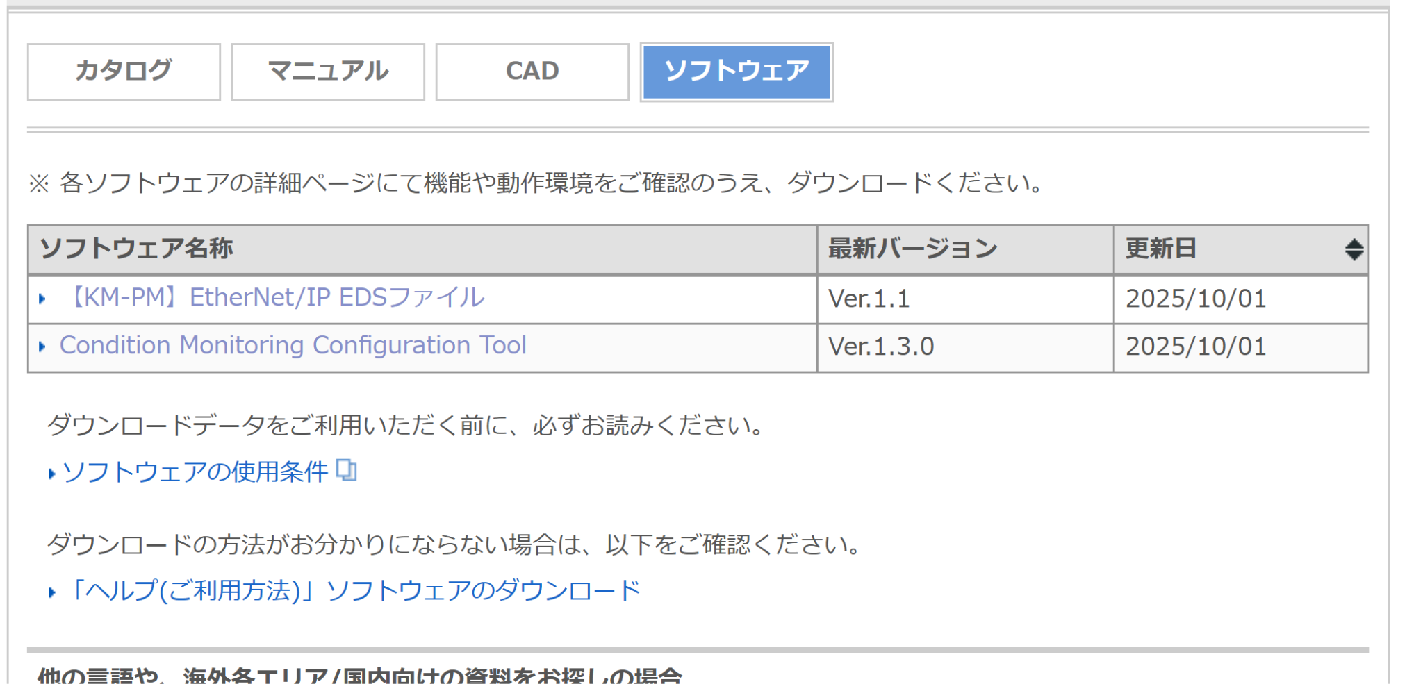
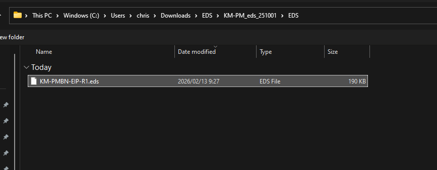
Download the EDS
Similarly, please download the KM-PMBN-EIP EDS file from the link below.
https://www.fa.omron.co.jp/products/family/3955/download/software.html

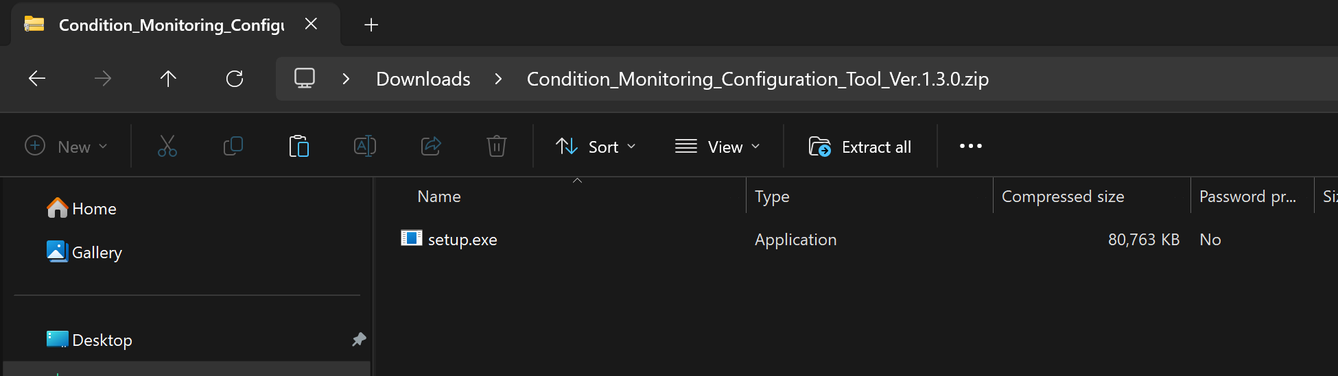
Tool Installation
Launch the setup file you downloaded earlier.
Set the installation language.
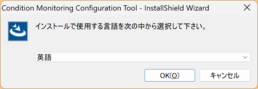
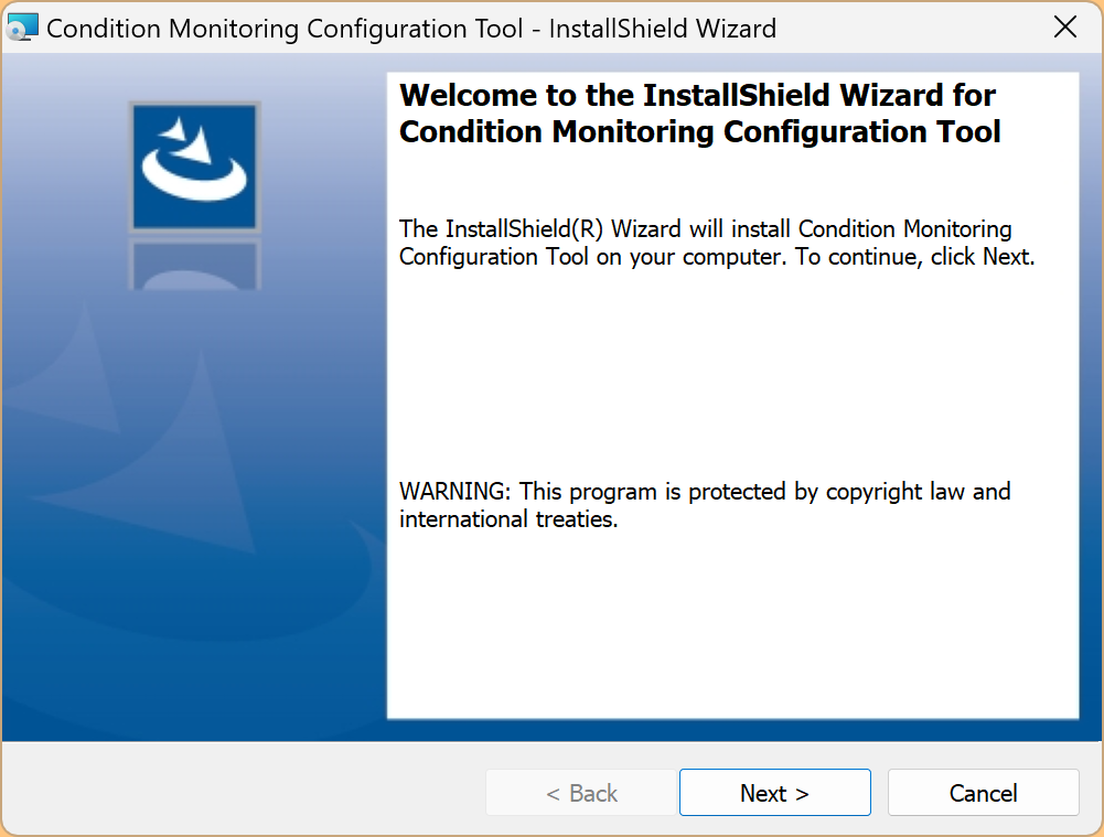
Next> to proceed.
Agree to the license and proceed with Next>.
Set the installation location for the tool, then proceed by clicking Next>.

Install the tool and start it.
Please wait a moment…
Done!
Create a project
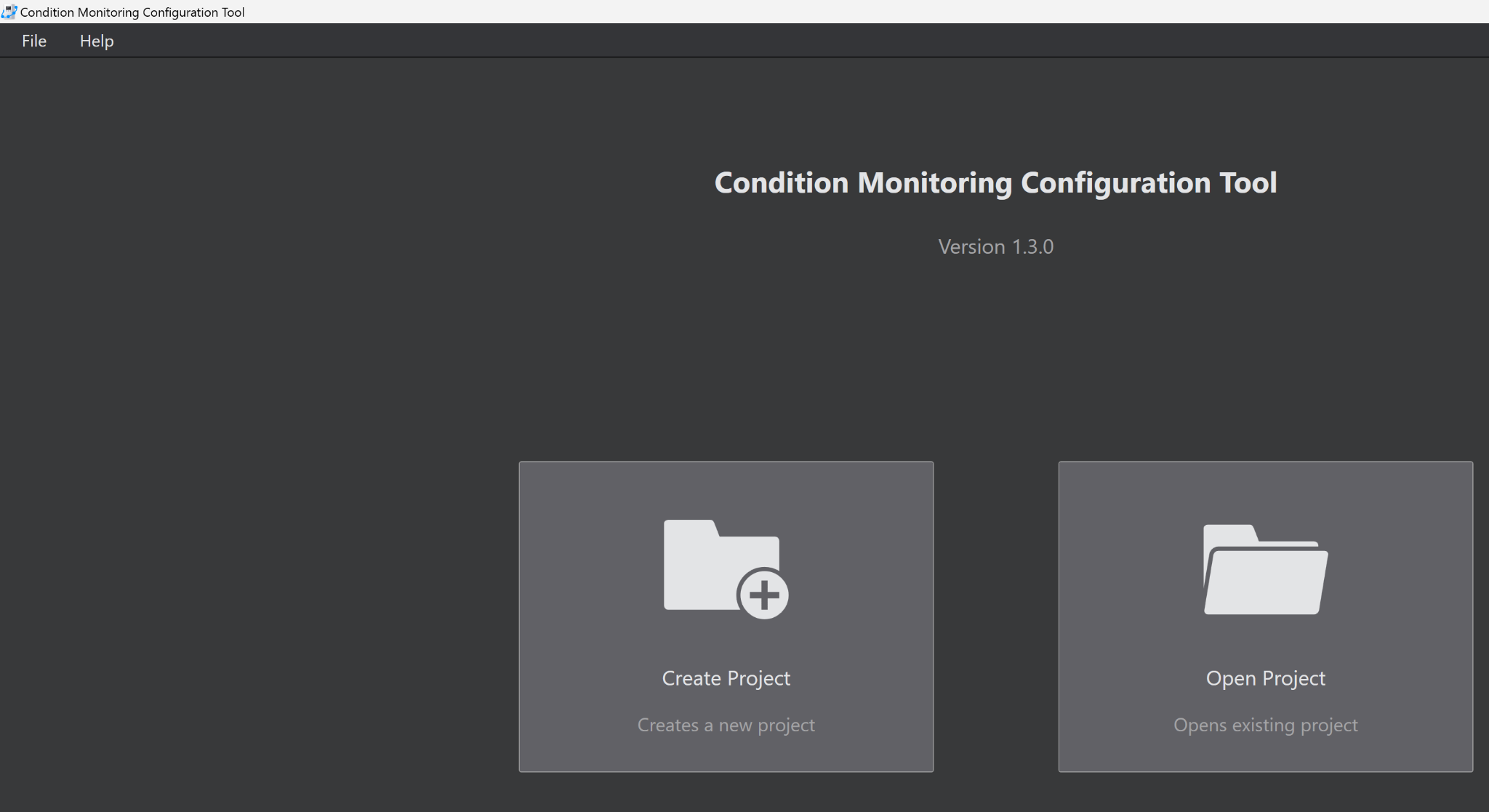
Launch the Condition Monitoring Configuration Tool from earlier and click Create Project.
Set the project save location and proceed by clicking OK.

Proceed with OK.
Add Device
Next, click the button shown below to add a new power meter.

Set the name of the power meter.
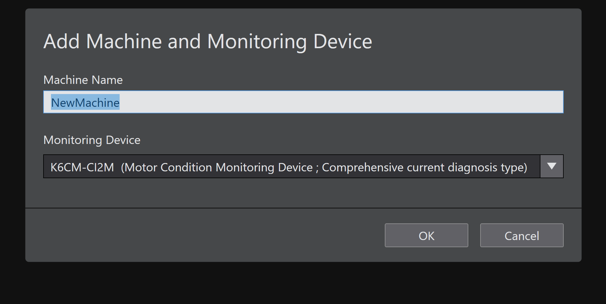
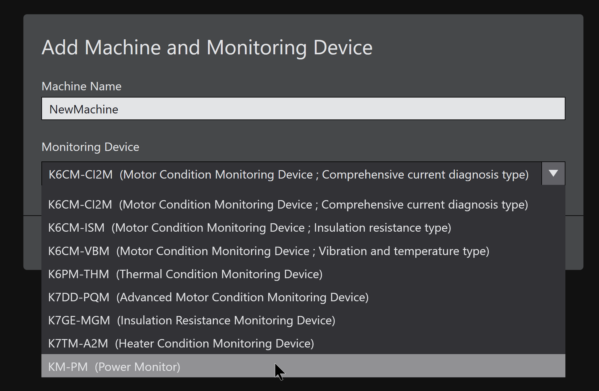
Select KM-PMBN-EIP from the drop-down list for use in this article.
Proceed with OK.

Done!

Main Unit Settings
Click the device you just added.

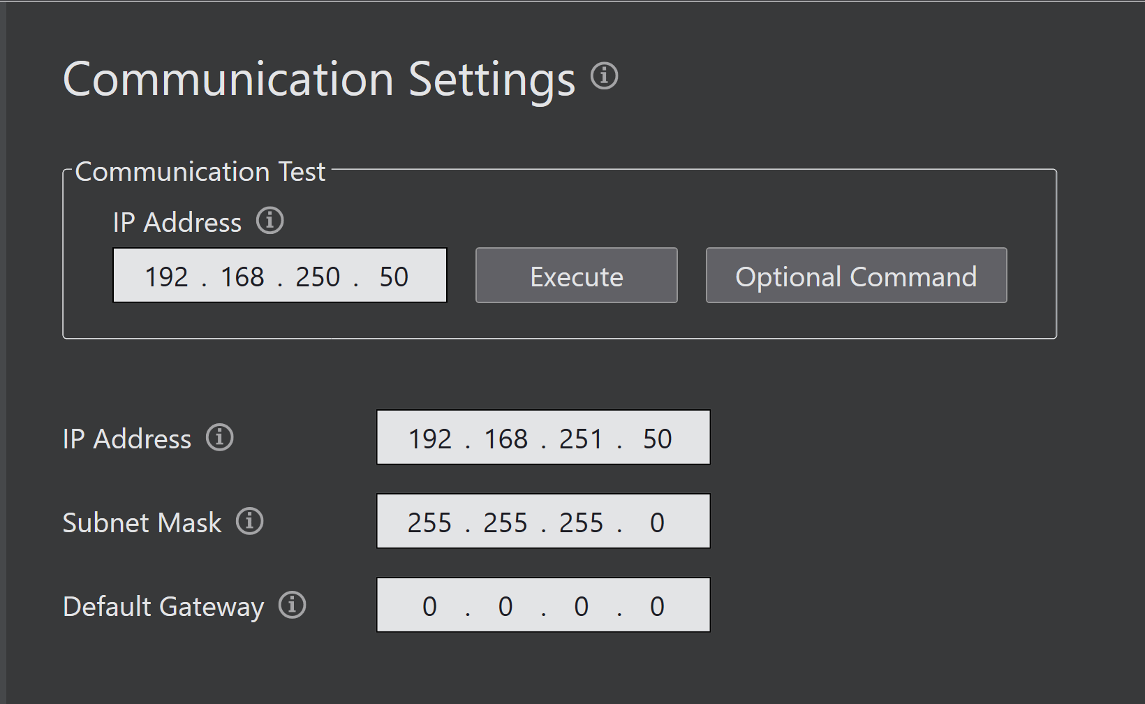
IP Setting
The factory default IP address is “192.168.250.50”. When configuring it on your PC, ensure it does not conflict with other devices. Also, set the IP address according to your application and write the IP address using the Write function.
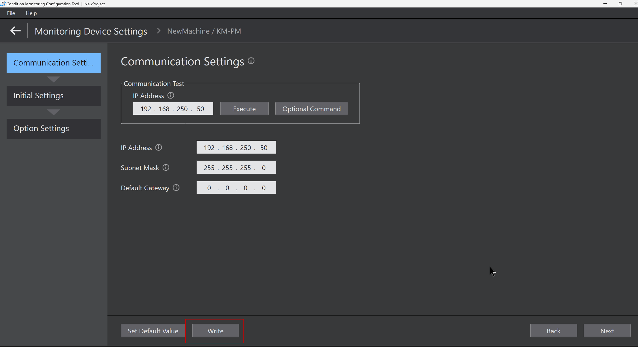
Just a second…

Done!

Additionally, you can click the Execute button to perform a communication test.
Initial Settings
Next, proceed to the Initial Settings Tab.

In this example, since it’s a 1P2W configuration, we’ll use CT1-4. Then set the conversion range for each CT → and write the parameters to the main unit using Write.

Codesys Side
Next, configure the Codesys side.

Import the EDS File
Click Tools→Device Repository.

Click Install.

Let’s install the EDS file you downloaded earlier.
Done!

Add the Ethernet Interface
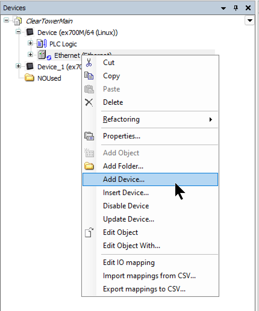
Right-click Device → Add Device.

Click Ethernet Adapter→Ethernet to add an Ethernet interface.

Add the Ethernet/IP Scanner
Next, right-click the Ethernet interface and select Add Device.
Select the Ethernet/IP Scanner → Add Device.

Add the Device
Finally, to add the Omron KM-PMBN-EIP used in this article, go to Ethernet/IP Scanner → right-click → Add Device.

Select Omron’s KM-PMBN-EIP → Add Device.

Done!The Omron KM-PMBN-EIP has been added to this.

IP Address
Configure the IP address of the Omron KM-PMBN-EIP according to your network configuration.

Add the Connection
Next, add an Ethernet/IP connection.
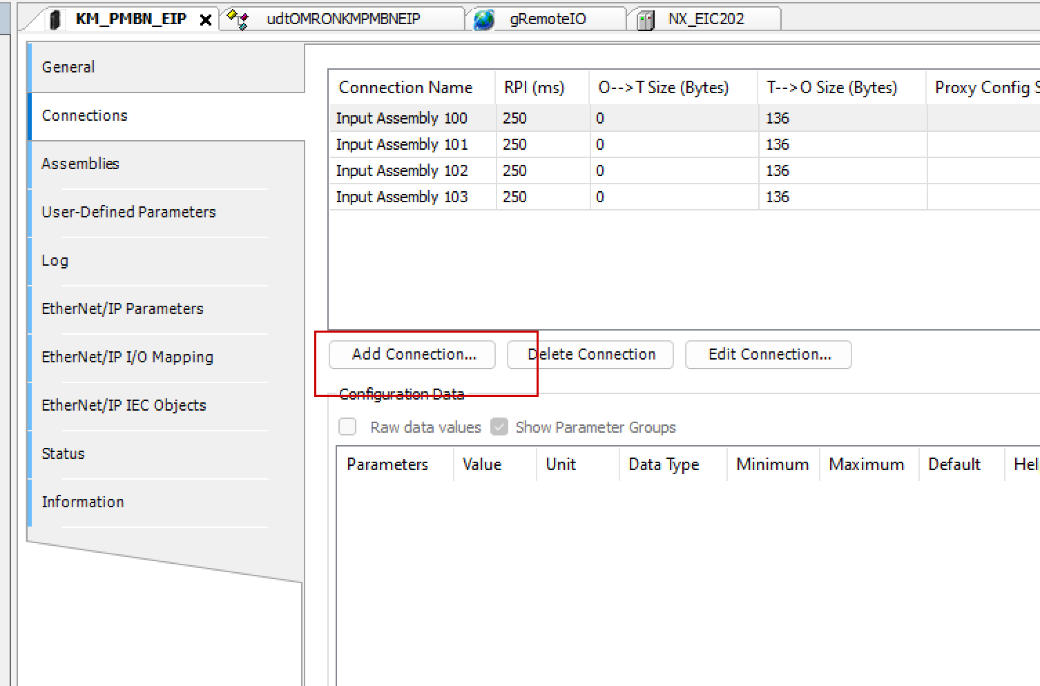
In this example, since it’s a 1P2W configuration, we will use CT1-4, so please add it to Assembly 100-103 as well.

Done!
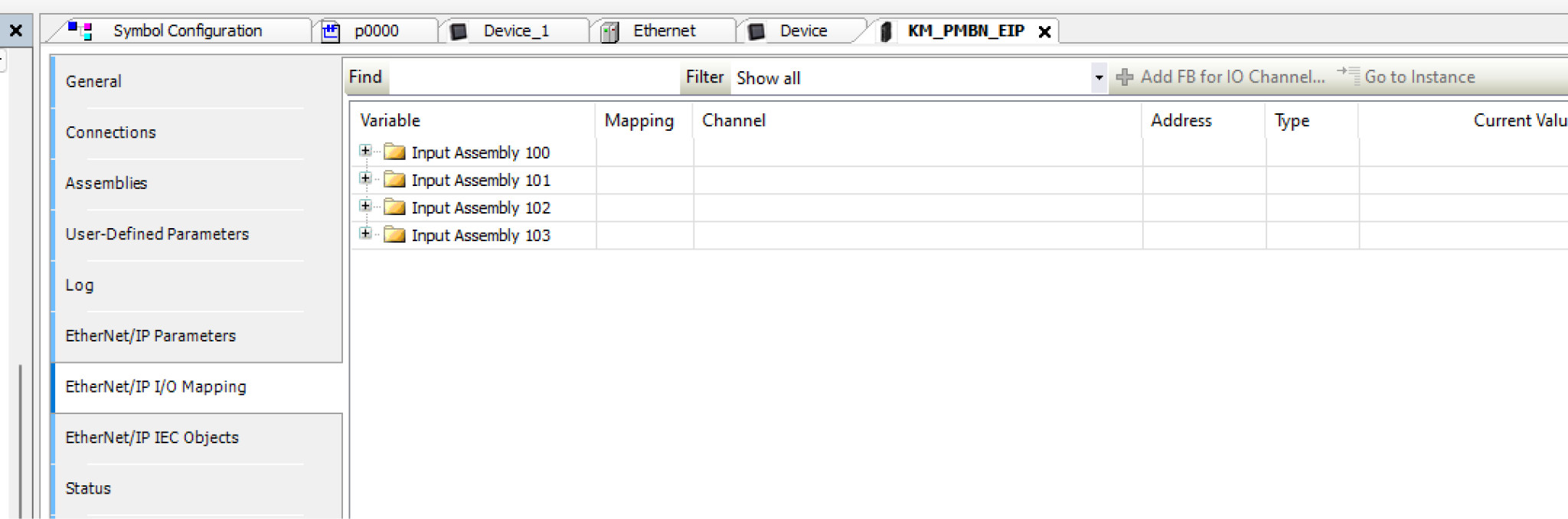
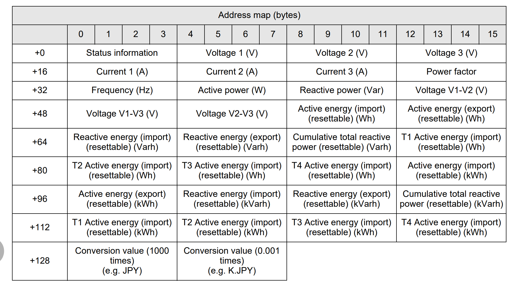
Address mapping
Finally, it’s the address configuration. Since the Omron KM-PMBN-EIP is divided into sections for each connection, forcing an address at the beginning makes GVL mapping easier.

DUT
This is a structure created to match the Ethernet/IP connection for Omron’s KM-PMBN-EIP.
TYPE udtOMRONKMPMBNEIP :
|
|---|
GVL
Next, create a GVL and define variables using the structure created earlier. Also, use the AT keyword to map to the specified address.
{attribute ‘qualified_only’}
|
|---|
Download
Finally, download the project to the Codesys Runtime and run the Runtime.
Result
Done!Codesys Runtime and Omron’s KM-PMBN-EIP have established an Ethernet/IP connection.

We were able to check the voltage for each instance.
