This article explains how to receive and control the STO signal of an OMRON R88D FSoE servo using FSoE communication via EtherCAT in a Beckhoff TwinCAT + EK1960 (TwinSAFE) configuration. It covers configuring safety function blocks (FBEstop / FBDecouple etc.) in the TwinSAFE Editor, maintaining state using TwinCAT ST structures, implementing STO signal trigger processing in the MAIN program, and includes an example of HMI screen integration.
Alright, let’s enjoy the FA.
Foreword
Thank you from the bottom of my heart for visiting my technical blog and YouTube channel.
We are currently running the “Takahashi Chris” radio show with Full-san (full@桜 八重 (@fulhause) / X) which I deliver every Wednesday night.
Sharing, not hoarding, technical knowledge
We publish technical information related to factory production technology and control systems for free, through blogs and videos.
With the belief that “knowledge should be accessible to everyone,” we share practical know-how and real-world troubleshooting cases from our own field experience.
The reason we keep it all free is simple: to help reduce the number of people who struggle because they simply didn’t know.
If you’ve ever thought:
- “Will this PLC and device combination actually work?”
- “I’m having trouble with EtherCAT communication—can someone test it?”
- “I want to try this remote I/O, but we don’t have the testing environment in-house…”
Feel free to reach out!If lending equipment or sharing your configuration is possible, we’re happy to verify it and share the results through articles and videos.
(We can keep company/product names anonymous if requested.)
How can you support us?
Currently, our activities are nearly all unpaid, but creating articles and videos takes time and a proper testing environment.If you’d like to support us in continuing and expanding this content, your kind help would mean a lot.
Membership (Support our radio show)
This support plan is designed to enhance radio with Mr Full.
https://note.com/fulhause/membership/join
Amazon Gift List (equipment & books for content production)
Lists equipment and books required for content creation.
https://www.amazon.co.jp/hz/wishlist/ls/H7W3RRD7C5QG?ref_=wl_share
Patreon (Support articles & video creation)
Your small monthly support will help to improve the environment for writing and verifying articles.
https://www.patreon.com/user?u=84249391
Paypal
A little help goes a long way.
https://paypal.me/soup01threes?country.x=JP&locale.x=ja_JP
Just trying to share things that could’ve helped someone—if only they’d known.
Your support helps make knowledge sharing more open and sustainable.
Thank you for being with us.
soup01threes*gmail.com
Technical knowledge shouldn’t be kept to ourselves.
Reference Link
http://soup01.com/en/?s=EK1960+
OMRON R88 Series FSOE Connection
The bottom of the OMRON R88D-1SN series servo drive features an “FS” (FSoE Status) indicator, allowing you to check the FSoE communication status and errors at a glance.
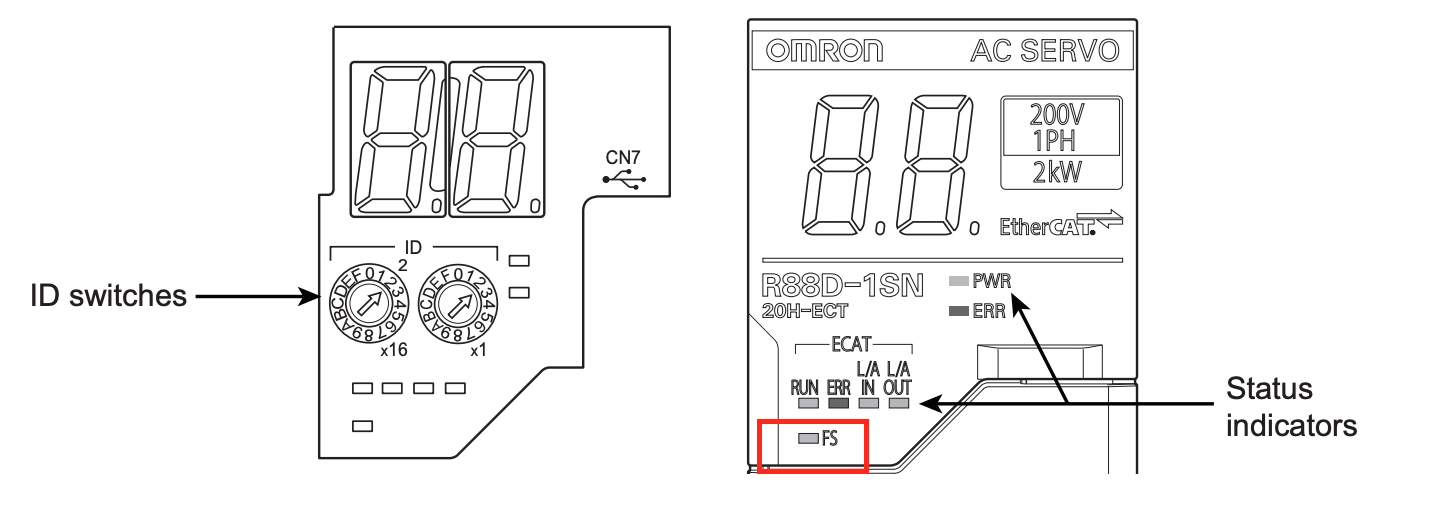
Display | Status | Description |
|---|---|---|
Green ON | FSoE slave communication established | TwinSAFE and other safety CPUs have completed FSoE communication. STO is in a usable state. |
Flashing Green | FSoE slave communication establishing | Communication establishment processing in progress. Confirming connection destination master and FSoE address. |
Flashing Red | Critical error | One of the following errors: safety parameter error, communication timeout, self-diagnostic error, etc. → STO via FSoE is disabled. |
What is the Safe Torque OFF (STO) function?
STO (Safe Torque OFF) is a function that safely stops torque output by interrupting the motor’s current supply. This function is executed by a signal from the safety controller, causing the servo to transition to a “safe state.”
When STO becomes active, the servo turns OFF the “READY” output and enters a safe state.
STO Control Method for the 1S Series (OMRON)
The 1S Series servo (EtherCAT-integrated model) supports the following two STO methods:
- STO via Safety Input Signals Hard contact control (highly reliable, constant)
- Safety Communication via EtherCAT (Slimmer, More Flexible Wiring)
Depending on the safety equipment configuration used, decide which method to choose.
STO Method | PFH Value ([1/h]) | Safety Level |
|---|---|---|
Safety input method | 2.0 × 10⁻¹¹ | Extremely high reliability |
FSoE communication method | 1.6 × 10⁻⁹ | High reliability |
PFH(Probability of dangerous Failure per Hour)
PFH is the probability of a “dangerous failure” occurring per hour. In other words, it is a numerical value that evaluates, on a “per hour” basis, the probability that a safety device or safety function will not operate as expected and create a hazardous condition. For example:
If PFH = 1 × 10⁻⁹ [1/h], this means that statistically, one dangerous failure will occur every 1 billion hours (approximately 110,000 years).
Safety Design and Operational Precautions
Important Notes During Setup
Before performing download or restore operations, confirm that the equipment is not operating. To prevent accidents caused by unintended operation, ensure physical safety measures are in place.
Additionally, after completing the configuration, be sure to conduct user testing and verify that all safety devices are functioning correctly.
Precautions When Replacing Equipment
The servo drive before replacement must be in factory default condition. If the servo’s status is unclear, perform parameter initialization. Also, reconfirm that the replacement unit’s model number, terminal block arrangement, and mounting position are correct.
Precautions During Trial Operation
When conducting trial operation using Sysmac Studio or similar software, if the EtherCAT cable is not connected, the STO function via FSoE will be temporarily disabled!
If you want to use the STO function even during such trial operation, use STO control via safety input signals (hardware contacts).
What is STO?
STO (Safe Torque Off) is a safety function that cuts off the power supply to the servo motor to prevent torque generation. By using TwinCAT and Beckhoff’s EK1960 (TwinSAFE), this
STO can be remotely triggered via FSoE (Safety over EtherCAT) in accordance with safety standards.However, STO is a means of “emergency stop” or “torque cutoff,” and does not guarantee that “the motor will come to a complete stop” or that it will be “held safely.”
Precautions:
Here are the precautions when using STO:
Safety risk assessment is mandatory
Before implementing STO, always conduct a risk assessment of the entire machine/system. Be aware that there are cases where STO alone is not sufficient for safety.
Motor may not come to a complete stop
For vertical axes or directions where gravity applies, there is a risk of workpieces falling, so adding an external brake may be necessary.
Pay attention to free-stop distance
With “free stop + dynamic brake disabled” settings, there is a possibility of long-distance coasting.
Possibility of micro-rotation during internal device failure
In the unlikely event that power transistors or other components are damaged, rotation of up to 180 electrical degrees may occur. STO turns off the power to the motor, but the drive itself remains energized. Also, since power continues to be supplied to the servo drive unit itself, be sure to turn off the main power separately during maintenance.
EDM output is not a “safety output”
EDM (External Device Monitoring) is an auxiliary signal for self-diagnosis confirmation and should not be used as a safety output.
Wiring Checklist
Wiring mistakes can cause safety function malfunctions, so be sure to check the following:
- Short circuits or disconnections
- EDM output polarity
- Whether SF1/SF2/EDM are operating correctly
Operation confirmation every 3 months when using STO with safety inputs
Safety functions should be checked regularly. Even with FSoE communication, it is necessary to check whether self-diagnosis errors occur when powering ON/OFF.
Do not allow programs to automatically reset STO
Design the PLC program so that STO is not automatically disabled even when emergency stop is released or EDM abnormalities occur.
Pay special attention to vertical axes
There is a possibility of accidents where the workpiece falls because the brake does not engage in time after the servo turns off, so pay attention to the timing of brake ON and the sequence of power OFF.
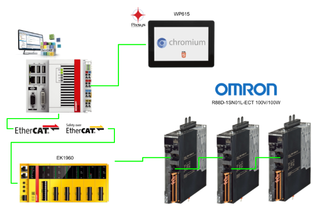
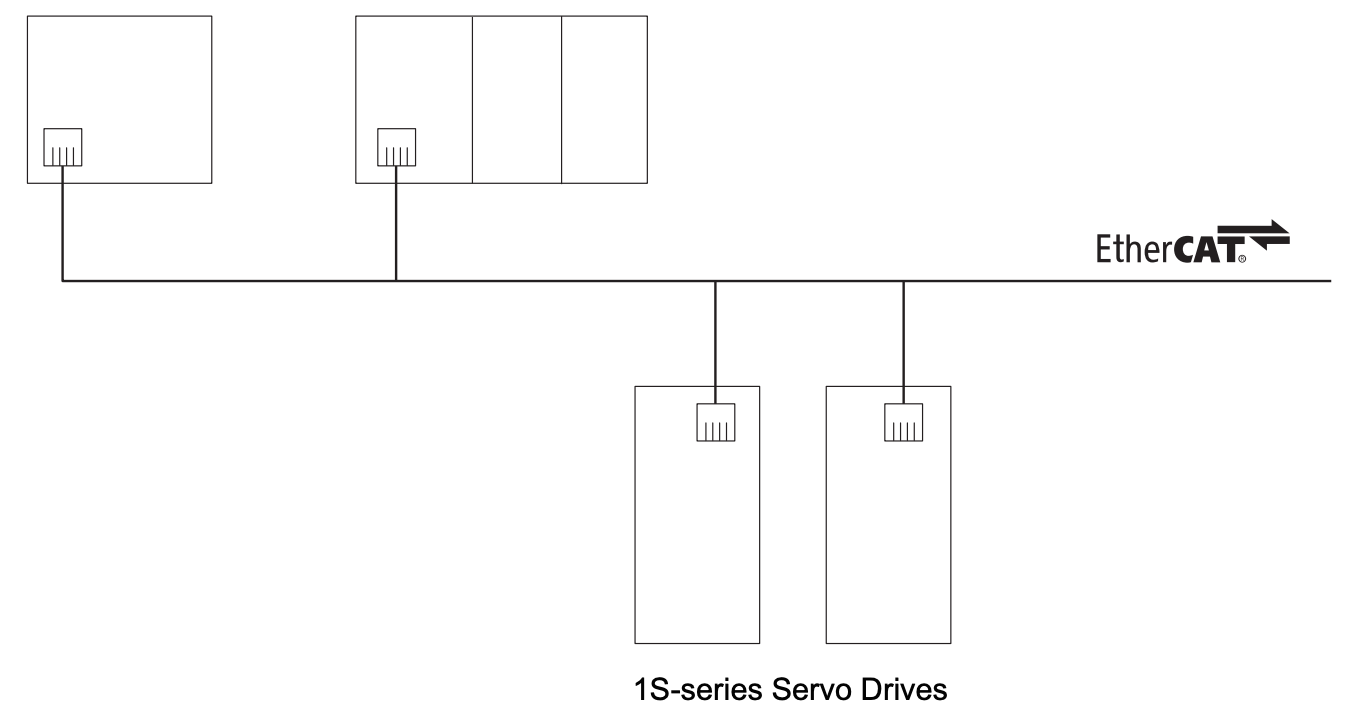
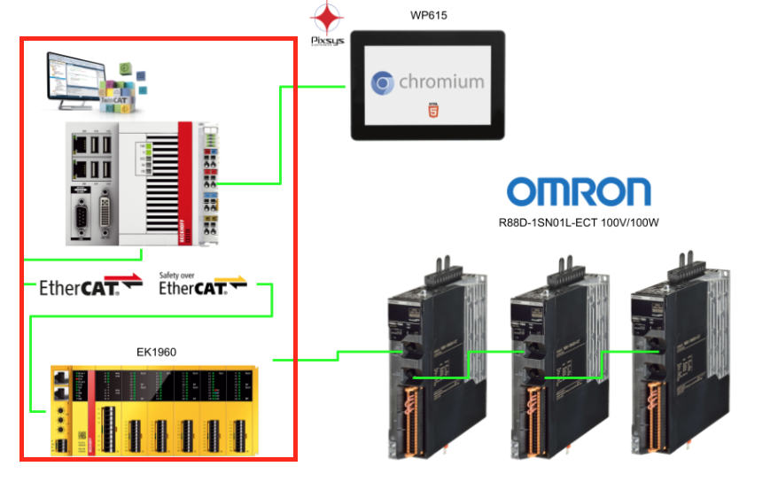
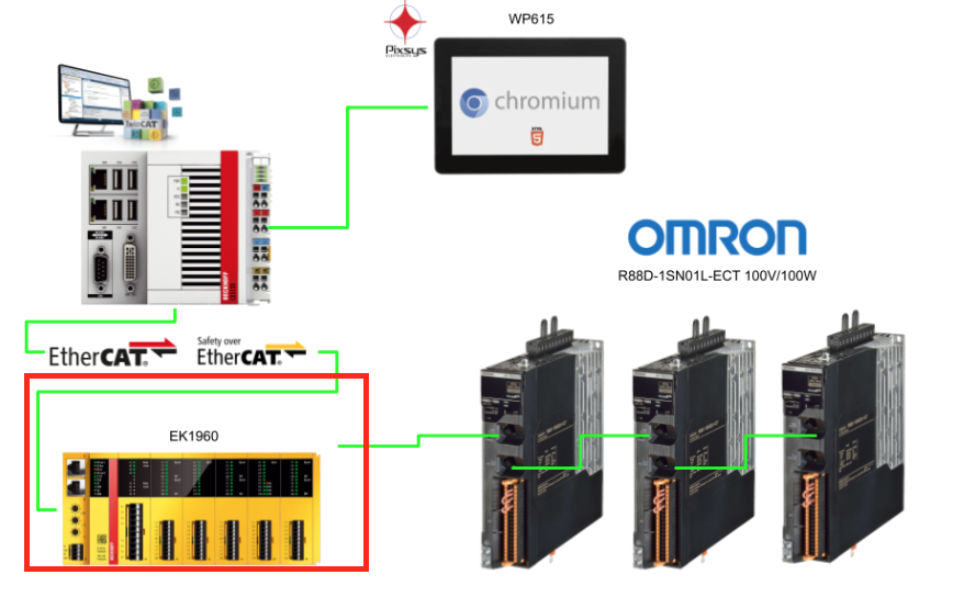
Connection Example for Using STO Function with FSoE
This configuration is a basic network diagram for controlling the STO function of OMRON 1S series servo drives via FSoE (Safety over EtherCAT).
Device Name | Role |
|---|---|
EtherCAT Master | IPC running TwinCAT3, etc. Performs overall control |
Safety CPU Unit | In this case, Beckhoff EK1960, etc. Processes FSoE safety logic |
Safety I/O Unit | Includes TwinSAFE EL1904 (input) and EL2904 (output), etc. |
OMRON 1S Series Servo Drive | Servo capable of turning STO function ON/OFF via FSoE signals over EtherCAT |
PDO Configuration and FSoE Communication Setup with Safety CPU
Step ①: Adding Safety PDO
In the EtherCAT network configuration, add Safety PDO (for FSoE) to the 1S series servo drive.
- RxPDO (Receive PDO): 273th → 0x1710
- TxPDO (Transmit PDO): 273th → 0x1B10
This is the communication channel necessary for the servo to act as an FSoE slave, and it contains the area for safety signals to remotely control the STO function.
Step ②: Enable 1S Servo in Safety CPU Unit Configuration
On the TwinCAT Safety Configuration (TwinSAFE Editor) side, enable the 1S servo as an FSoE slave device and set the appropriate FSoE address.
Step ③: Creating Safety Logic
In the TwinSAFE Project, configure the logic as follows: For example, EL1904 → receives input from emergency stop switches, etc., EL2904 → sends signals to the servo through STO output. Alternatively, use the built-in logic IO of the EK1960 used in this article.
At this time, what is output as the STO signal is of “SafeBool” type and is mapped to the STO input of the 1S servo.
Step ④: Establishing Connection Between EtherCAT Communication and Safety CPU
Establish communication between the EtherCAT master (IPC) and the Safety CPU Unit (such as EK1960). If communication is not established after configuration changes, clear the FSoE slave address once and reconfigure it.
PDO Configuration Used in FSoE Communication
To perform STO control via FSoE (Safety over EtherCAT) for the OMRON 1S series servo drive, the following PDO configuration must be correctly set up and coordinated with the control program.
RxPDO (0x1710): Master → Servo (for control)
Name | Description |
|---|---|
STO Command | STO function execution command. 0: STO active (torque cutoff) 1: STO reset (re-enable operation) |
Error Acknowledge Reset | Safety function error reset signal. Reset is executed on the rising edge of 0→1. |
TxPDO (0x1B10): Servo → Master (for status monitoring)
Name | Description |
|---|---|
STO Status | Indicates STO status. 0: Normal (STO inactive) 1: STO active (torque cutoff) |
Error Acknowledge | Safety function error status. 0: Normal 1: Detects abnormality in STO internal circuit |
Safety Connection Status | Flag indicating safety connection progress status. Used on the safety program side for Activate input and connection status confirmation |
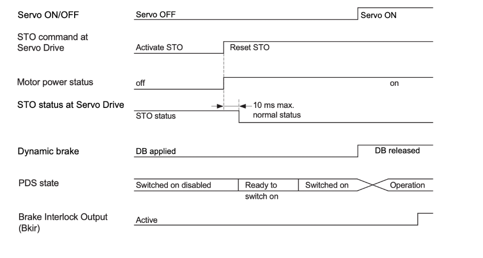
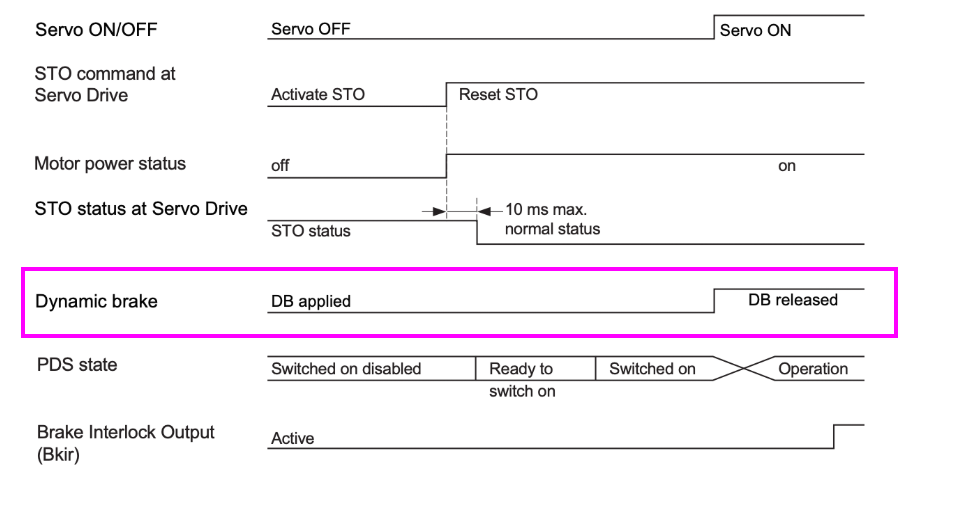
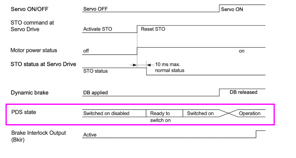
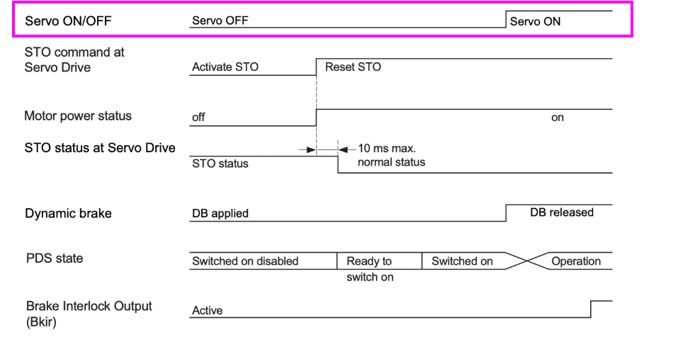
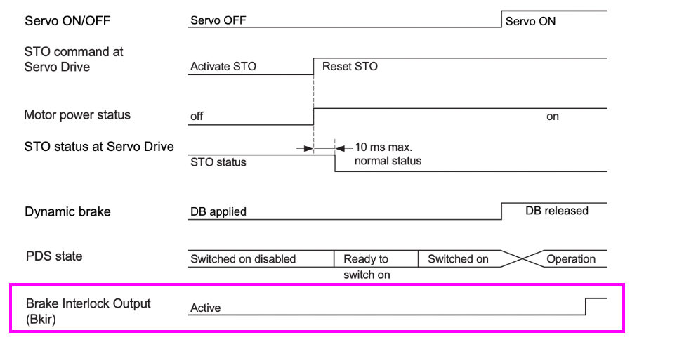
Time-Series Timing Chart During STO (Safe Torque Off) Operation
This diagram shows the series of signal changes and response times when STO is activated from the Safety CPU.
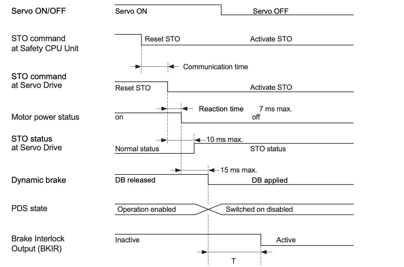
Servo ON/OFF
Turn the servo OFF using STO from the ON state.
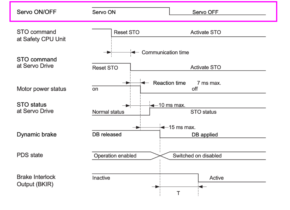
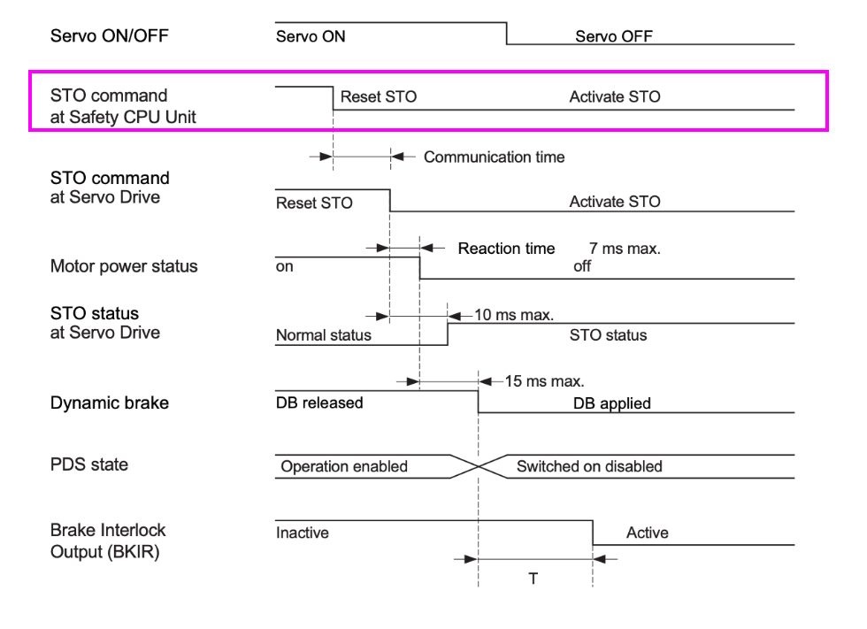
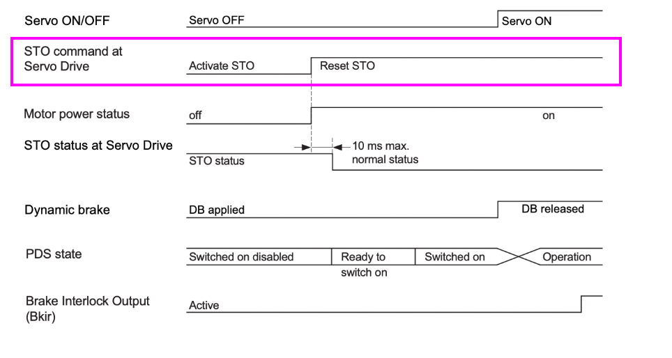
STO Command at Safety CPU Unit
Switch the STO command from the safety PLC (such as EK1960) from Reset STO to Activate STO.
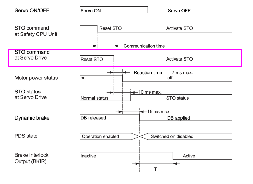
STO command at Servo Drive
Next, the servo drive will enter the STO command state, including communication delay.
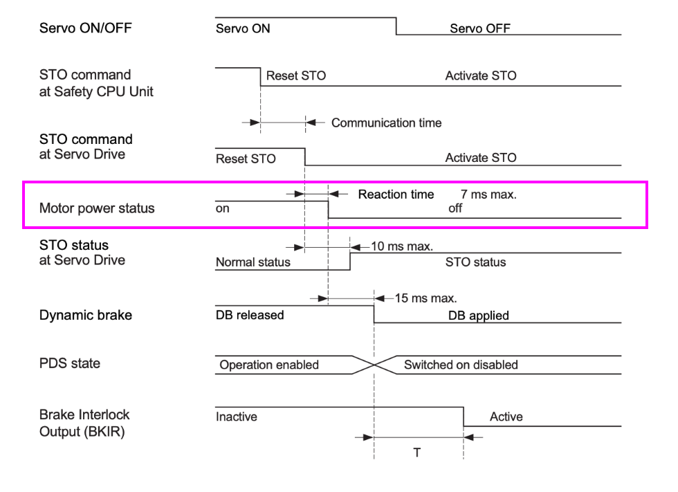
Motor power Status
Switch the motor power supply from ON to OFF within 7 milliseconds.
STO status at Servo Drive
The servo will transition to STO state within 10 milliseconds.
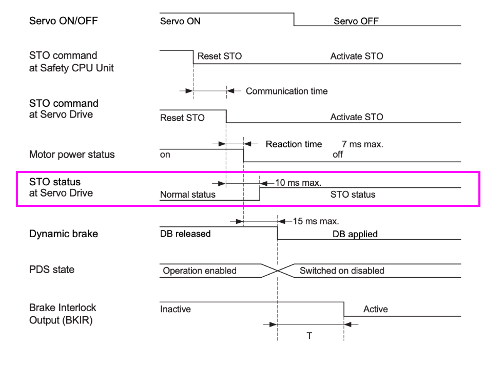
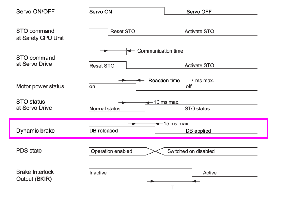
Dynamic Brake
Dynamic braking transitions from DB Released to DB Applied within 15 milliseconds.
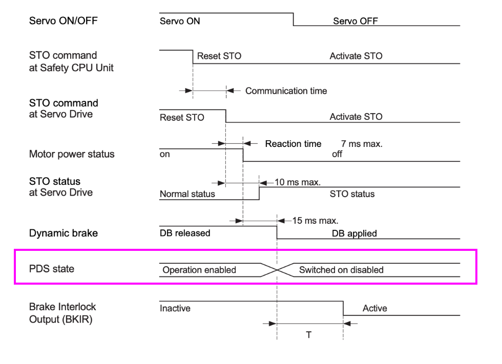
DS State
The Power Drive System state transitions from Operation enabled → Switched on disabled
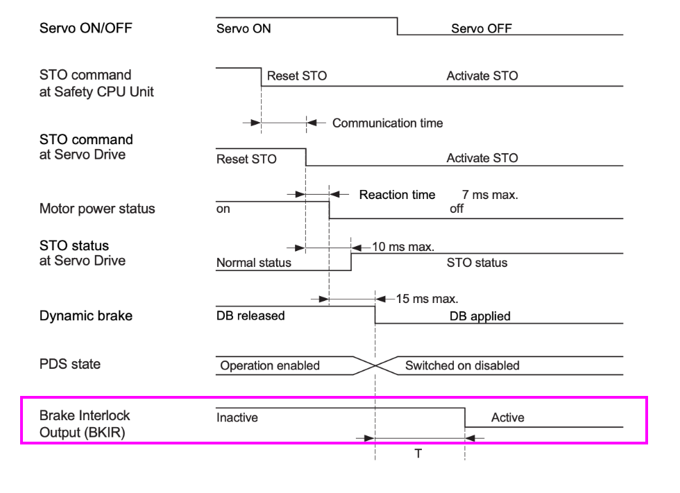
BKIR(Brake Interlock Output)
The brake interlock output transitions from Inactive to Active after time T.
The delay “T” for the brake signal (BKIR) until it becomes active is determined by one of the following conditions:
Parameter | Description |
|---|---|
4610-82 hex | Timeout at Servo OFF (time-based) |
4610-83 hex | Threshold Speed at Servo OFF (speed-based) |
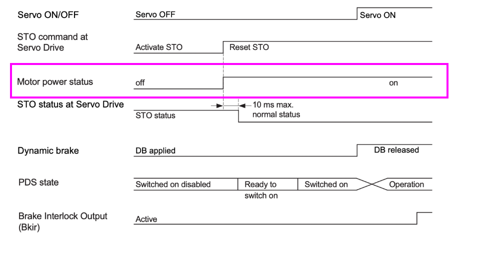
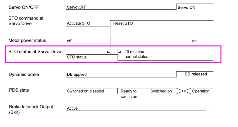
Time-Series Timing Chart During Recovery Operation from Safe State
This diagram shows the series of signal changes and response times when recovering from Safe State.
Also, even when the emergency stop switch is released, explicitly manage the STO release conditions on the safety controller side so that STO is not automatically reset.
STO Command(at Servo)
A Reset STO command will be issued.
Motor Power Status
Power is restored, and the motor transitions from off to on.
STO Status(at Servo)
The Servo Drive transitions from STO state to normal state within 10 ms.
Dynamic Brake
Next, the DB is released, allowing the motor to rotate.
PDS State
Next, the PDS transitions in stages: Switched on disabled → Ready to switch on → Switched on → Operation.
Servo ON/OFF
When the PDS State transitions to Operation, the servo transitions to the ON state.
BKIR
The brake interlock returns from ON to OFF (released).
Implementation
TwinCAT Side
We’ll start with the TwinCAT side first.
Configure OMRON Slot
When using the OMRON R88D-1SN series servo with TwinCAT, to perform STO control via FSoE communication, it is necessary to add an FSoE slot in the “Slot” configuration screen.
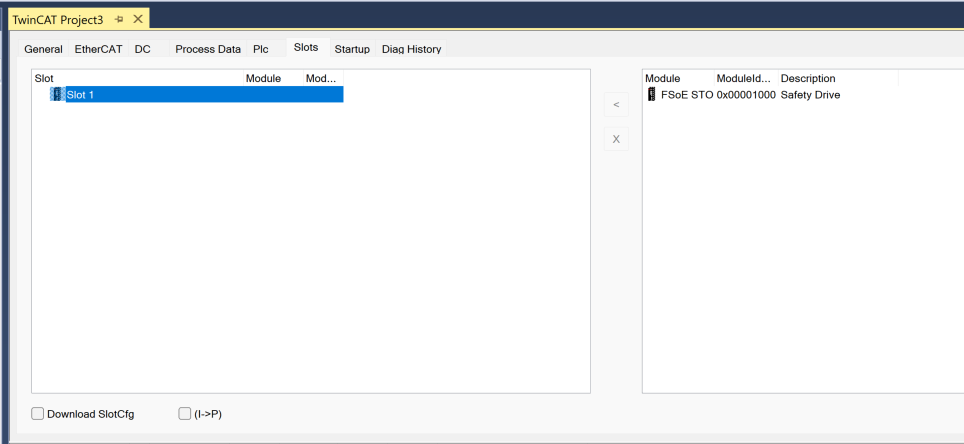
To configure the OMRON FSoE-STO slot in TwinCAT, select FSoE STO 0x00001000 Safety Drive, click the “<” button in the center to add to Slot, and it will be registered as “Slot 1” in the slot list on the left side.
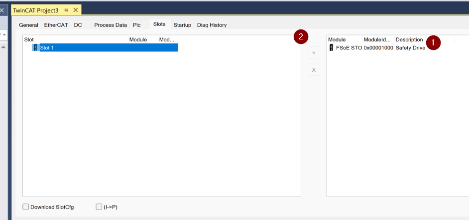
The FSoE STO module for the OMRON 1S servo has been added to the TwinCAT project.
EK1960 Side
Build the EK1960 side.
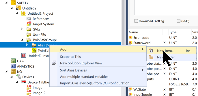
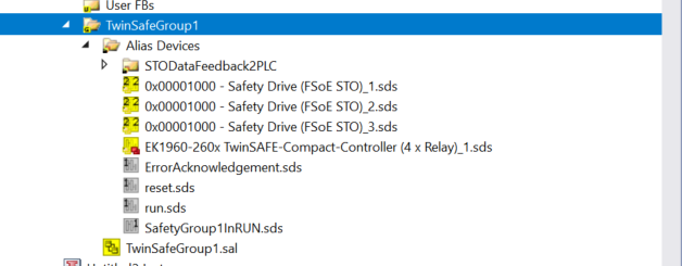
Add Alias Devices
To reference and control FSoE slave devices such as OMRON servos from within TwinSAFE logic, they must first be registered as Alias Devices. This can be done by right-clicking on “Alias Devices” in the TwinSAFE project and selecting “Add” → “New Item…”.
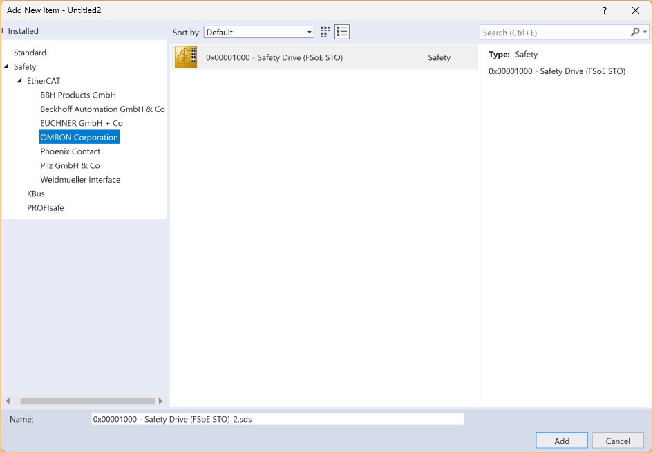
When creating a new Alias Device in a TwinSAFE project, selecting “Safety > EtherCAT > OMRON Corporation” displays the module “0x00001000 – Safety Drive (FSoE STO)” in the list. By selecting this and pressing the Add button, an Alias Device is created that allows the OMRON STO slave to be controlled within TwinSAFE.
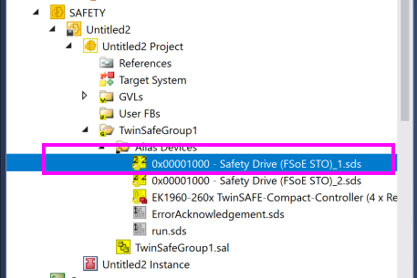
This screen confirms that the .sds file for 0x00001000 – Safety Drive (FSoE STO) has been properly added to “Alias Devices” within the TwinSAFE project.
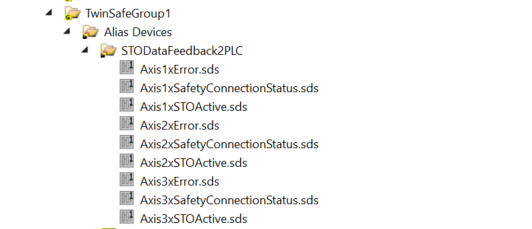
Add a device folder “STODataFeedback2PLC” for STO feedback used in communication with the PLC within TwinSafeGroup1 of the Safety project. This area is primarily used for monitoring the status of STO (Safe Torque Off) signals and transferring status to the PLC side (for indication purposes).
Within the TwinSafeGroup1 project, create “STODataFeedback2PLC” as a virtual alias folder to return the STO status and error information of each axis (Axis1~3) to the PLC.
Add the following three signals for each axis to this folder:
- AxisxError.sds: Error status related to SERVO (e.g., communication disconnection or abnormality)
- AxisxSafetyConnectionStatus.sds: Safety communication establishment status (FSoE connection status)
- AxisxSTOActive.sds: Status of whether STO is active
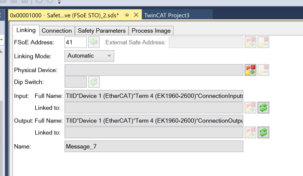
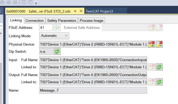
Next, open the Linking settings screen in the OMRON FSoE connection Object.
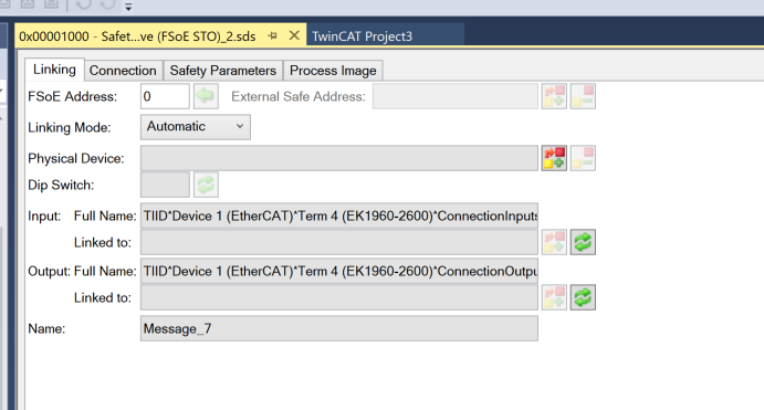
FSoE Address
The default FSoE address for each FSoE connection is 0.
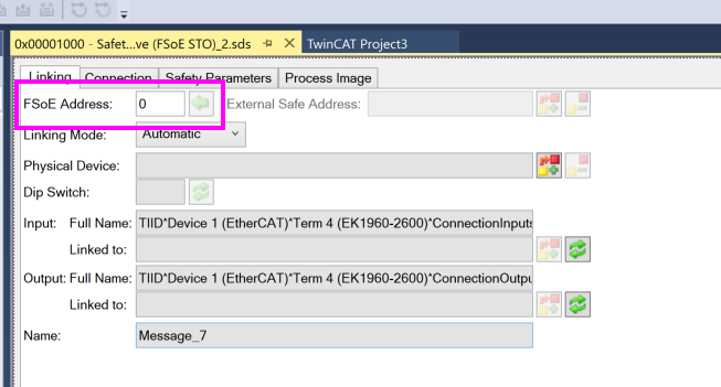
In this example, set the FSoE address to 41.
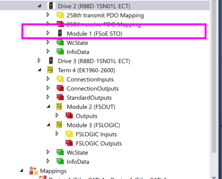
Physical Device
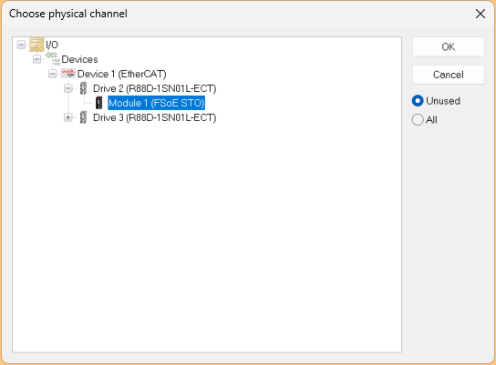
In TwinCAT, link the physical device (= actual EtherCAT slave) to the Safety Device (FSoE STO).
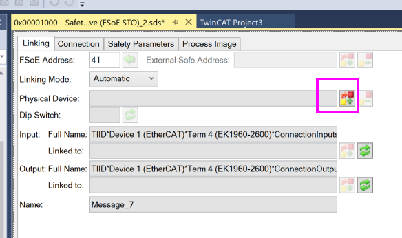
A window titled “Choose physical channel” appears, so expand the corresponding Drive in the EtherCAT configuration, select “Module 1 (FSoE STO)” within it, and press “OK”. This correctly associates the software STO configuration with the physical FSoE output module.
Done!
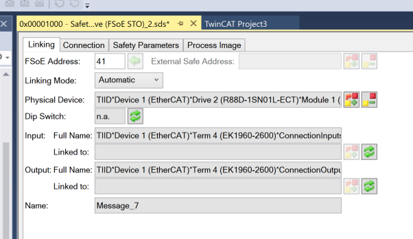
After saving the project, the Linked To field in Input/Output is automatically updated.
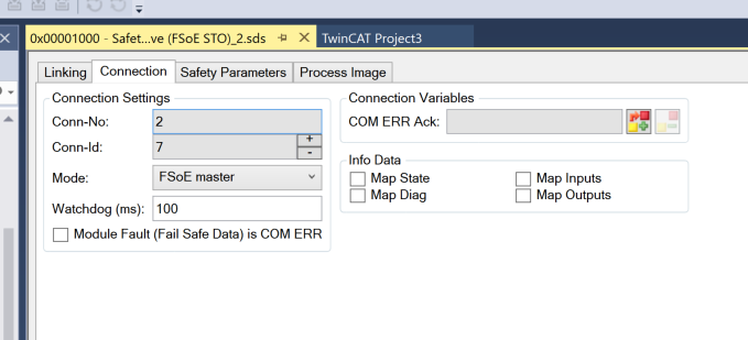
Connection Parameters
The Conn-Id in the Connection parameters is automatically set, so there’s no need to worry about it.
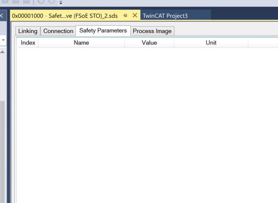
Safety Parameters
There are no particular settings to configure in the Safety Parameters Tab for the OMRON FSoE connection.
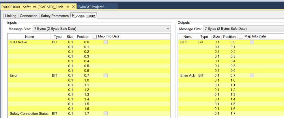
Process Image
In Process Image, you can view a list of safety inputs and outputs that exchange data via FSoE.
GVL
These are the TwinSAFE variables defined in this article.
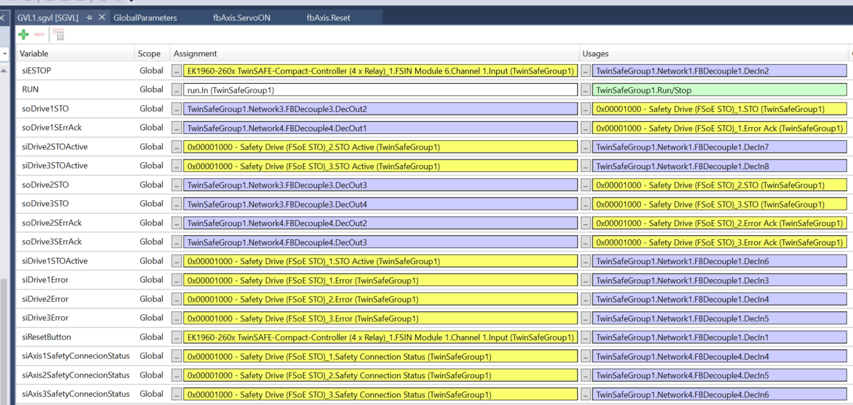
Variable Name | Purpose |
|---|---|
siESTOP | Emergency stop button input (acquired from EK1960 FSIN) |
RUN | Overall system RUN signal (TwinSafe RUN control) |
soDrive1STO | STO output signal to Drive1 |
soDrive1ErrAck | Error acknowledgment signal for Drive1 |
soDrive2STOActive | STO active signal for Drive2 (output) |
soDrive3STOActive | STO active signal for Drive3 (output) |
soDrive2STO | STO output signal to Drive2 |
soDrive3STO | STO output signal to Drive3 |
soDrive2ErrAck | Error acknowledgment signal for Drive2 |
soDrive3ErrAck | Error acknowledgment signal for Drive3 |
siDrive1STOActive | STO active status for Drive1 (input) |
siDrive1Error | Error status for Drive1 (input) |
siDrive2Error | Error status for Drive2 (input) |
siDrive3Error | Error status for Drive3 (input) |
siResetButton | External reset button input (acquired from EK1960 FSIN) |
siAxis1SafetyConnectionStatus | FSoE connection status for Drive1 (Safety connection confirmation) |
siAxis2SafetyConnectionStatus | FSoE connection status for Drive2 |
siAxis3SafetyConnectionStatus | FSoE connection status for Drive3 |
Program
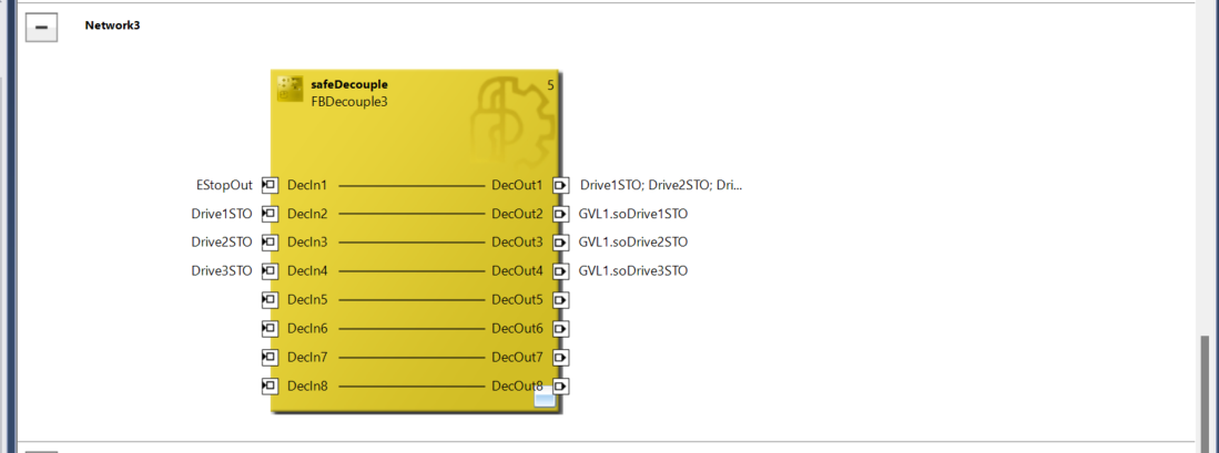
This screen shows the network connection screen for TwinSAFE’s safeDecouple blocks (FBDecouple1, FBDecouple2).
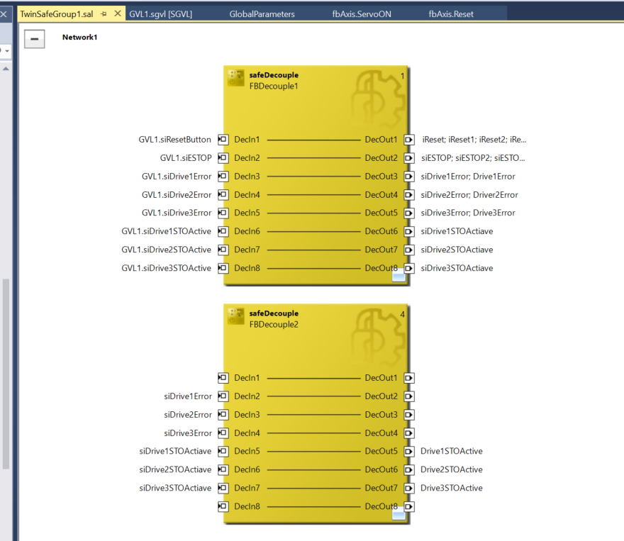
This is the control section for the OMRON STO signal.
The overall flow is:
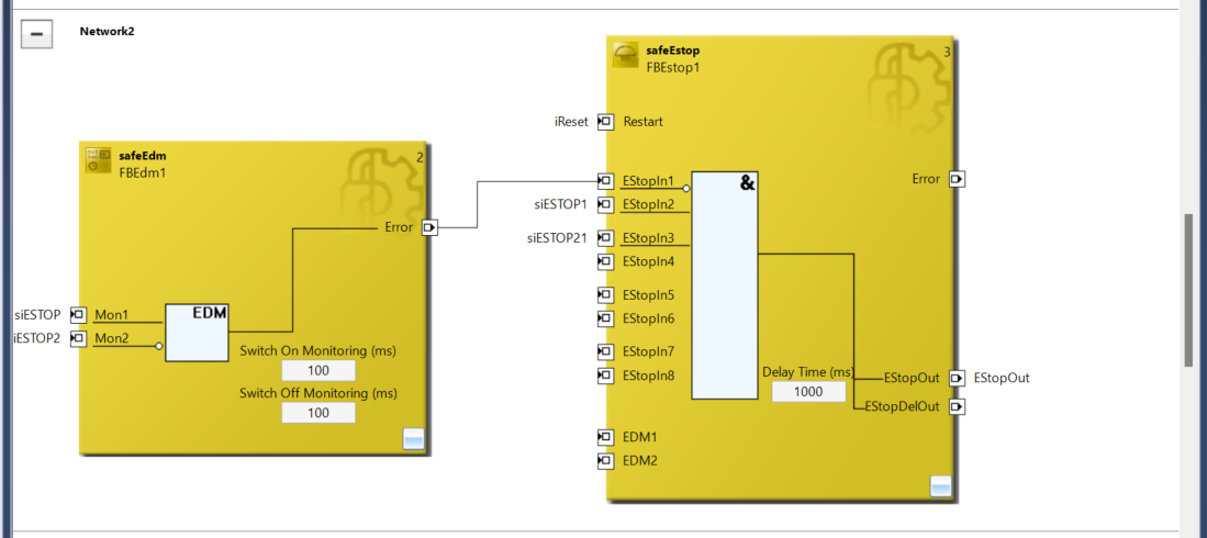
- Monitor siESTOP and siESTOP2 with EDM,
- If there are no issues, input to FBEstop1.
- When conditions are met, turn EStopOut ON immediately and EStopDelOut ON after 1 second.
This is a network for controlling and distributing the STO signals (Safe Torque Off) for three axes when an emergency stop (E-Stop) occurs. Starting from EStopOut, it is configured to collectively cut off STO control for each drive, with output signals mapped to GVL1 variables respectively.
PLC Side
DUT‐dutOMRONR88FSOE
This dutOMRONR88FSOE is a structure (STRUCT) that consolidates the status of the OMRON R88D series FSoE-compatible servo, and is a custom data type defined on the TwinCAT side (standard PLC side).
Field Name | Type | Purpose |
|---|---|---|
xSTOActive | BIT | Whether STO (Safe Torque Off) is active |
xError | BIT | Whether a safety error has occurred in the drive |
xSafetyConnectionStatus | BIT | Whether FSoE communication (Safety over EtherCAT) is established |
TYPE dutOMRONR88FSOE :
|
|---|
GVL
Define the necessary variables in GVL (Global Variable List).
Variable Name | Type / Address | Purpose |
|---|---|---|
ErrorAck | %Q* Output | Error acknowledgment signal from TwinSAFE (transmission to external) |
Run | %Q* Output | RUN signal to TwinSAFE |
MainReset | %Q* Output | Batch reset command from HMI or remote |
stDriveSTO | %I* Input | Safety status of each axis acquired from TwinSAFE side (structure) |
stDriveSTOhmi | Internal variable (no I/O) | Copy of stDriveSTO formatted for HMI display/control |
{attribute ‘qualified_only’}
|
|---|
MAIN
Next is the MAIN program. Set names for each axis (Axis1 to Axis3), apply fbAxis (axis control FB) to each, and copy the STO information acquired from TwinSAFE for HMI display.
PROGRAM MAIN
|
|---|
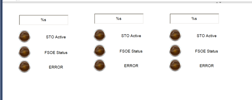
Visualization
FSOE
Create a screen to monitor STO status on the HMI. Each column corresponds to one axis (Axis1 to Axis3), showing respectively:
- STO Active: Whether STO (Safe Torque Off) is enabled
- FSOE Status: Whether the FSoE link (communication) is OK
- ERROR: Whether there is an error in safety communication or status
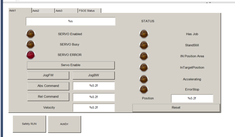
SCREEN
Next, add the FSOE (STO Status) screen as one of the tabs.
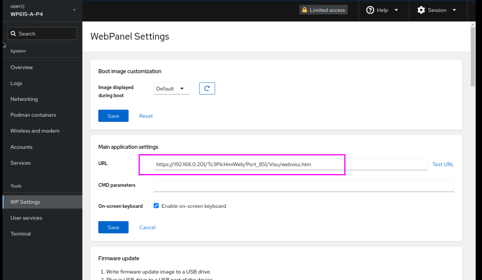
WP615 Web Panel Side
Finally, configure the Pixsys WP615 Web panel.
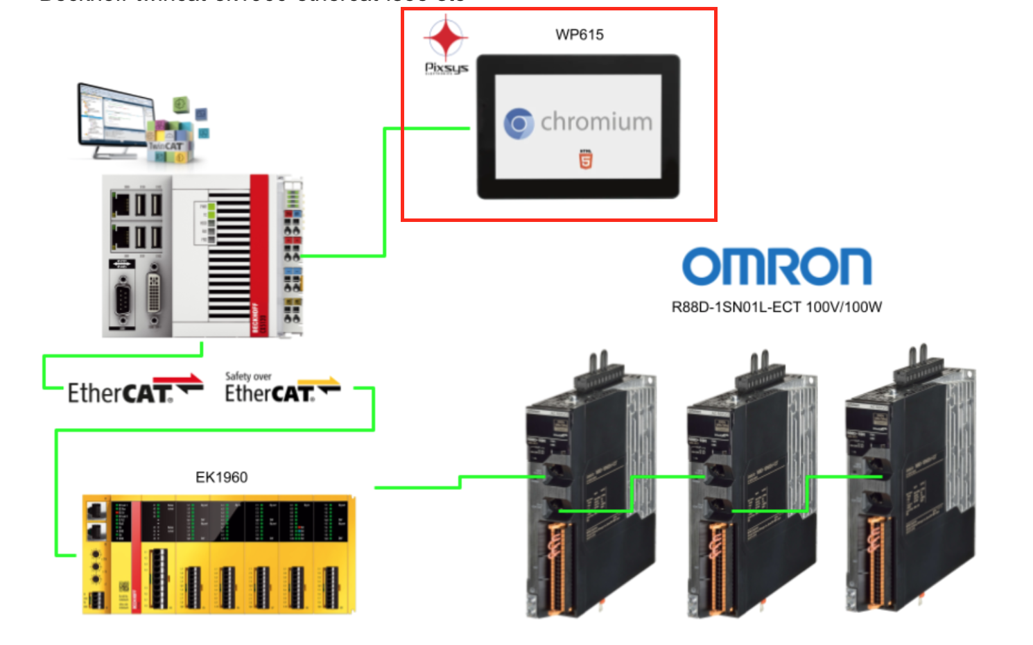
Set WP Setting > URL to the Beckhoff TF1800 URL.
Result
You can verify the actual operation in this video.