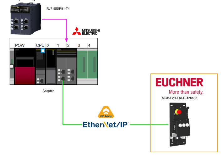
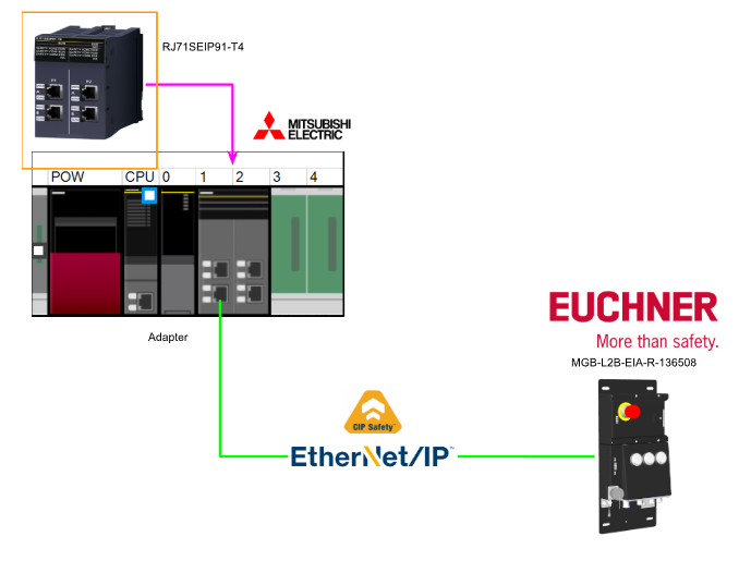
This is a new series of articles in which we will conduct various communication tests using Mitsubishi’s RJ71SEIP91-T4. In this installment, we will build a CIP SAFETY Class communication system from scratch between the RJ71SEIP91-T4 and the Euchner MGB-L2B-EIA-R-136508, and create a safety program using SafetyFB within GXWORKS3.
Alright, let’s enjoy the FA.
Foreword
Thank you from the bottom of my heart for visiting my technical blog and YouTube channel.
We are currently running the “Takahashi Chris” radio show with Full-san (full@桜 八重 (@fulhause) / X) which I deliver every Wednesday night.
Sharing, not hoarding, technical knowledge
We publish technical information related to factory production technology and control systems for free, through blogs and videos.
With the belief that “knowledge should be accessible to everyone,” we share practical know-how and real-world troubleshooting cases from our own field experience.
The reason we keep it all free is simple: to help reduce the number of people who struggle because they simply didn’t know.
If you’ve ever thought:
- “Will this PLC and device combination actually work?”
- “I’m having trouble with EtherCAT communication—can someone test it?”
- “I want to try this remote I/O, but we don’t have the testing environment in-house…”
Feel free to reach out!If lending equipment or sharing your configuration is possible, we’re happy to verify it and share the results through articles and videos.
(We can keep company/product names anonymous if requested.)
How can you support us?
Currently, our activities are nearly all unpaid, but creating articles and videos takes time and a proper testing environment.If you’d like to support us in continuing and expanding this content, your kind help would mean a lot.
Membership (Support our radio show)
This support plan is designed to enhance radio with Mr Full.
https://note.com/fulhause/membership/join
Amazon Gift List (equipment & books for content production)
Lists equipment and books required for content creation.
https://www.amazon.co.jp/hz/wishlist/ls/H7W3RRD7C5QG?ref_=wl_share
Patreon (Support articles & video creation)
Your small monthly support will help to improve the environment for writing and verifying articles.
https://www.patreon.com/user?u=84249391
Paypal
A little help goes a long way.
https://paypal.me/soup01threes?country.x=JP&locale.x=ja_JP
Just trying to share things that could’ve helped someone—if only they’d known.
Your support helps make knowledge sharing more open and sustainable.
Thank you for being with us.
soup01threes*gmail.com
Technical knowledge shouldn’t be kept to ourselves.
Reference Link
Reference Video
OMRON.Let’s Connect with Turck’s CIP Safety IO
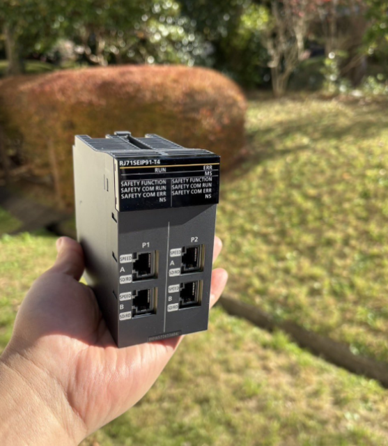
Mitsubishi.Open box with RJ71SEIP91-T4!
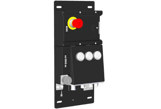
MGB-L2B-EIA-R-136508
This is the CIP Safety door lock used in this article: the Euchner MGB-L2B-EIA-R-136508 (Order No. 136508).
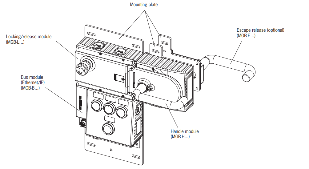
Layout
This is the layout for MGB-L2B-EIA-R-136508 (Order No. 136508).
DIP Switch Settings
These are the DIP switch settings for the MGB-L2B-EIA-R-136508 (Order No. 136508).
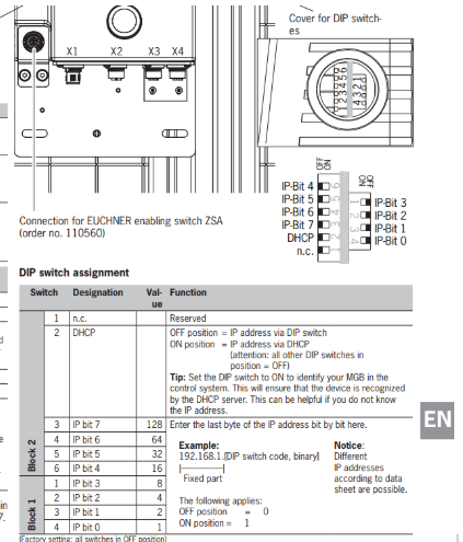
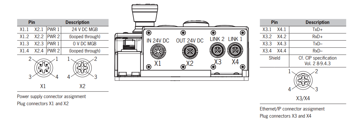
Connections, variant M12
The bus module includes Ethernet/IP connections (X3 and X4) and power connections (X1 and X2). Connections are made using M12 plugs (Ethernet/IP M12 D-code, power M12 A-code). It also features an Ethernet/IP switch for Ethernet connections.
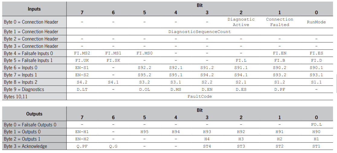
Ethernet/IP data bytes
The MGB system includes the following modules.
- Bus module, MGB-B-…EI (includes everything needed for Ethernet/IP connectivity)
- Lock module, MGB-L. (Forms the door lock mechanism together with the handle module)
In addition, each MGB module occupies a certain number of data bytes within the control system’s input/output range, and the following data types are distinguished:
- Safety data
- Non-safety data
M+SF_GLOCK_R
This is a function block that controls the guard lock and monitors its position. This function block can be used in conjunction with a mechanical lock switch, allowing the operator to request access to the hazardous area. The guard lock can only be released when the hazardous area is in a safe state.
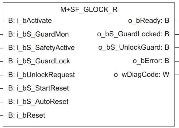
VAR_INPUT
Variable Name | Type | Description |
|---|---|---|
i_bActivate | Bit | 1 = Activate the FB |
i_bS_GuardMon | Bit | Monitor guard interlock / 0: Guard open / 1: Guard closed |
i_bS_SafetyActive | Bit | Status of hazardous area / 0: Machine is in “unsafe” state / 1: Machine is in safe state |
i_bS_GuardLock | Bit | Lock status of mechanical guard / 0: Guard is not locked / 1: Guard is locked |
i_bUnlockRequest | Bit | Unlock command / 0: No request / 1: Request active |
i_bS_StartReset | Bit | Selects reset method for startup (initial) safety FB reset |
i_bS_AutoReset | Bit | Selects reset method to reset by turning input signal ON |
i_bReset | Bit | Reset input |
VAR_OUTPUT
Variable Name | Type | Description |
|---|---|---|
o_bReady | Bit | Indicates whether the safety FB is active |
o_bS_GuardLocked | Bit | Interface to hazardous area requiring machine stop / 0: Not in safe state / 1: Safe state (guard is closed and locked, machine can be operated) |
o_bS_UnlockGuard | Bit | Guard unlock command / 0: Close guard / 1: Unlock guard |
o_bError | Bit | 1 = Error present |
o_wDiagCode | Word [signed] | Diagnostic code |
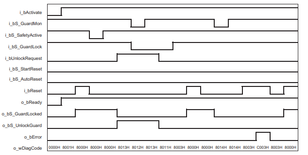
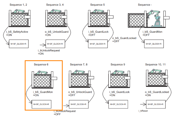
Flow
This is the Flow for M+SF_GLOCK_R.
Sequence
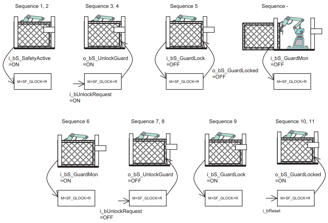
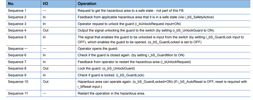
Sequence 1, 2
We will verify that the hazardous area is currently safe and provide feedback confirming that the relevant hazardous area is safe.
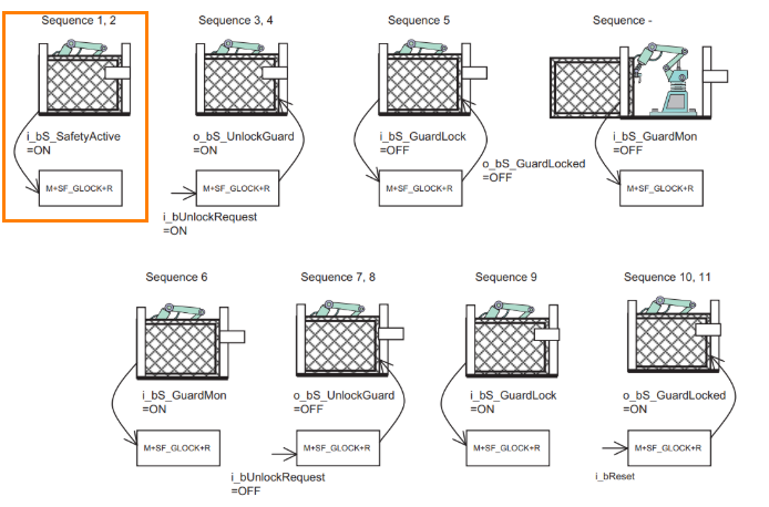
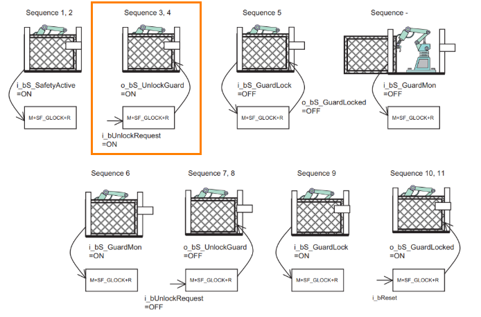
Sequence 3,4
The operator issues a guard unlock request (i_bUnlockRequest input=ON), and the system outputs a guard unlock signal (sets o_bS_UnlockGuard to ON).
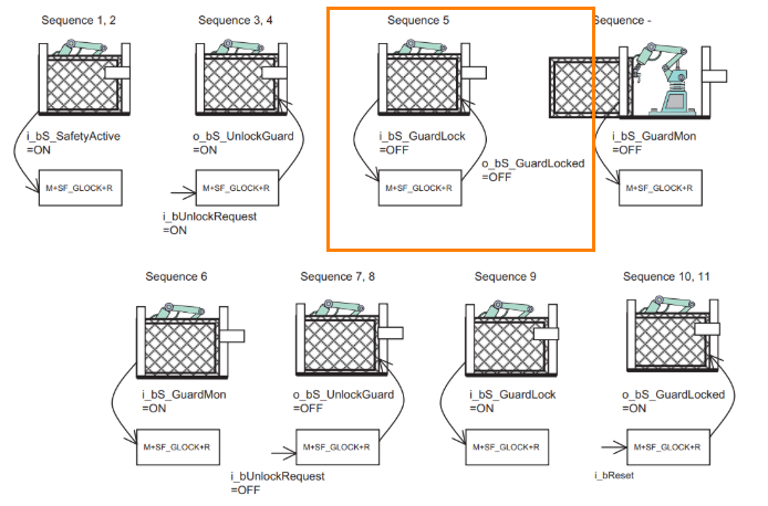
Sequence 5
When a signal indicating that the guard lock has been released is received (i_bS_GuardLock input OFF), the guard can be opened (o_bS_GuardLocked input OFF).
Sequence 5.5
The operator will open the gate.
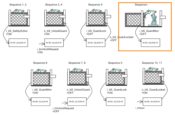
Sequence 6
Check whether the guard is closed again. (Set i_bS_GuardMon to ON)
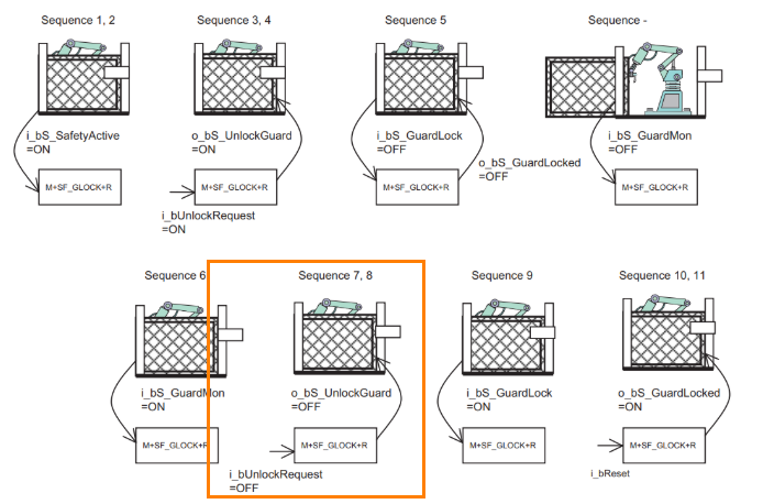
Sequence 7,8
Request the operator to reopen the hazardous area. (i_bUnlockRequest=ON) This will lock the guard. (o_bS_UnlockGuard=ON)
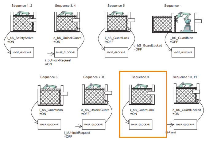
Sequence 9
Check whether the guard is locked (i_bS_GuardLock=ON).
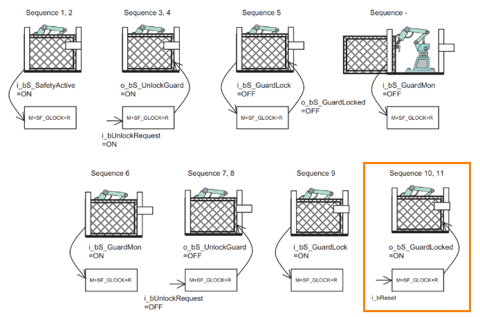
Sequence 10,11
The hazardous area is ready for operation again. (o_bS_GuardLocked=ON)
Note: If i_bS_AutoReset is OFF, a reset via the i_bReset input is required.
Implementation
We will now set up the CIP Safety connection and develop the safety program.

Euncher Side
First, configure the Euchner MGB-L2B-EIA-R-136508 unit.
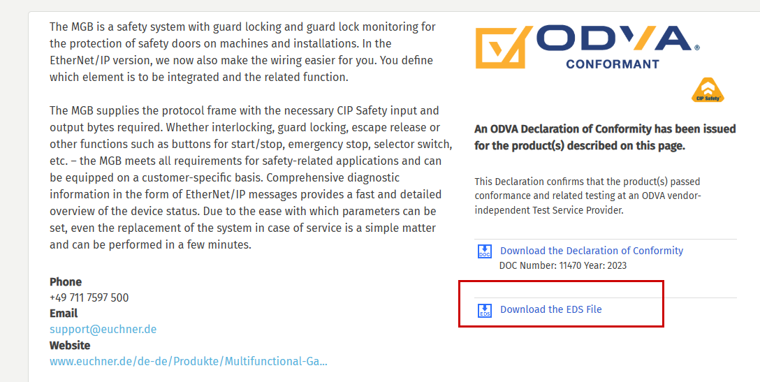
Download EDS File
Please download the EDS file for the Euchner door lock using this link.
https://marketplace.odva.org/products/1872-mgb-with-ethernet-ip
Factory Reset
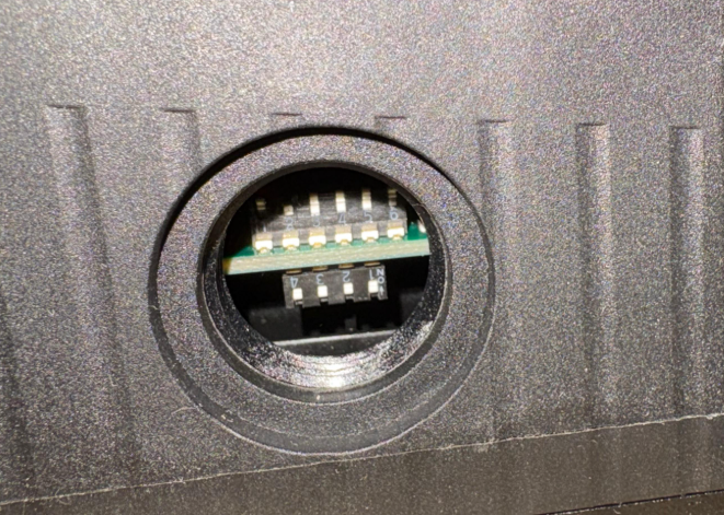
Please open the cover on the right side of the MGB-L2B-EIA-R-136508.
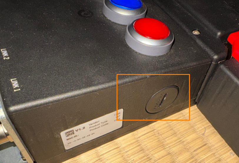
There are DIP switches inside; set all of them to OFF and restart the device.
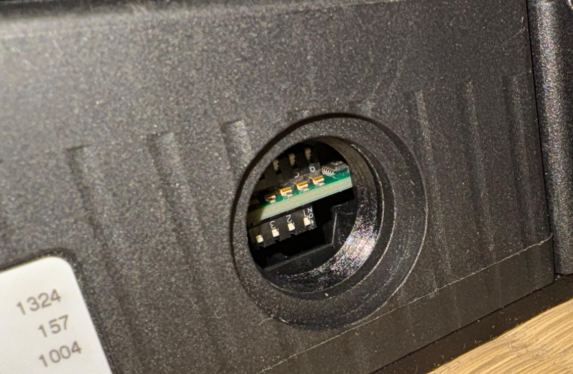
DHCP Server Setting
To configure the door lock as a DHCP server, set only DIP switch 2 to ON.
Mels Side
Next, we will configure the settings for Mitsubishi and the RJ71SEIP91-T4.
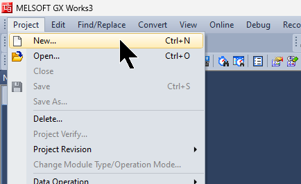
Create New Project
Launch GXWORKS3 and select Project > New to create a new project.
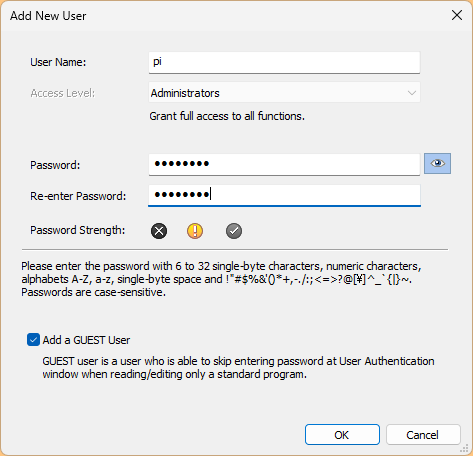
The device used in this article is the R32SF Safety PLC.
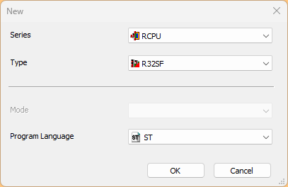
To use the Safety PLC, you must configure the username and password in the project.
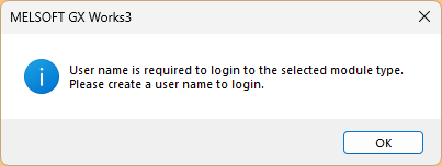
Set your username and password, then click OK to continue.
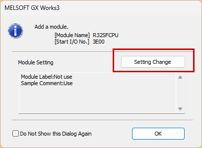
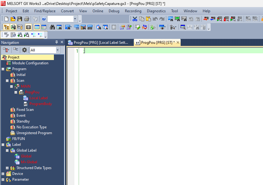
Once the project has been created, click “Setting Change.”
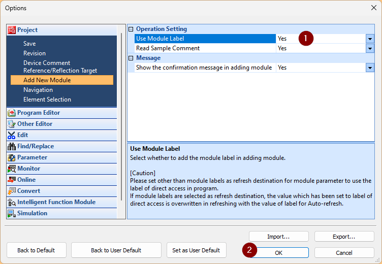
Select the “Use Module Label” option.
Done!The project has been created.
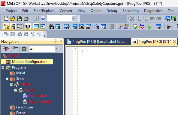
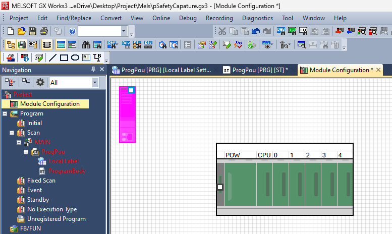
Module Configuration
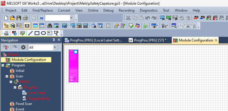
To configure the hardware settings, click Module Configuration.
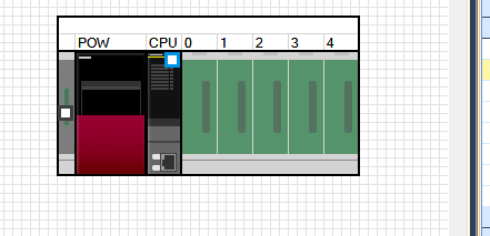
This is the Module Configuration screen.
Add R35B
IQ-R Series > Main Base > Remove the R35B and add the Base Unit used in this article.
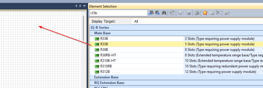
Done!
Add R61P
Next, go to Power Supply > R61P to add the power supply module used in this article.
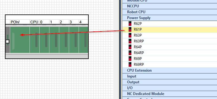
Done!
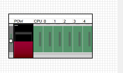
Add PLC into PLC Rack
Insert the R32SF Safety PLC into the CPU slot.
Done!So I installed the CPU in the rack.
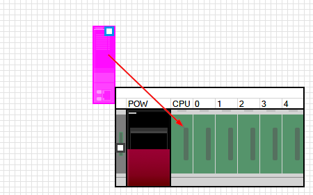
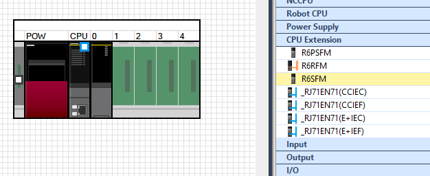
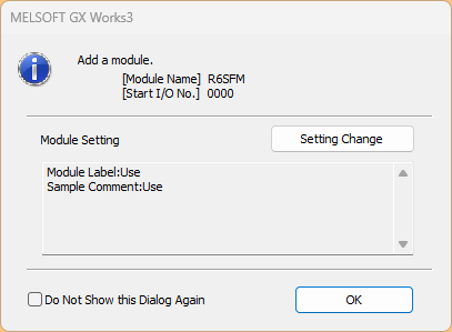
Add R6SFM
Add a CPU safety extension unit via CPU Extension>R6SFM.
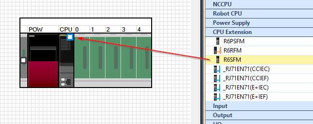
Done!
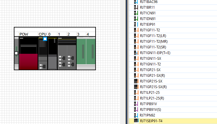
Add RJ71SEIP91-T4
Finally, insert the Network>RJ71SEIP91-T4 into Slot 1.
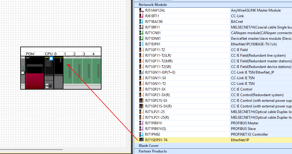
Done!
Save the Configuration
Next, save the Module Configuration.
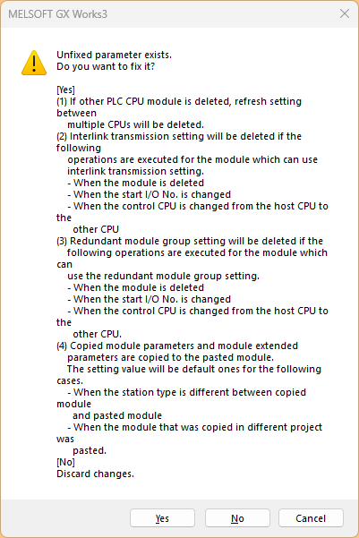
Click OK to continue.
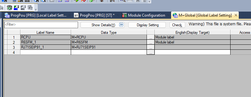
M+Global
Since I enabled the Module Label settings a moment ago, a Global Variable List named “Label>Global Label>M+Global” has been added.
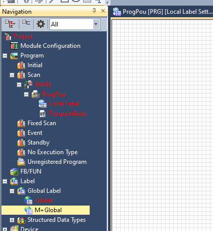
Labels for the CPU and modules (including, of course, the RJ71SEIP91-T4) used in this article have been defined in M+Global.
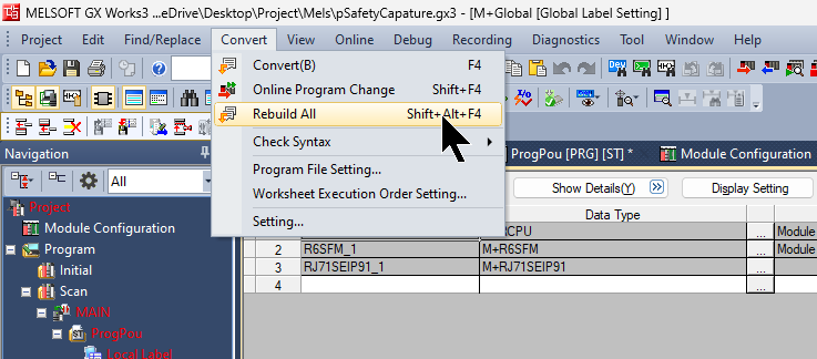
Check your Configuration
Let’s run “Convert > Rebuild All” once to check if there are any issues with the hardware configuration.
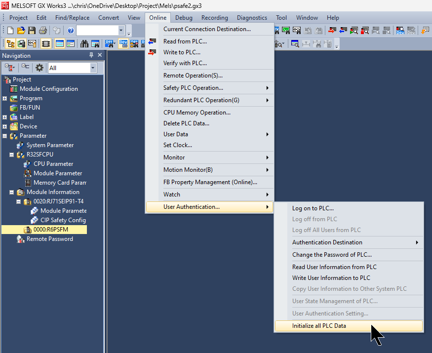
Reset User
If you forget the password for the R32SF Safety PLC unit, initialize the PLC data to reset all data. Click Online > User Authentication > Initialize all PLC Data.
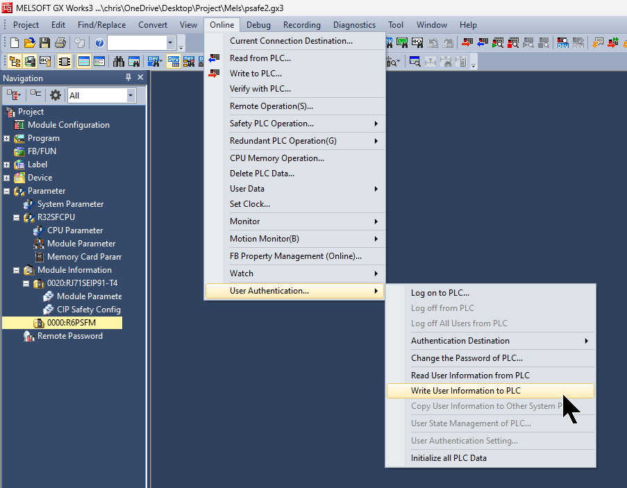
Write User Data
Next, to write the user data for this project to the CPU, we will use Online > User Authentication > Write User Information to PLC to write the user data to the R32SF Safety PLC.
Click “Yes” to continue.
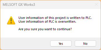
Click “Yes” to continue.
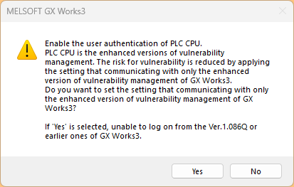
Done!
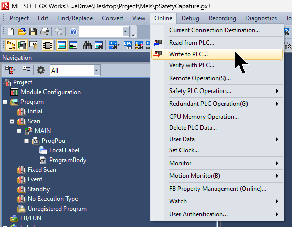
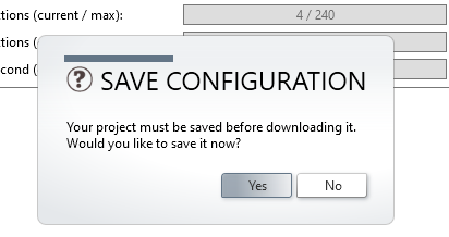
Write to PLC
To temporarily write the hardware configuration to the CPU, please select Online > Write to PLC.
Check RJ71SEIP91-T4 IP Address
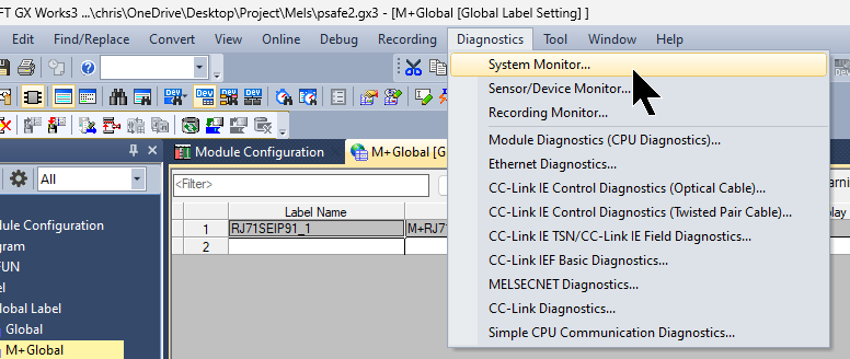
To check the IP address of the RJ71SEIP91-T4, click Diagnosis > System Monitor.
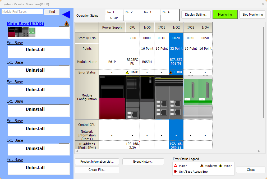
Double-click the RJ71SEIP91-T4 module.
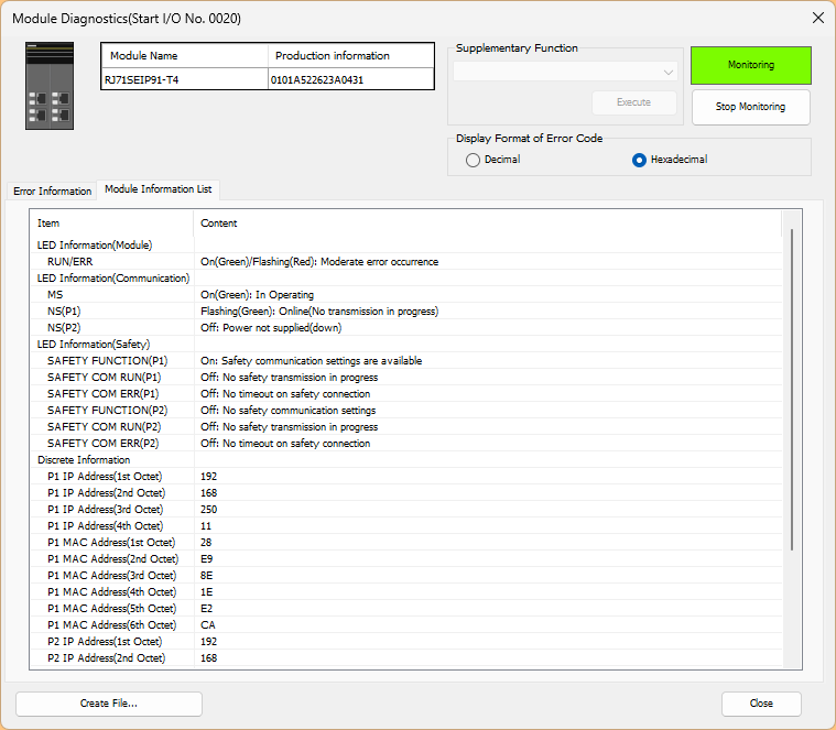
You can view the diagnostic information for RJ71SEIP91-T4 by opening the Module Information List tab.
The details for RJ71SEIP91-T4 were displayed, and I confirmed that P1=192.168.250.11.
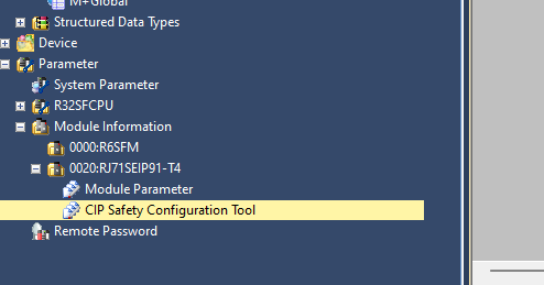
Configure Ethernet/IP Network
Next, to set up an Ethernet/IP network, double-click the RJ71SEIP91-T4>CIP Safety Configuration Tool to launch it.
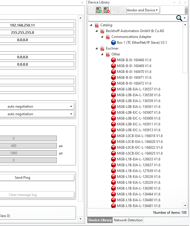
Install EDS File
Install the EDS file via CIP Configuration Tools > Device Library > Add EDS.
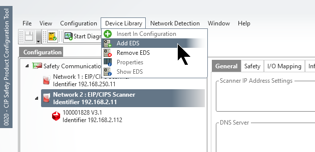
Select “Add EDS From Directory,” then click “Browse” to select the folder where you saved the EDS file you downloaded earlier.
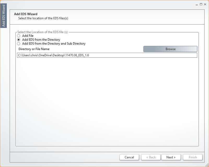
Select the EDS file you want to install, then click >Next> to proceed.
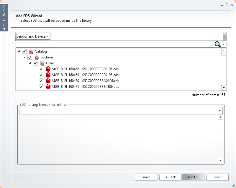
Done!The EDS file has been installed.
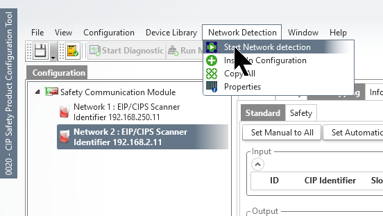
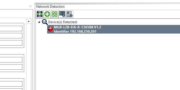
Start Detection
Network Detection > Start Network Detection to scan for Ethernet/IP devices on the network.
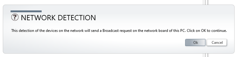
Click OK to continue.
Wait a moment…
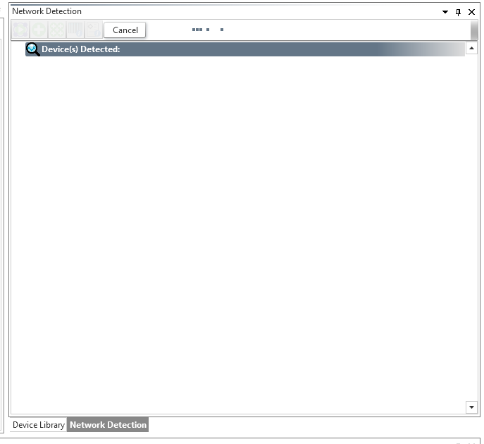
Done!I was able to find the Euchner MGB-L2B-EIA-R-136508.
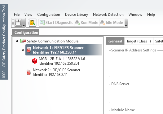
Let’s add the Euchner MGB-L2B-EIA-R-136508 to Network1.
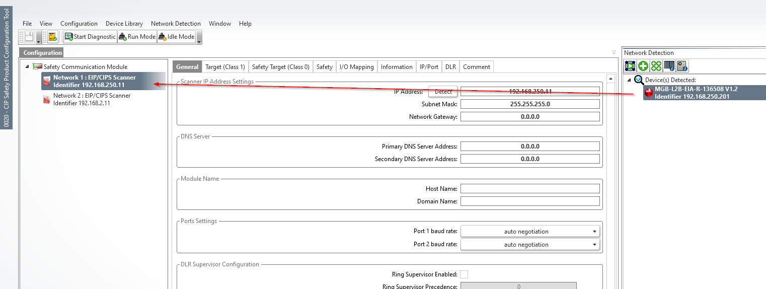
Done!
Safety Settings
Configure the parameters required to establish a Safety Connection.
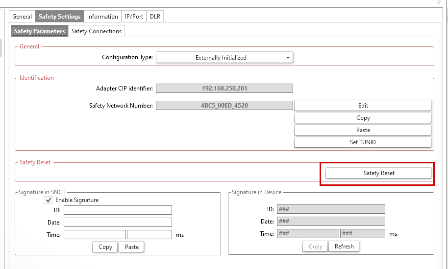
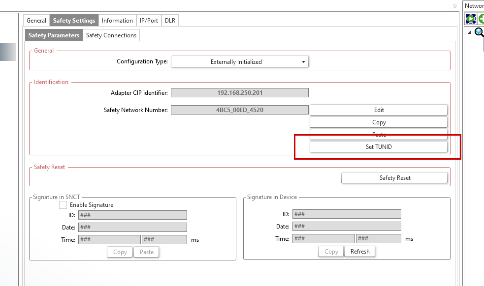
Safety Parameters
Select the Euchner MGB-L2B-EIA-R-136508 you just added, then open the Safety Settings > Safety Parameters tab.
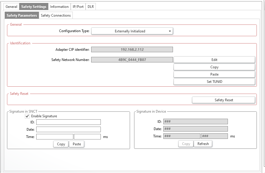
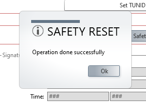
Click “Safety Reset” to reset the TUNID for the Euchner MGB-L2B-EIA-R-136508.
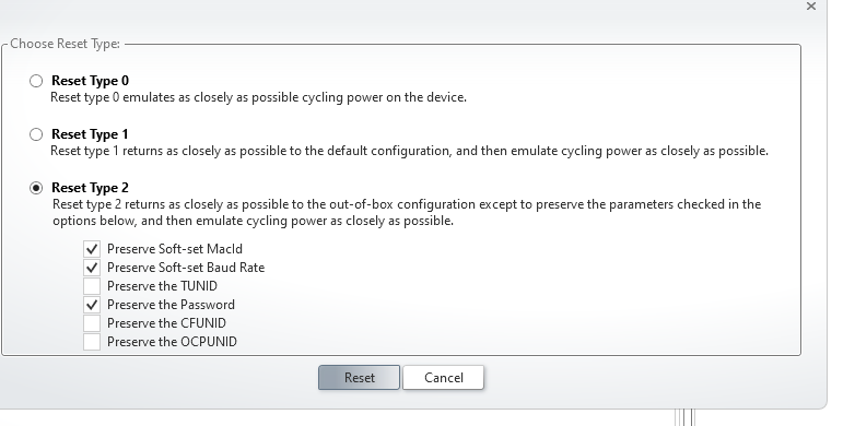
Click “Reset” to continue.
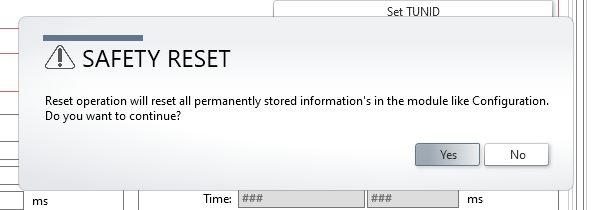
Click “Yes” to continue.
Reset TUNID.
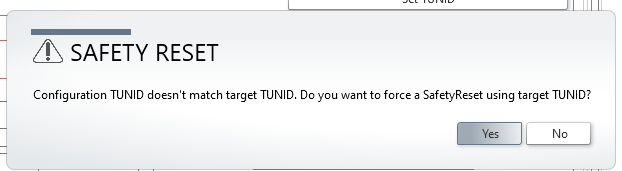
Done!
Set TUNID
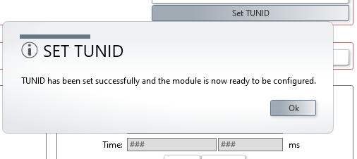
Next, click the “Set TUNID” button to assign a new TUNID ID to the Euchner MGB-L2B-EIA-R-136508.
Done!
Save Configuration
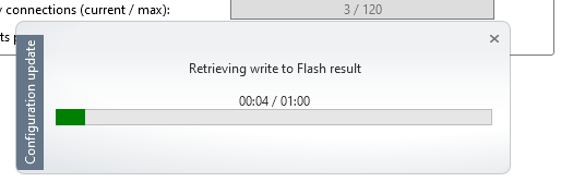
Finally, click “Save Configuration to Module” to apply the changes and upload them to the RJ71SEIP91-T4.
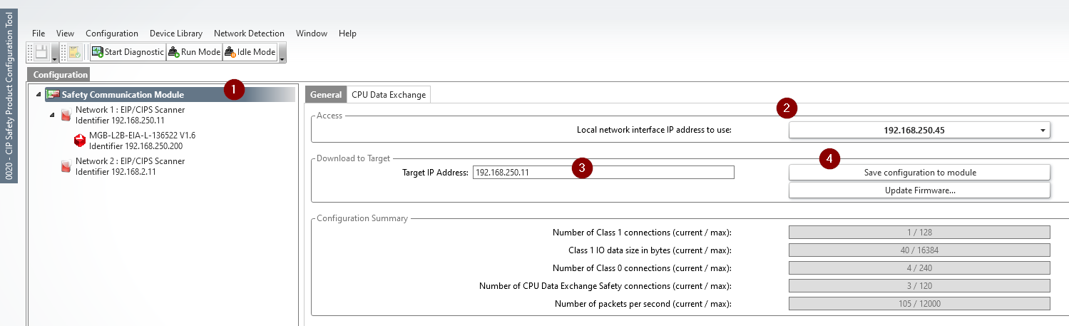
Click “Yes” to save the settings.
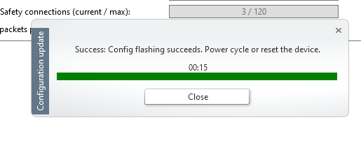
Please wait a moment…
Done!
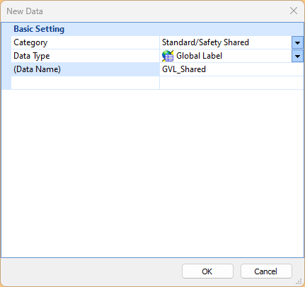
Add Shared GVL
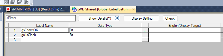
Next, we will add the Standard/Safety Shared Global Label List.
These are the variables for Shared GVL.
Safety GVL
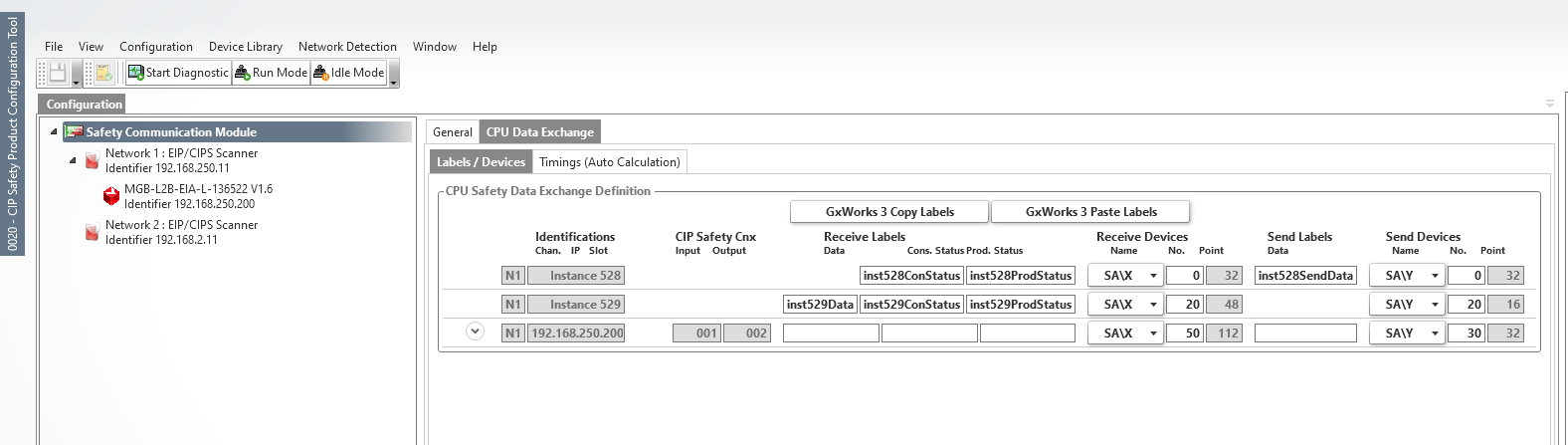
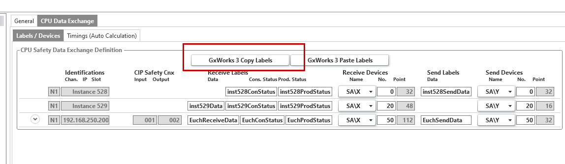
Next, map the Safety I/O data to be exchanged with the Euchner MGB-L2B-EIA-R-136508 in GXWORKS. Click Safety Communication Module > CPU Data Exchange > Label/Devices, and map the appropriate device.
Click “Copy Labels” in GxWorks3.
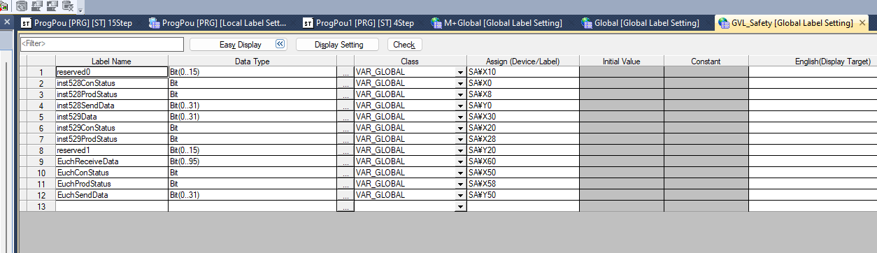
Create a new “Safety GVL” and paste the label by pressing Ctrl+V.
NonSafety-Program
Create an unsafe program.
As shown in the figure below, retrieve the communication start signal and the status of each connection for the RJ71SEIP91-T4.
RJ71SEIP91_1.stEIPCls1_P1.uSet_CommunicationStartupRequest_D:=1;
|
|---|
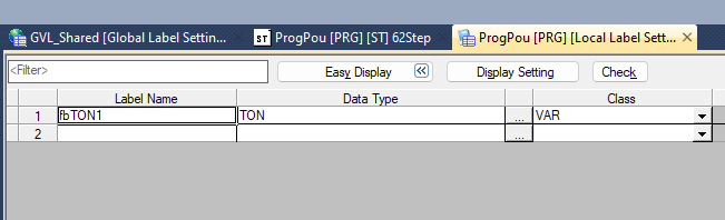
Safety FB
Fb16Bit2Word
This function converts 16 Boolean values into a single Word.
sxIn00 Bit VAR_INPUT
|
|---|
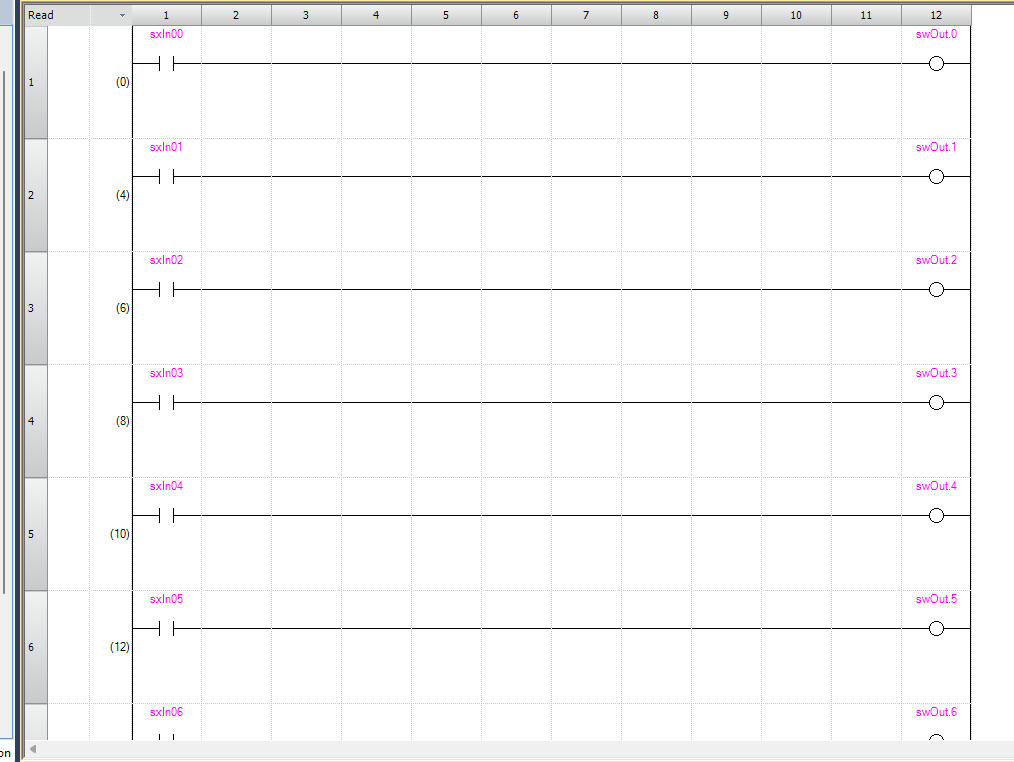
As shown in the figure below, we will configure the system to output each bit to a word.
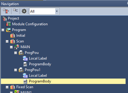
MAIN
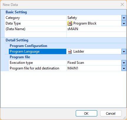
Finally, to create a security program, go to Fixed Scan > Add New Data.
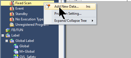
Create a Safety Ladder.
VAR
These are the variables used in the Safety program.
_CommOK Bit VAR
|
|---|
This is the safety program we created for this article.
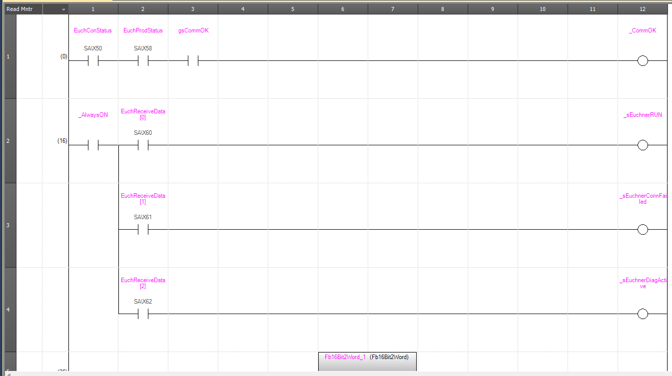
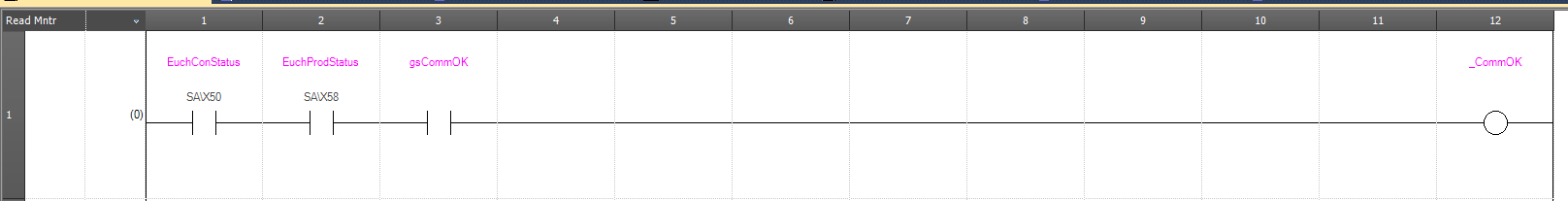
Rung1
Rung1 verifies communication between Mitsubishi’s RJ71SEIP91-T4 and Euchner’s MGB-L2B-EIA-R-136508.
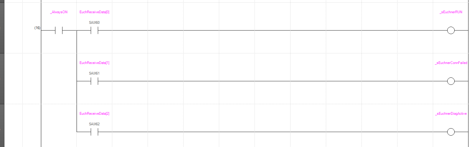
Rung2
Rung2 retrieves the status of the Euchner MGB-L2B-EIA-R-136508 door lock.
Rung5
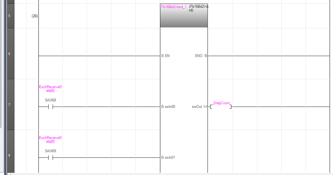
Rung 5 uses the 16-bit-to-Word conversion function block created earlier to retrieve the number of diagnostic events for the Euchner MGB-L2B-EIA-R-136508.
Rung23
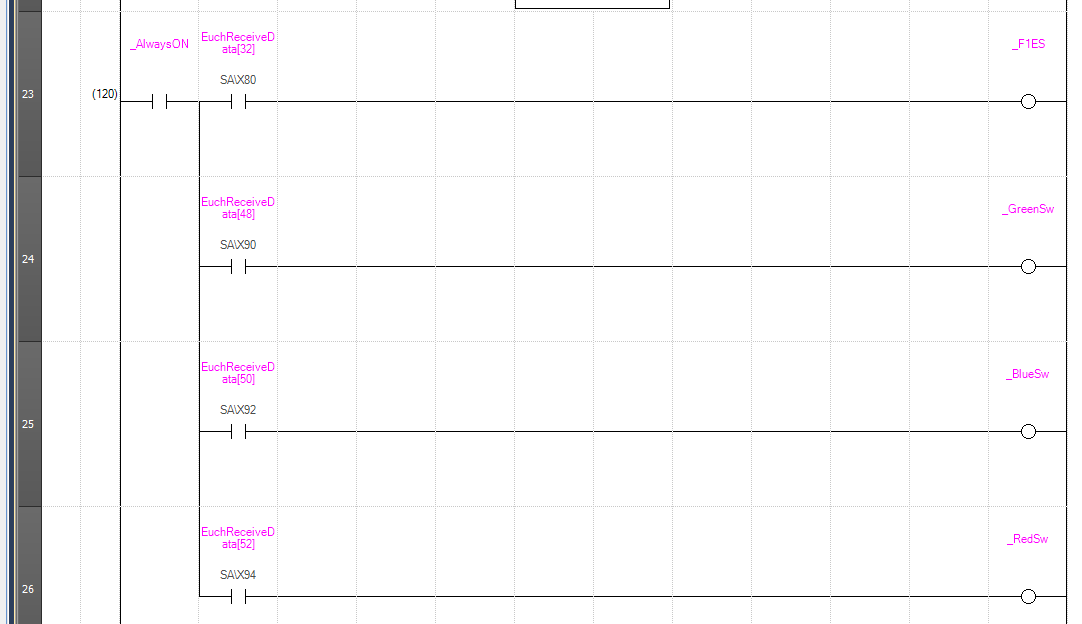
Rung23 retrieves the status of each button and the emergency stop status for the Euchner MGB-L2B-EIA-R-136508.
Rung27
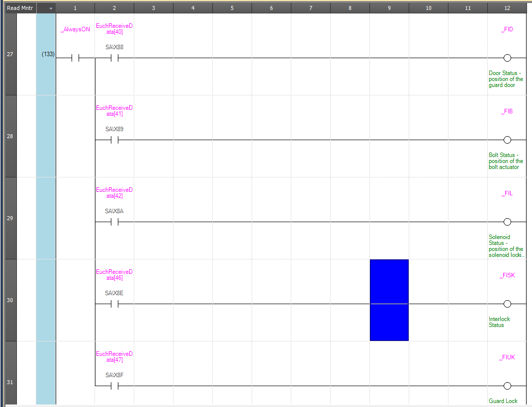
Rung27 retrieves the door status of the Euchner MGB-L2B-EIA-R-136508.
Rung32
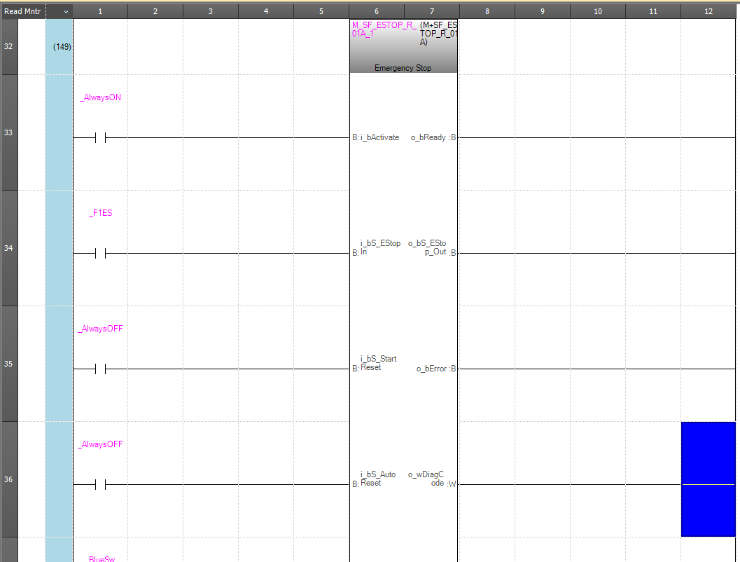
Rung32 uses Mitsubishi’s Safety Function Block to control the emergency stop.
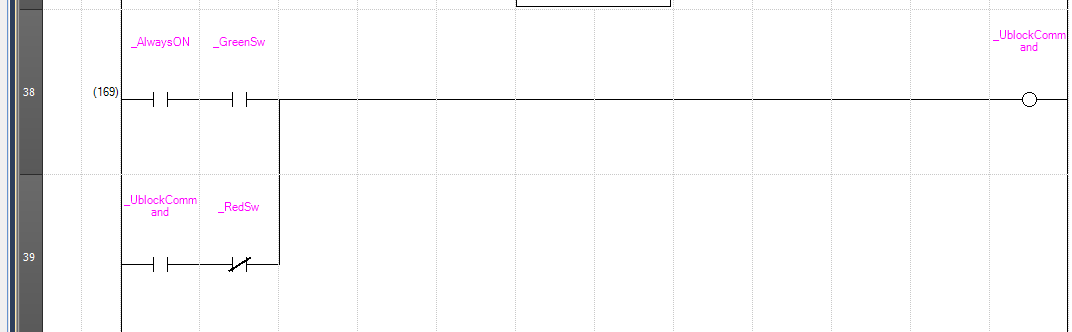
Rung38
Rung38 issues the unlock command for the Euchner MGB-L2B-EIA-R-136508 door lock.
- Press the green button: Unlock
- Press the red button: Lock
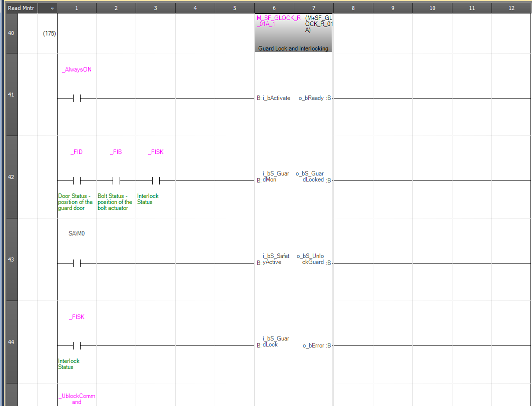
Rung46
In Rung46, we use Mitsubishi’s Safety Function Block to control the door lock on the Euchner MGB-L2B-EIA-R-136508.
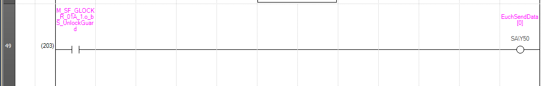
Rung49
Rung49 unlocks the door lock based on the output from the previous Safety Function Block.
TRUE = Unlocks the door.
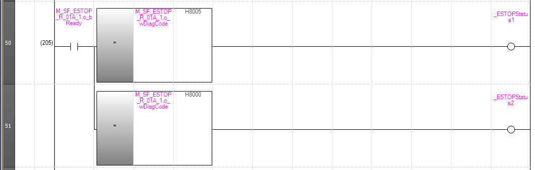
Rung50
Rung50 checks the current status using the diagnostic words of the emergency stop Safety Function Block.
- ESTOP diagnostic word=16#8005=Waiting for reset
- ESTOP diagnostic word=16#8000=Emergency stop OK, Enable signal being output
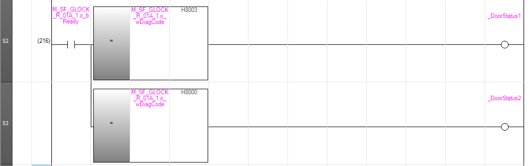
Rung52
Rung52 checks the current status using the diagnostic words in the door lock’s Safety Function Block.
- Door Lock Diagnostic Word=16#8003=Waiting for reset
- Door Lock Diagnostic Word=16#8000=Emergency stop OK, Enable signal being output
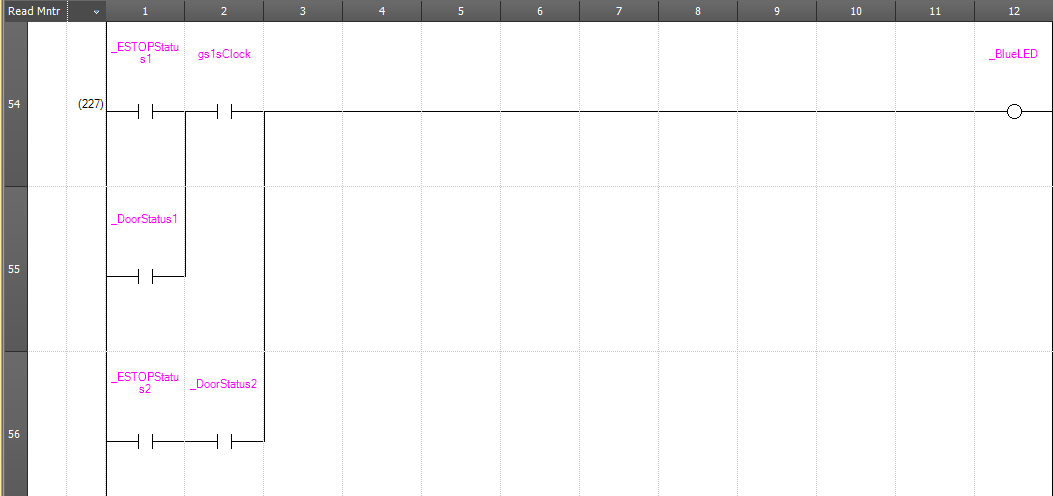
Rung54
Depending on the status of the safety device, Rung54 outputs either a steady or flashing blue light.
- Flashing = Waiting for reset
- Solid light = All safety devices are in normal condition
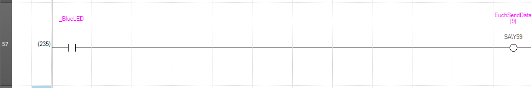
Rung57
Rung57 outputs the blue pushbutton lamp from Euchner’s MGB-L2B-EIA-R-136508.
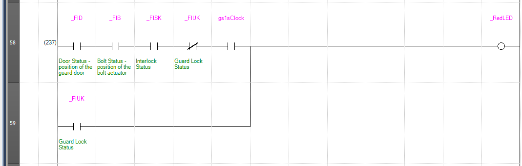
Rung58
The red indicator light on the Rung58 flashes or stays lit depending on the status of the door lock.
- Red flashing: The door lock is in the correct position and awaiting reset;
- Red steady: The door lock is locked
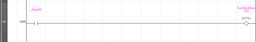
Rung60
Rung60 outputs the red pushbutton lamp for the Euchner MGB-L2B-EIA-R-136508.
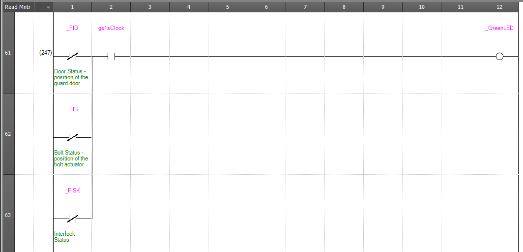
Rung61
When unlocking the door, Rung61 outputs a signal by flashing the green button light.
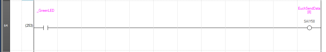
Rung64
Rung64 outputs the green pushbutton lamp for the Euchner MGB-L2B-EIA-R-136508.
Result
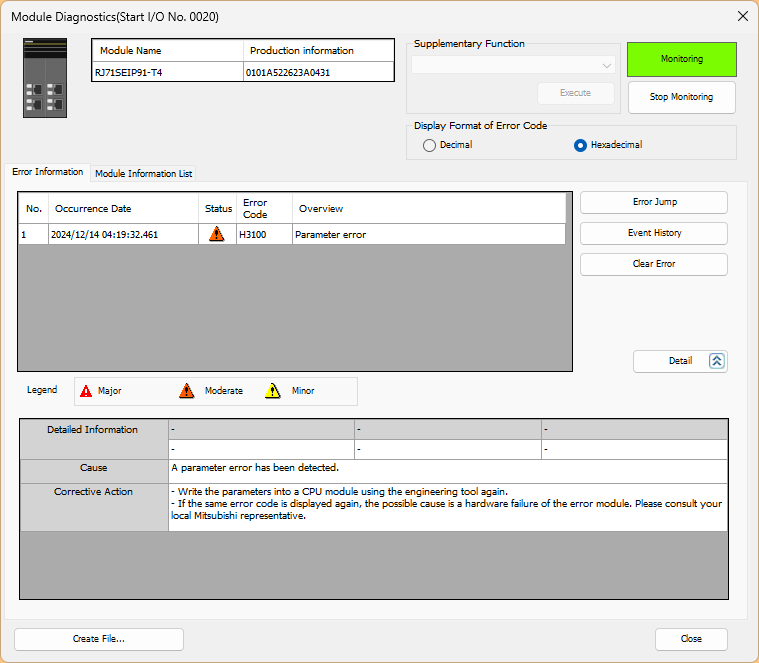
First, an error message was received from the CIP CM Protocol, and the connection cannot be established because the revisions do not match.
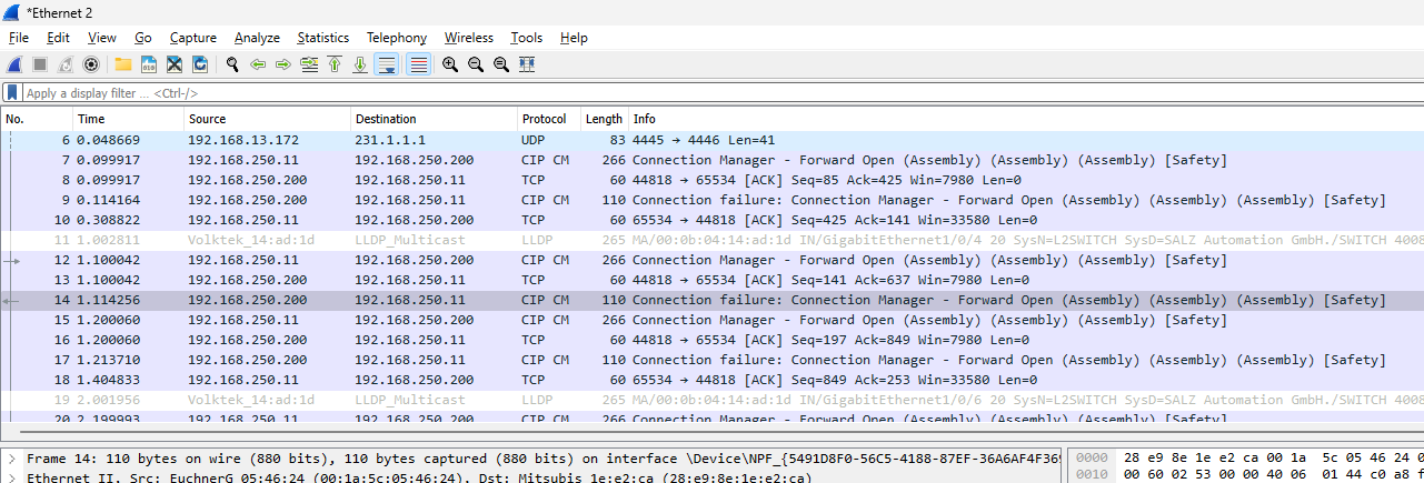
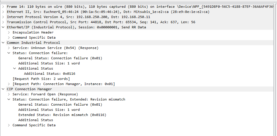
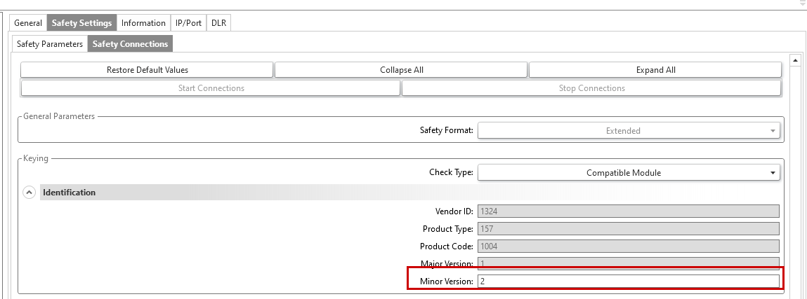
To resolve this error, either replace the EDS file or configure Safety Connections as follows.
- Check Type:Compatible Module
- Minor Version:2(EuchnerのMGB-L2B-EIA-R-136508のMinor Version)
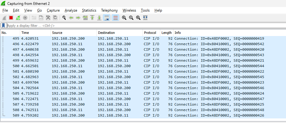
Done!CIP I/O messages can now be exchanged.
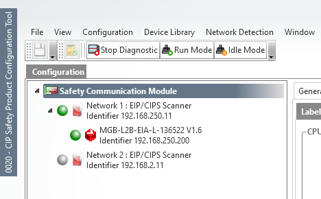
You can see that communication has been established with the CIP Safety Configuration tool in Mitsubishi GXWorks3.
You can see how it works in this video.
Mitsibushi.CIP Safety Module RJ71SEIP91-T4 With Euchner Door Lock
Download
Please use this link to download the project created in this article.