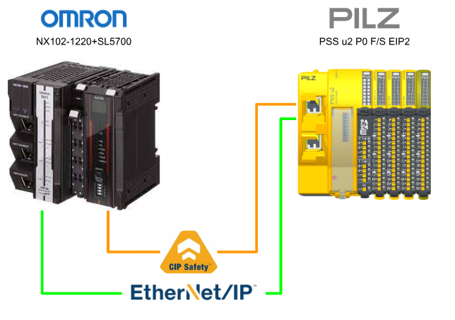
This article presents a Step by Step introduction to CIP Safety connections and Normal Ethernet/IP connections using Pilz’s PSS u2 P0 F/S EIP2 CIP Safety module in combination with OMRON’s NX102-1220 and SL5700.
We will also explain how to generate the Safety EDS File in Sysmac Studio, which is the most difficult thing for everyone, by looking at the EZ-EDS tool.
Note that the article will be extremely long, so Part 1 will first explain how to build a CIP Safety network, and Part 2 will actually write about how to make the program in NX CPU.
Let’s get started!
Reference Link
Thanks!
This article was made possible thanks to Omron Corporation and Pilz Japan. for lending us their equipment. Thank you very much.
オムロン株式会社
As a leading automation company, OMRON Corporation develops a wide range of businesses, including control equipment mainly for factory automation, electronic components, social systems such as automatic ticket gates at railway stations and power conditioners for solar power generation, and healthcare, and provides products and services in some 120 countries and regions. The company provides products and services in some 120 countries and regions.
This is the website of Omron Corporation.

PILZ
PILZ supports FA sites as a total solution supplier with solutions in safety and automation technology, guaranteeing the safety of people as well as machines and the environment, and how safely machines and equipment can be operated. PILZ has 42 subsidiaries and branches worldwide and is active in various sectors such as packaging, the automotive industry, robotic applications, as well as wind power and railway technology.
Office:
ピルツジャパン株式会社
〒222-0033
横浜市港北区新横浜3-17-5
いちご新横浜ビル 4階
HP

PSS u2 P0 F/S EIP2?
The PSS u2 P0 F/S EIP2 is only available on PSS u2 systems and is designed for safety-related applications such as
- CIP Safety via EtherNet/IP
- non-safety-related applications with EtherNet/IP
- EN IEC 61508 up to SIL CL 3
- In accordance with EN 298

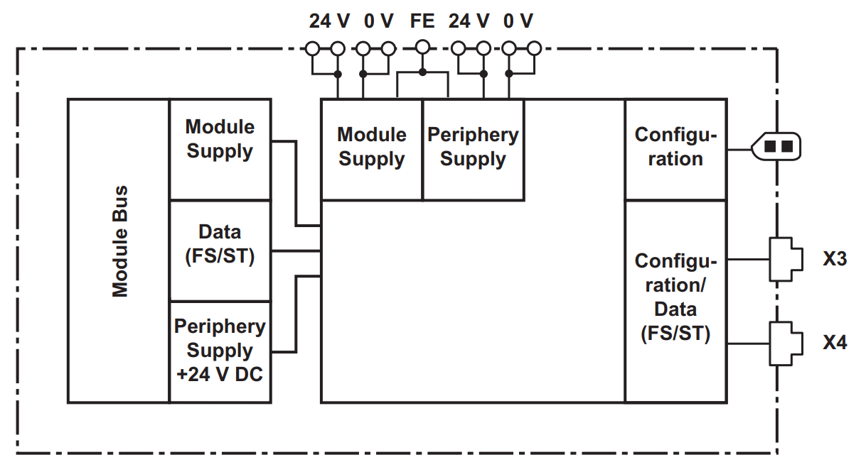
Block Diagram
This is the internal block diagram of the PSS u2 P0 F/S EIP2.
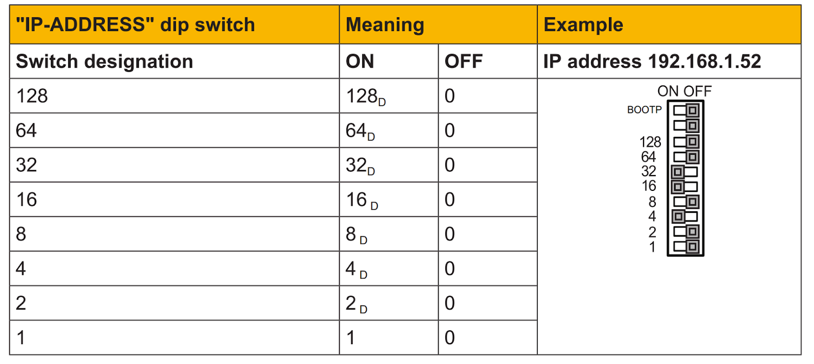
IP address
The IP address can be set via Static and DHCP from the DIP switch.
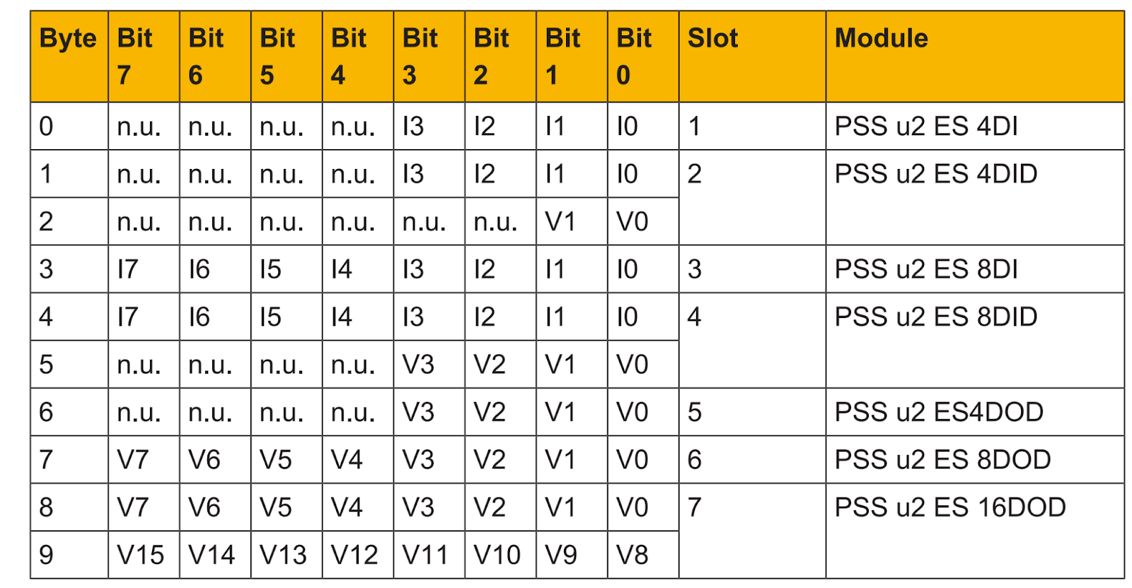
ST process image
ST is used as standard input/output data.
- Instance 101 of Assembly Object (0x04) is Process Images of ST output.
- Instance 104 of Assembly Object (0x04) is Process Images of ST input.
- Heartbeat Instance of Assembly Object (0x04) is 198.
- Listen Only Instance of Assembly Object (0x04) is 198.
Note that the length of the STProcess data depends on the number of ST modules configured. The Process Image for a module occupies at least one byte. (even if not all bits are used).
ST Inputs
The valid bits of the ST output are also transferred to the Process Image on the ST input.
- I: Input
- n.u.: not used
- V: Valid bit
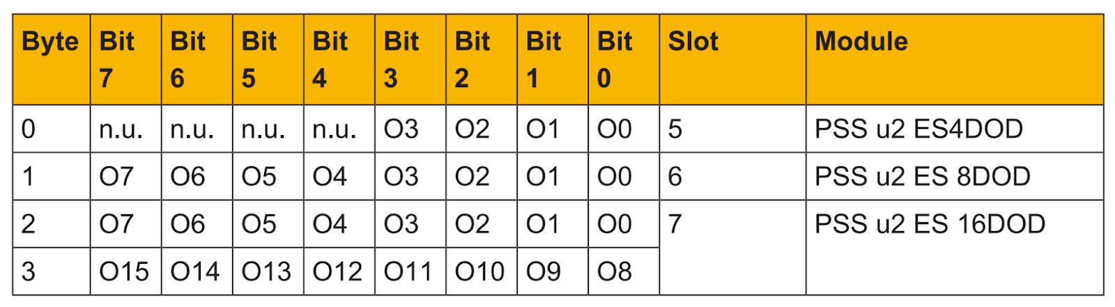
ST Outputs
These are Process Images of the ST output.
- O: Output
- n.u.: not used
CIP Safety
PSS u2 P0 F/S EIP2 can be used with up to 24 FS modules.
FS process image of inputs
This is safety data.
- Instance 772 of Assembly Object (0x04) is a safety input Process Images.
- Process Images included in CIS and allocated to Byte 0.
- CIS=Combined Input State
- CIS=0, not all FS input modules provide valid values
- CIS=1, all FS input modules provide valid values
- CIS=Combined Input State
- Included in COS in Process Images and allocated to Byte 1.
- COS=Combined Output State
- COS=0, not all FS input modules provide valid values
- COS=1, all FS input modules provide valid values
- COS=Combined Output State
FS process image of outputs
This is safety data.
- Instance 769 of Assembly Object (0x04) is the safe output Process Images.
It is important to note that the FS Process Images for the output cannot be empty; if the FS Output module is not used in the project, the Head module will automatically create the FS output data.
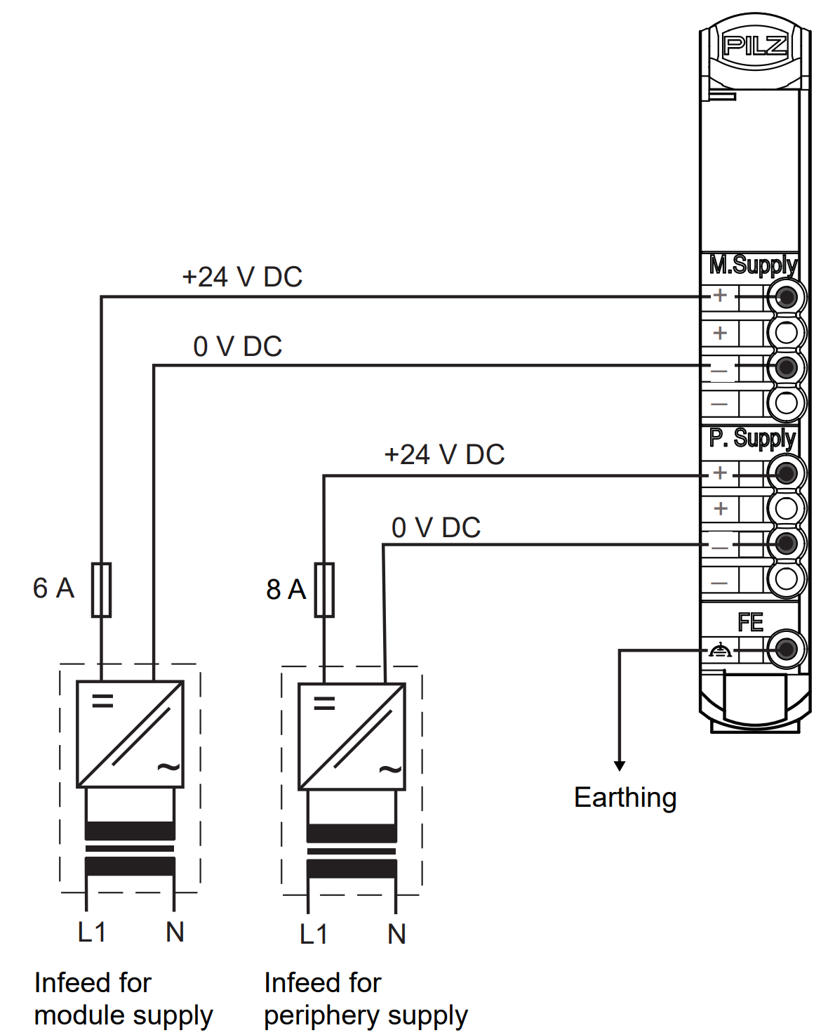
Connections
This is the power supply diagram for PSS u2 P0 F/S EIP2 (separate power source).
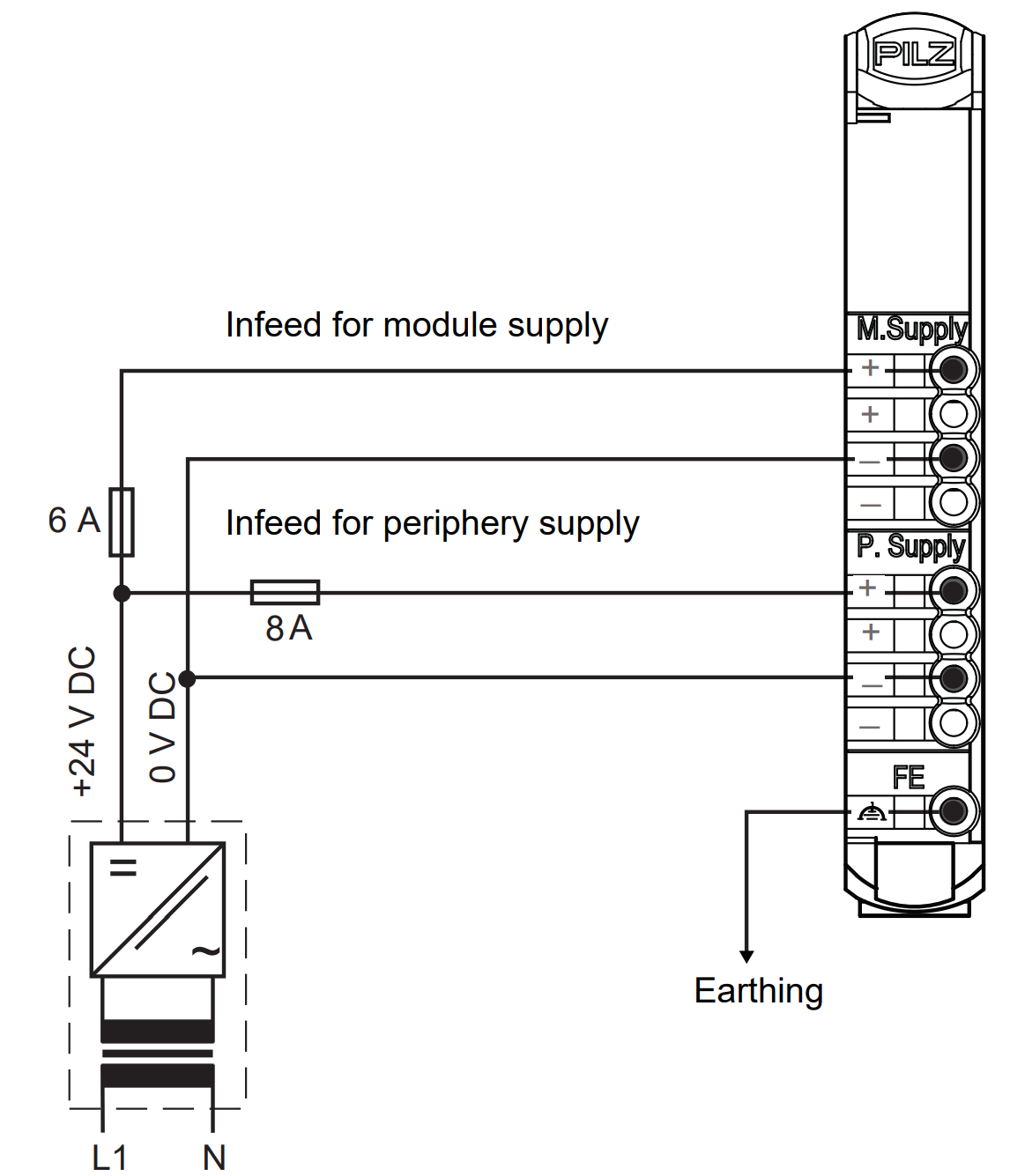
This is the power supply diagram for the PSS u2 P0 F/S EIP2 (shared power supply).
Implementation
We will now actually build it Step By Step.
Pilz Side
The first step is the Pilz side.
Install PASConfig
You can also download the PASConfig software from the Link below.
New Project
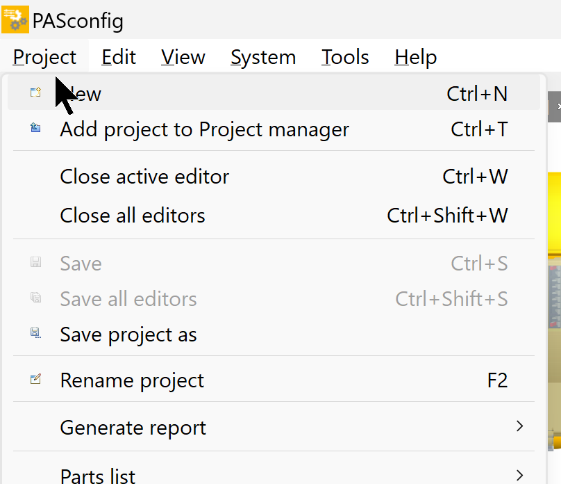
Start PASConfig and create a new project under Project>New.
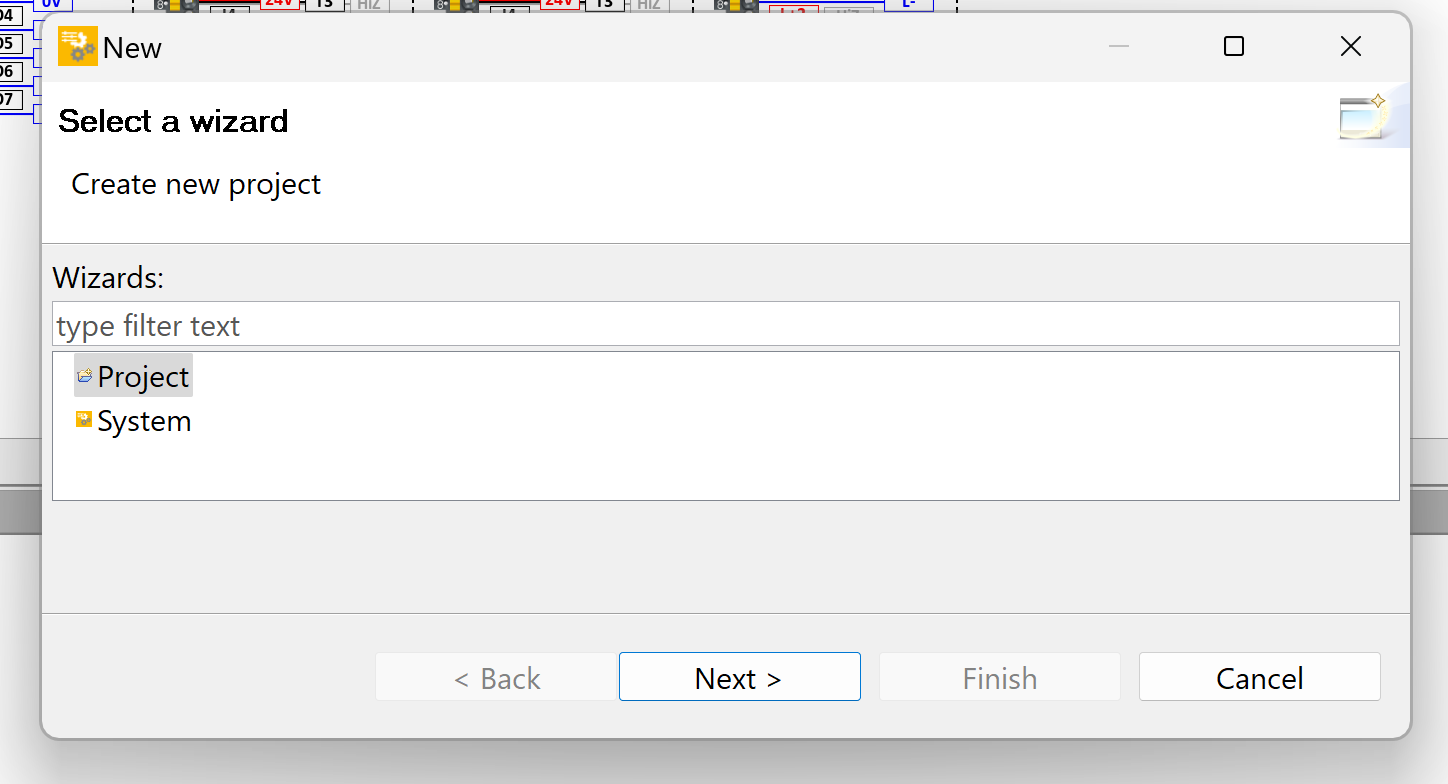
Select Project and press Next> to proceed.
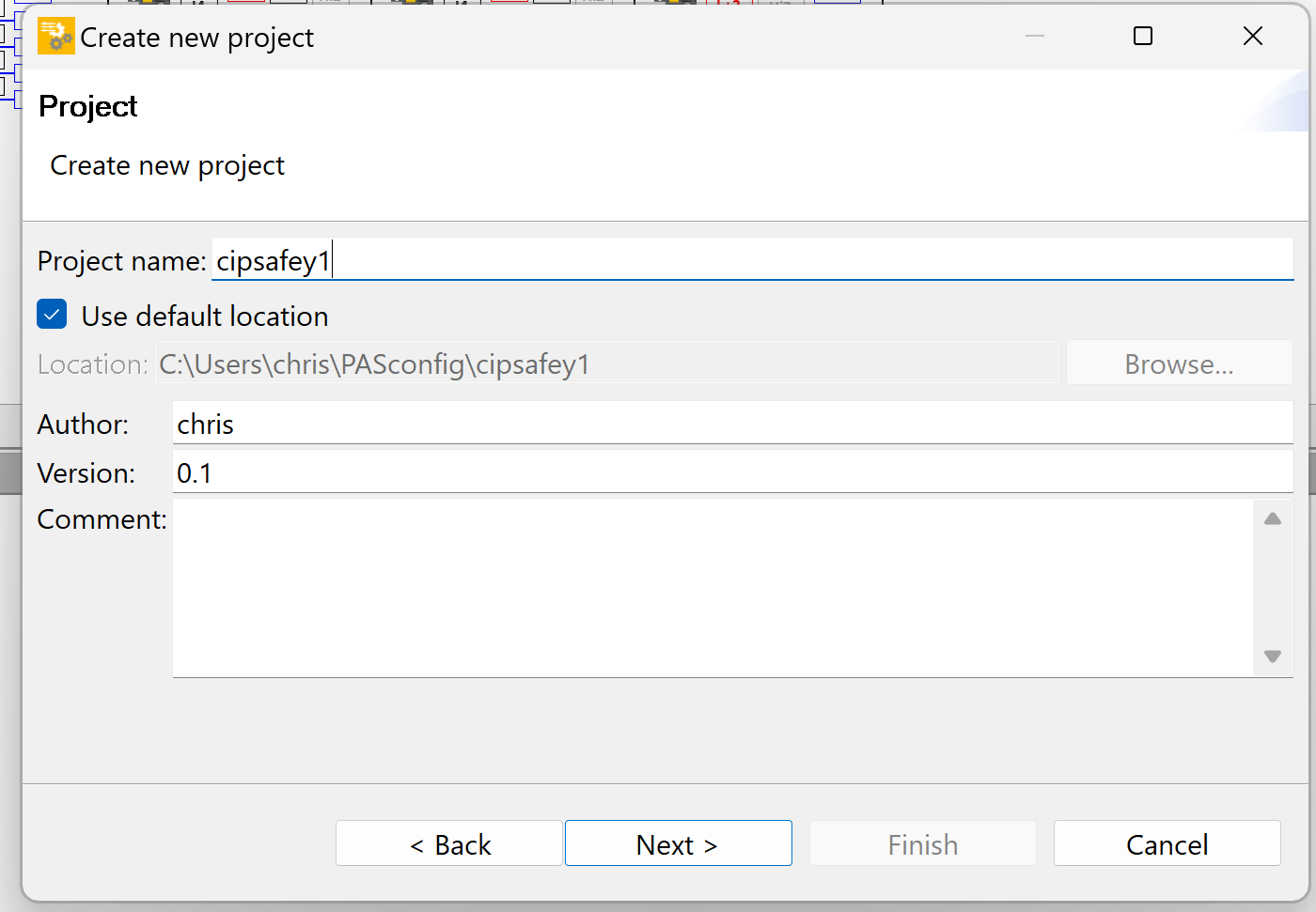
Set the Project name and proceed with Next>.
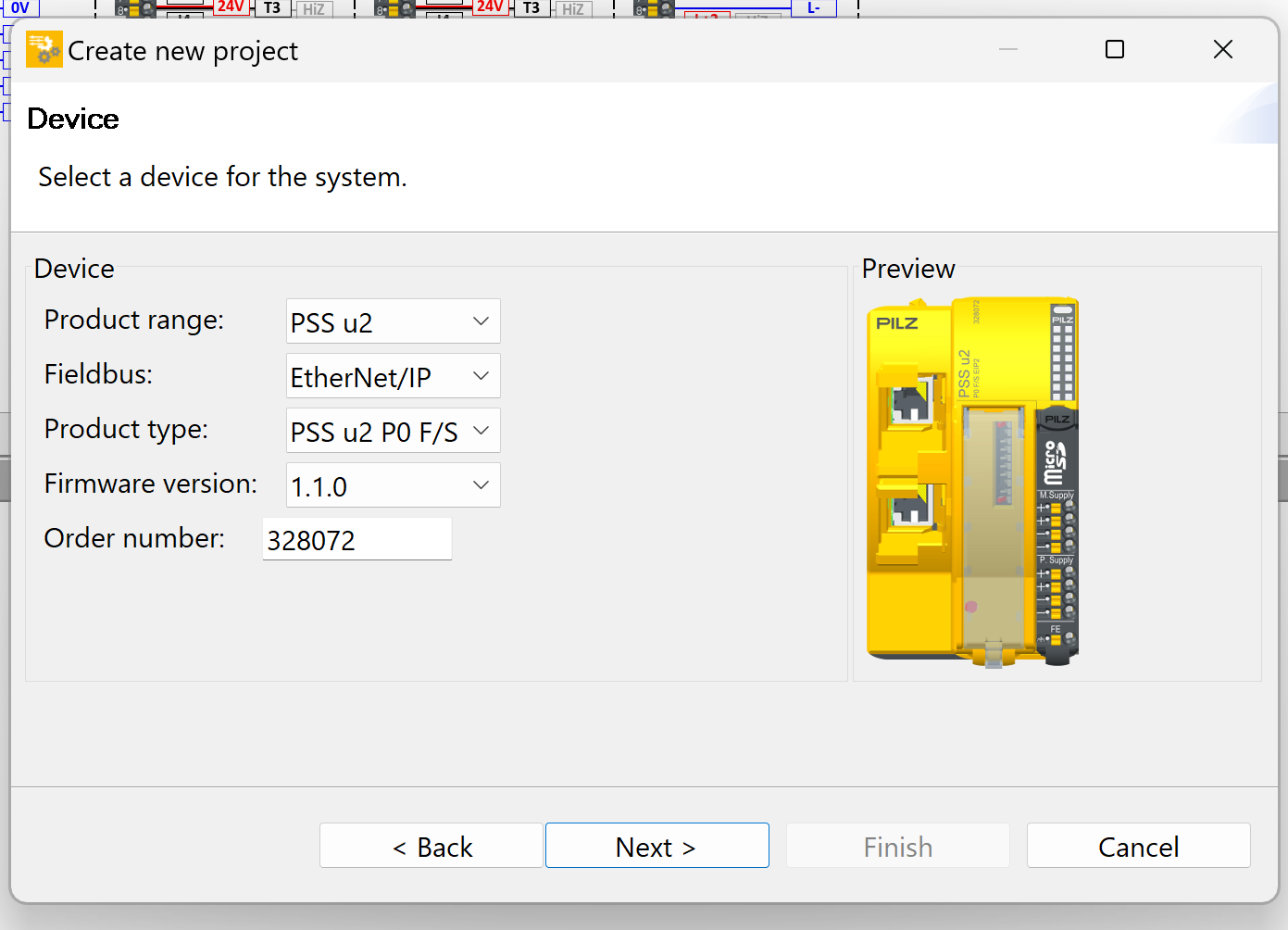
Next, the screen changes to the Device settings screen.
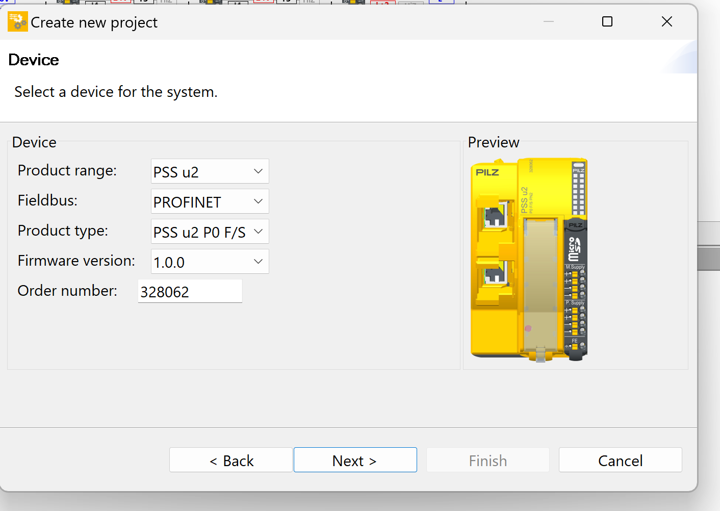
In this case, PSS u2 EIP2 will be used, so configure it according to the actual device as follows.
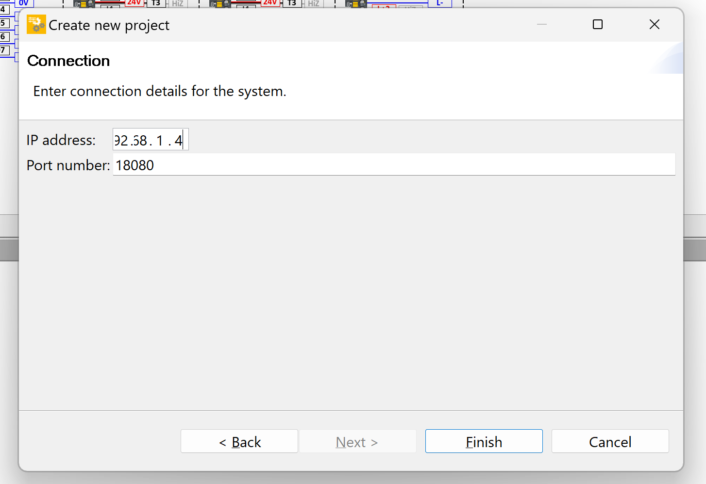
Next, enter the device name.
Match the IP address of the device and proceed with Next>.
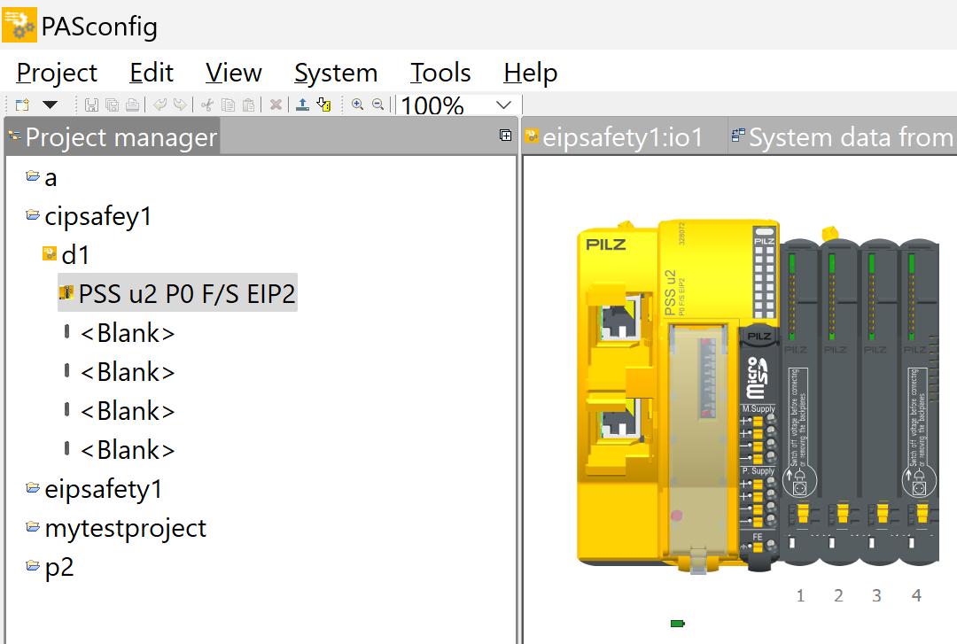
Done!Project created.
Check Connection
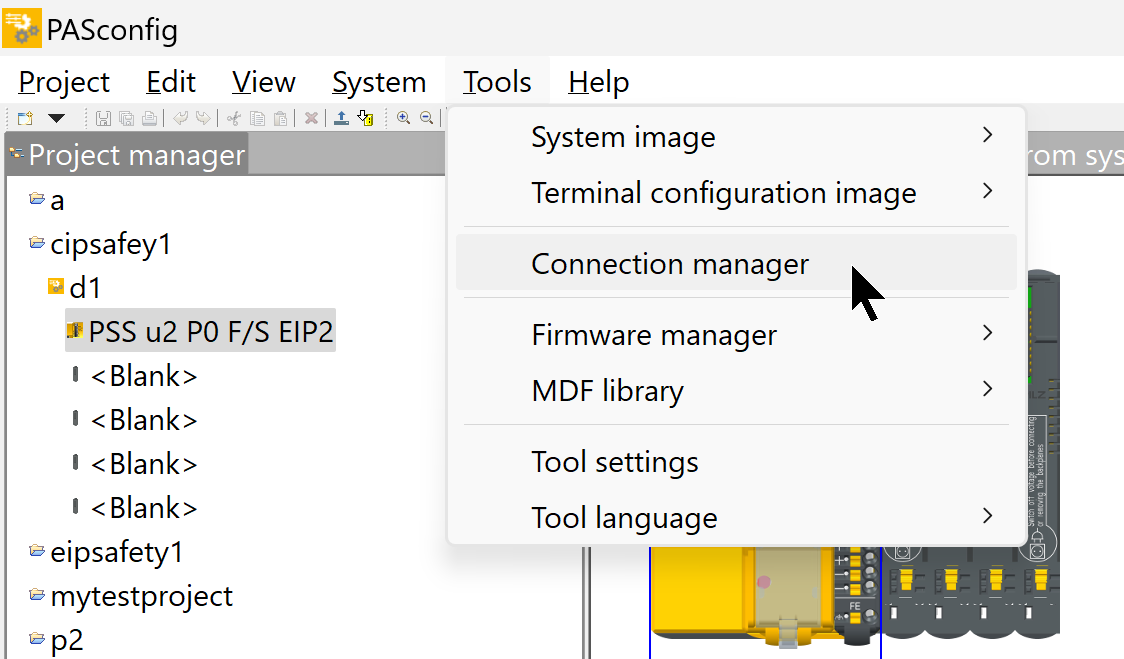
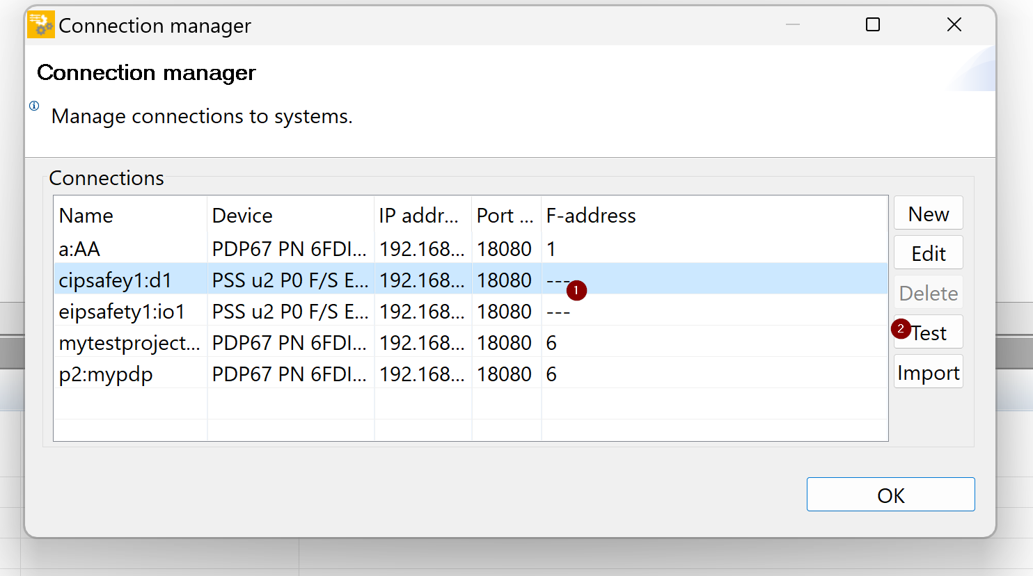
Now open Tools>Connection Manager to check the connection between the PC and the PSS u2 P0 F/S EIP2.
Select the device you have just created and go to >Test.
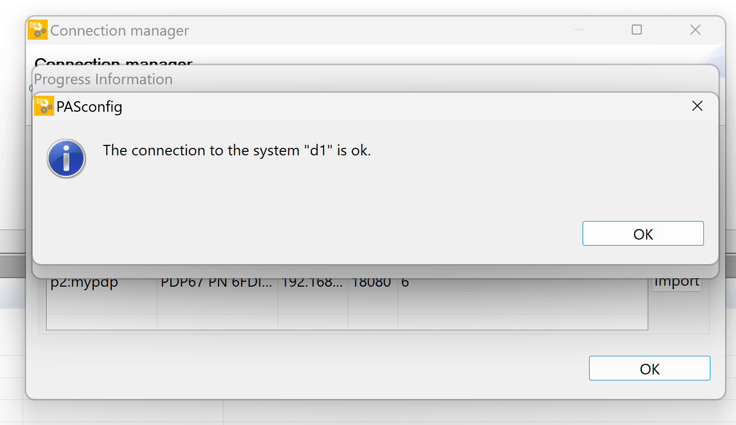
Done!
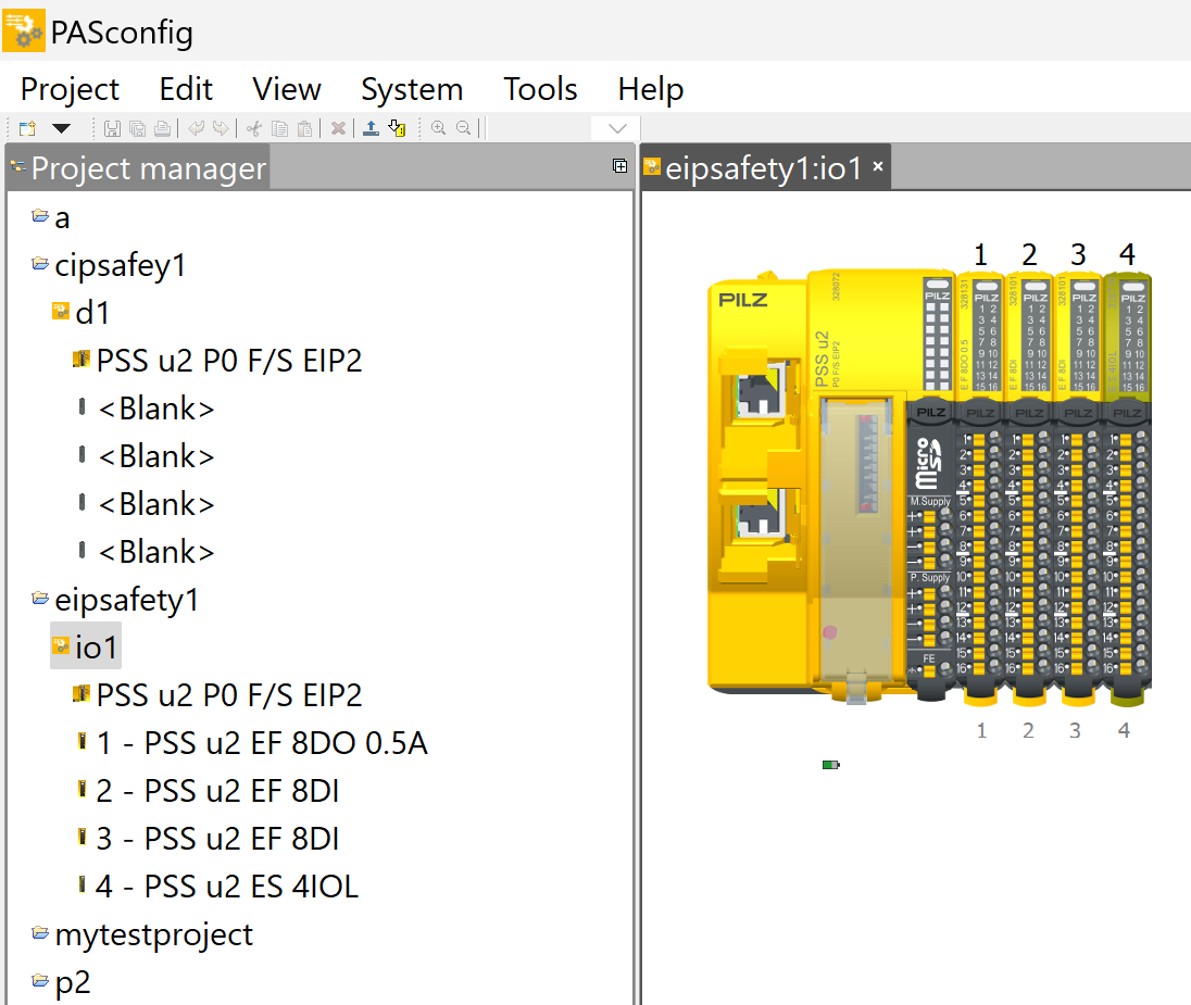
Configuration Slot
Next, build a project to match the Slot installed on the actual device.
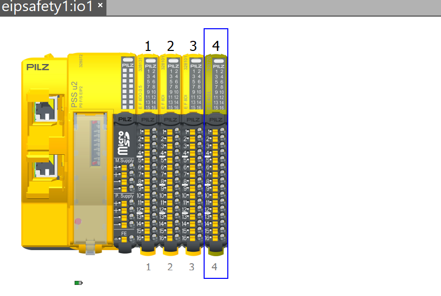
Configure IO-Link Slot Size
Click on IO-Link Master to configure the Pilz IO-Link Master module to be used in this case.
Set the size of each Channel’s IO LINK Channel in System Overview>Module>Overall process image size. This time, set it to 32 ByteIN/OUT data exchange, which means that 32 Bytes of input/output data will also be exchanged on each Channel’s IO Link device.
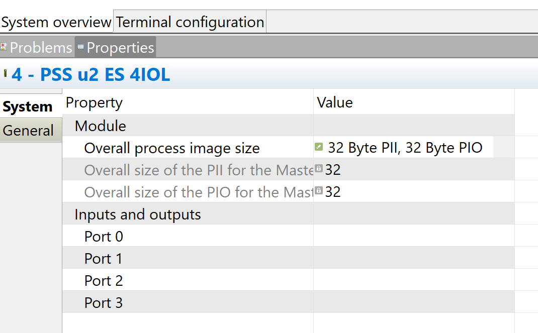
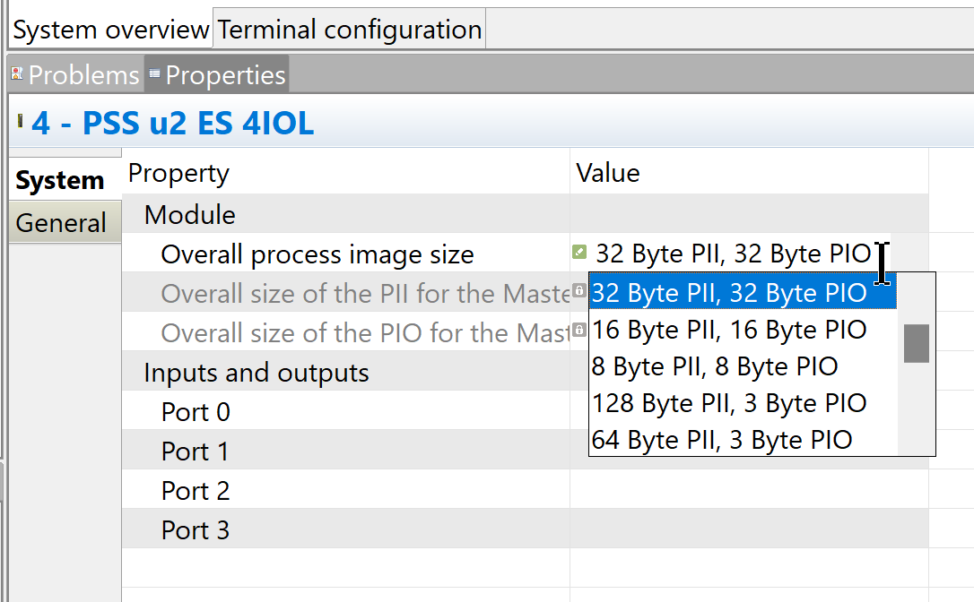
The data size can be changed from the Drop-List in the Overall process image size section.
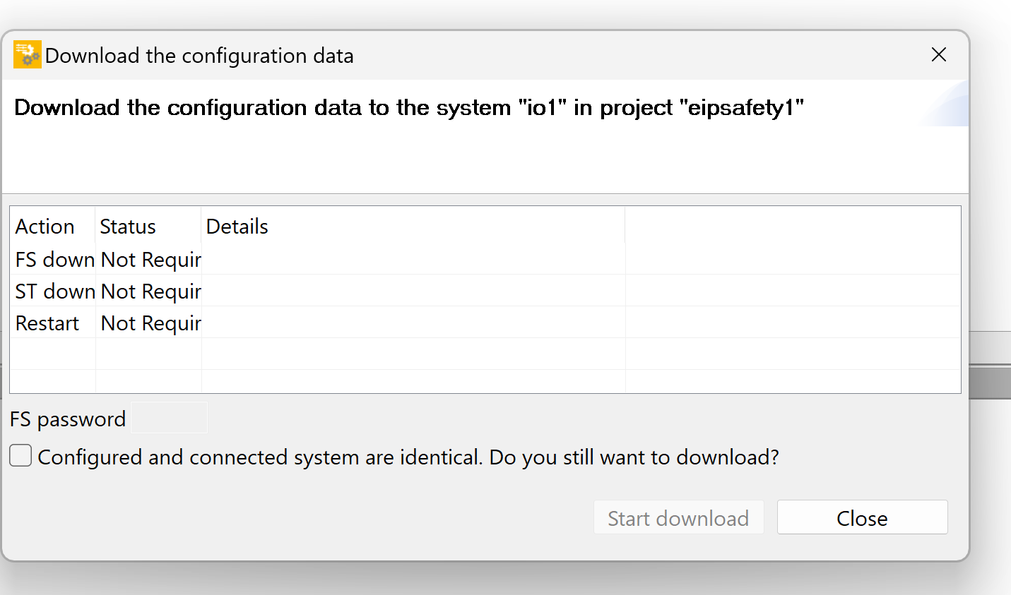
Download Configuration
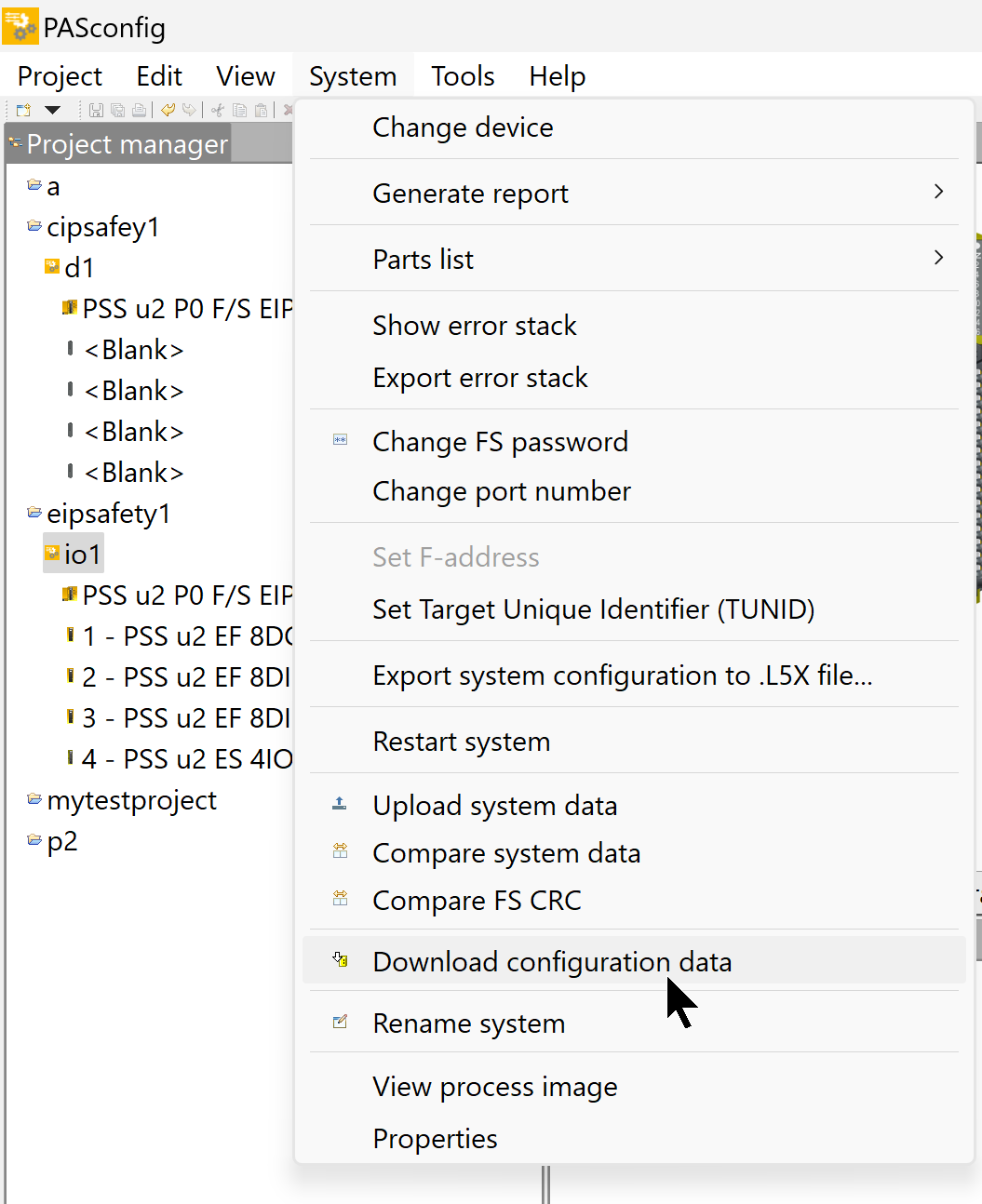
Click System>Download Configuration data and use Download Configuration Data to download the project to the module.
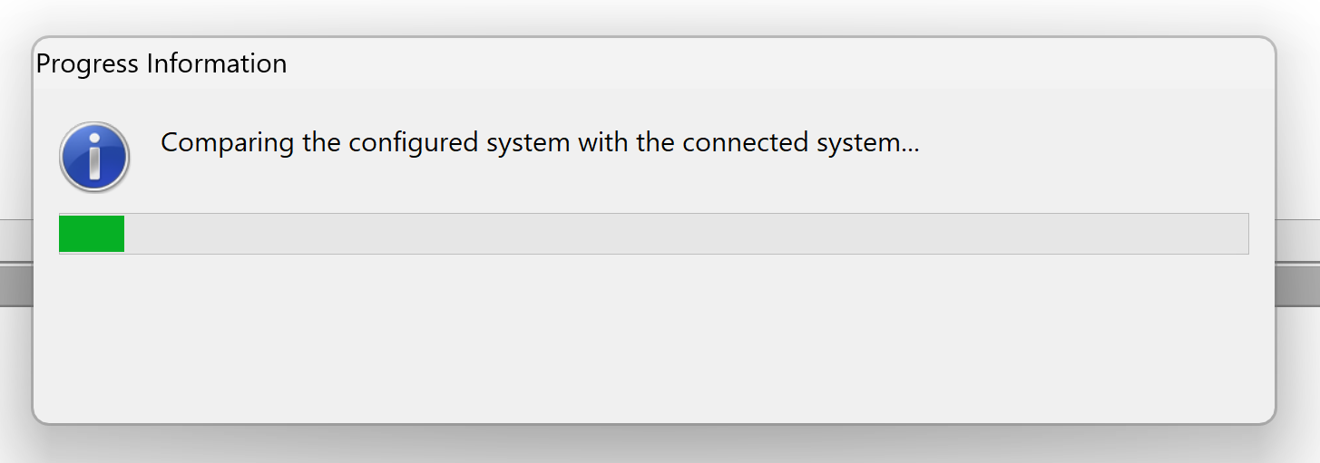
Just a second..
The Password entry screen will appear and you should enter your FS Password and download it.
Omron Side
The next step is to build the Omron NX1 side.
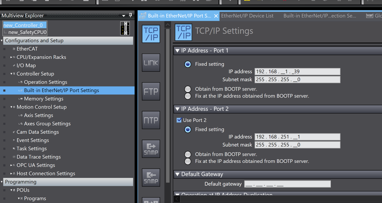
Configure IP
Configure the IP settings of the NX1 CPU: configure each Ethernet Port in Configuration and Setup>Controller Setup>Built in Ethernet/IP Port Settings.
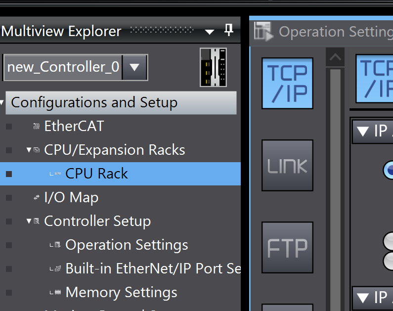
Add SL5700
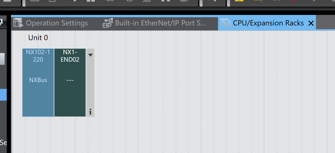
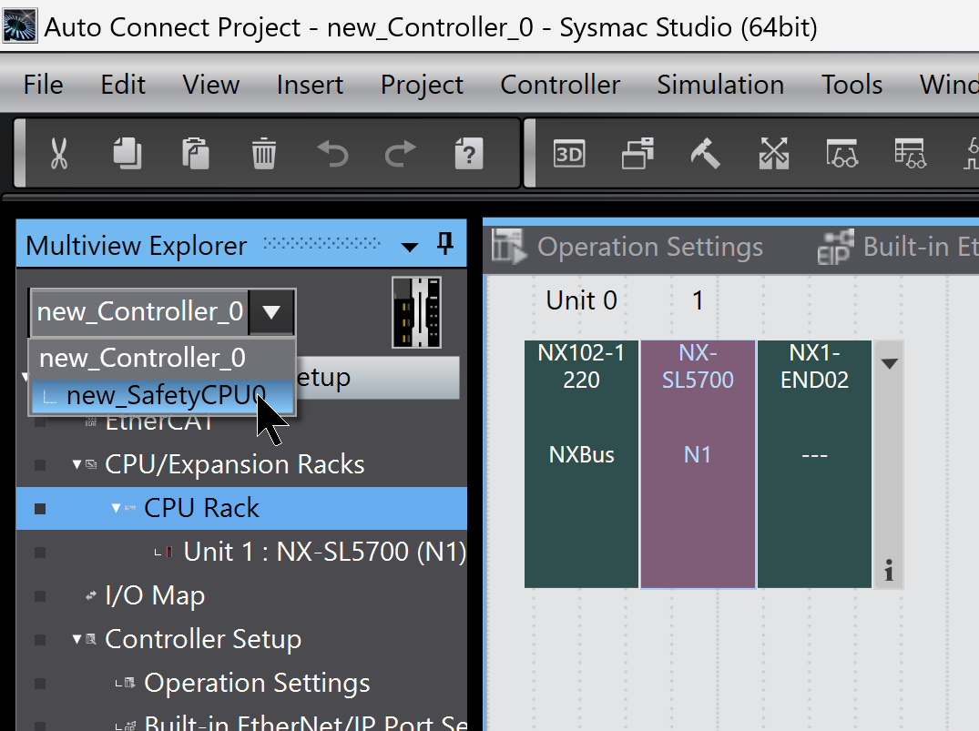
To add an OMRON Safety CPU Device, click CPU/Expansion Racks>CPU Rack.
The Configuration screen is displayed.
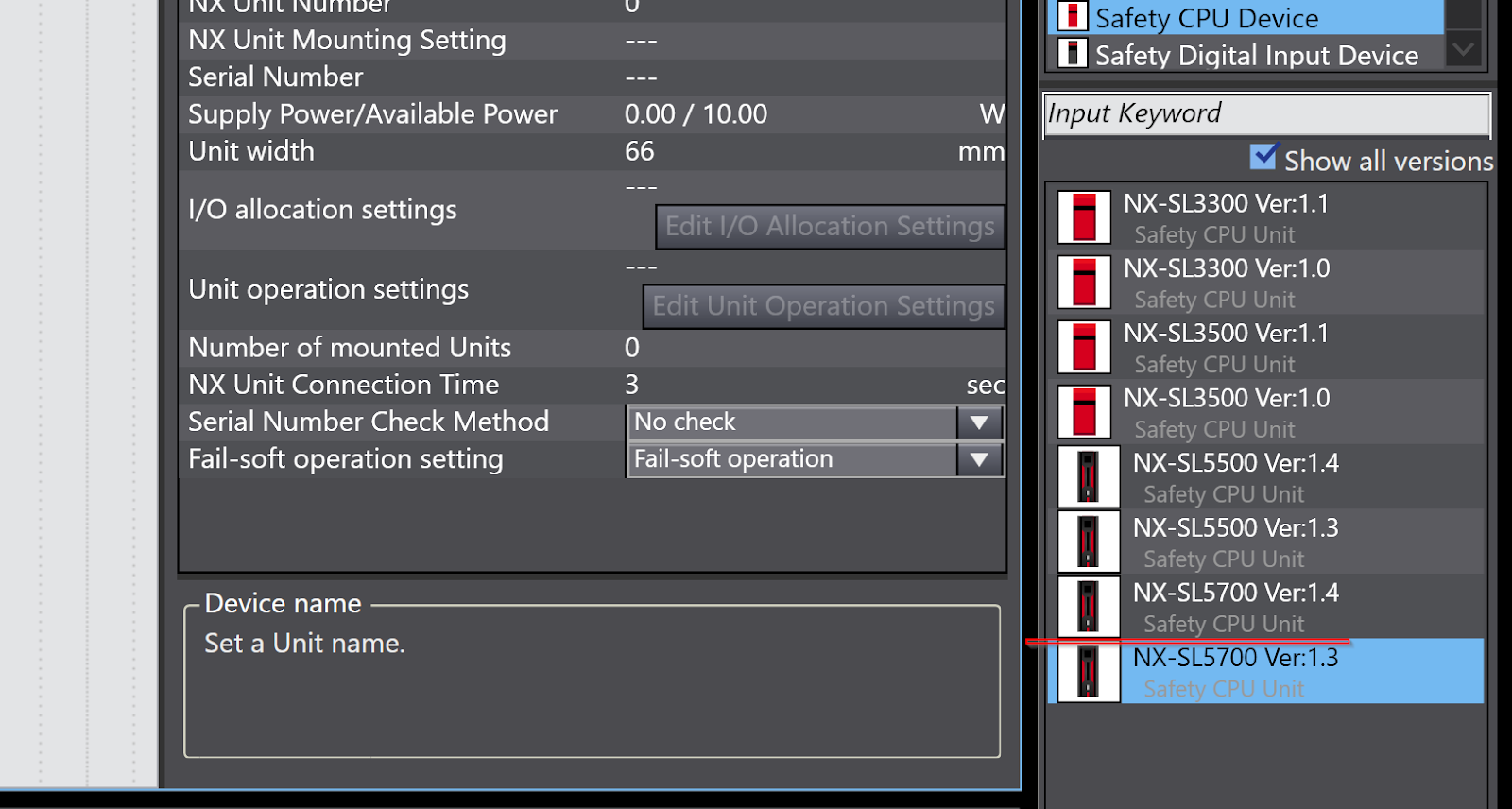
Select Toolbox>Safety CPU Device and tick the “Show all versions” checkbox. The Safety CPU Device at hand is not always the latest version, and Omron’s Safety CPU Device Firmware needs to match the actual device and project.
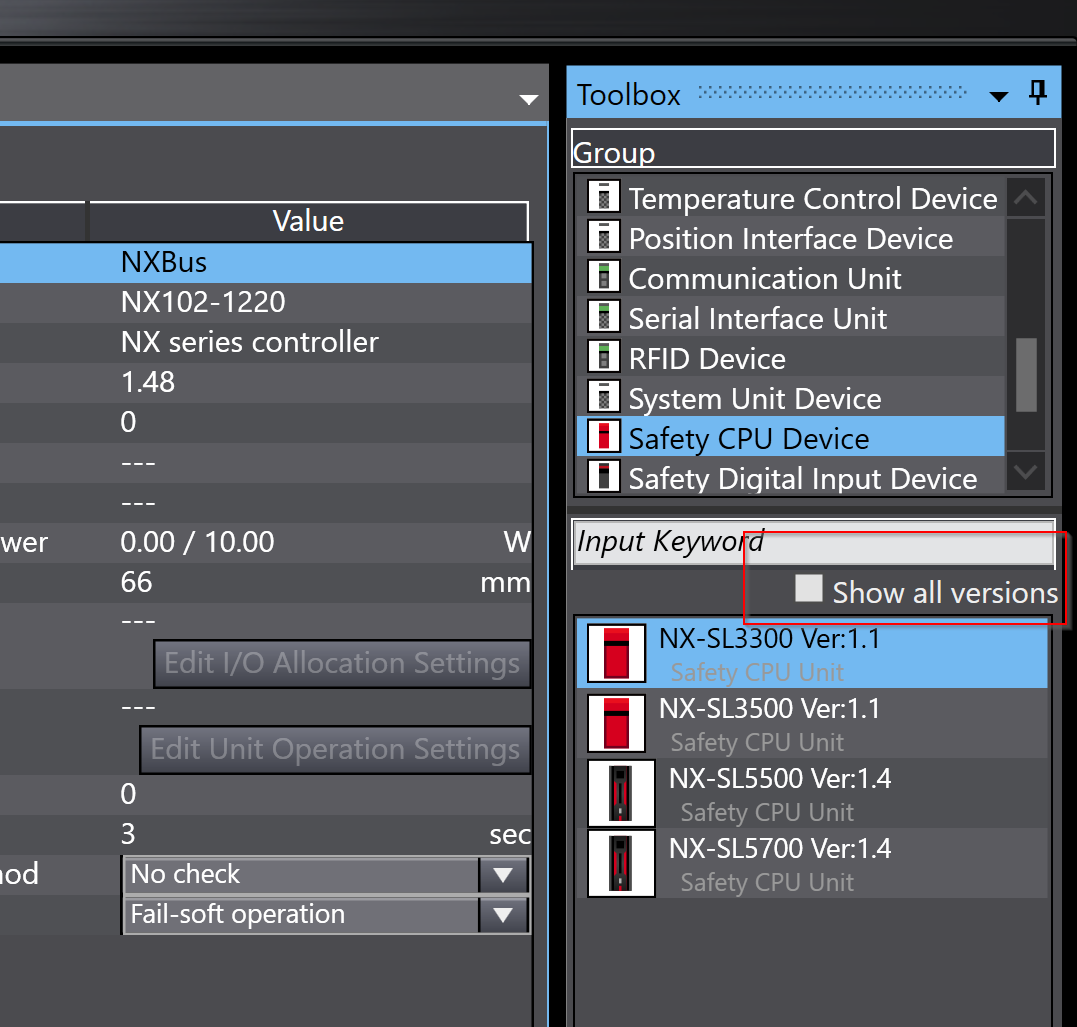
The Safety CPU Device used in this case is the NX-SL5700 Ver 1.3.
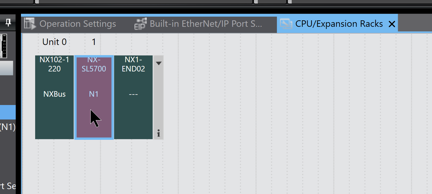
Right-click NX-SL5700 Ver 1.3>Insert.
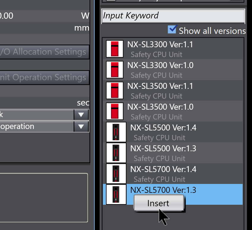
Done!
Configure CIP Safety Connection
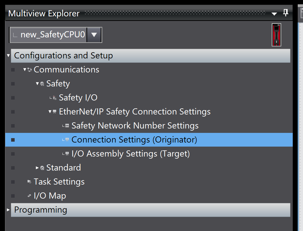
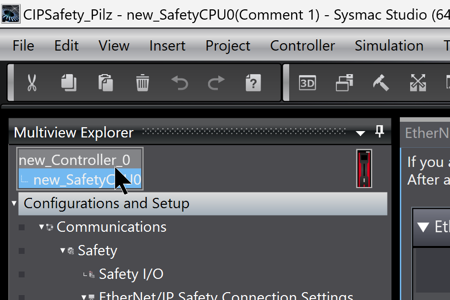
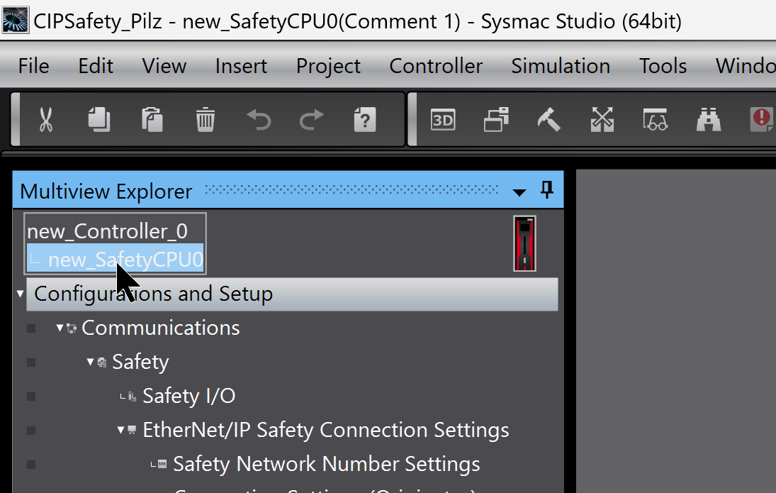
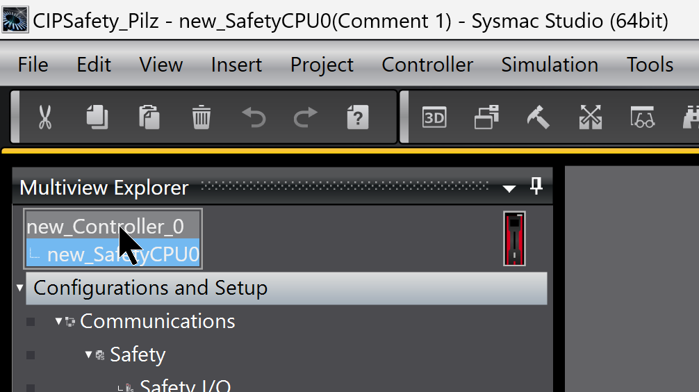
Now open the Safety CPU Device you have just defined from the Drop-List in order to configure CIP Safety communication.
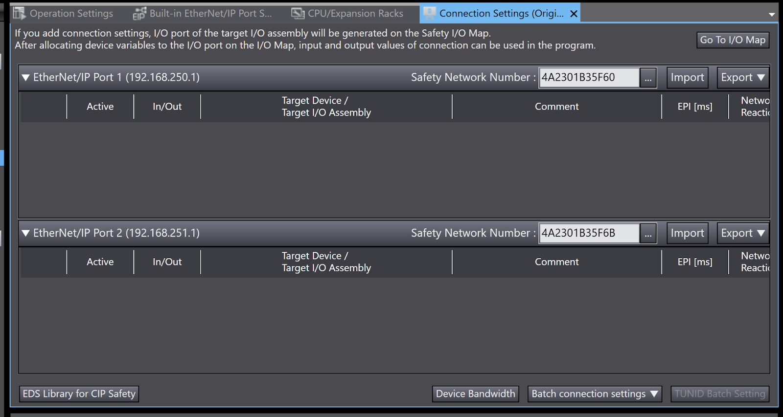
Click Communications>Safety>Ethernet/IP Safety Connection Settings>Connection Setting (Originator).
This is the CIP Safety configuration screen in Sysmac Studio.
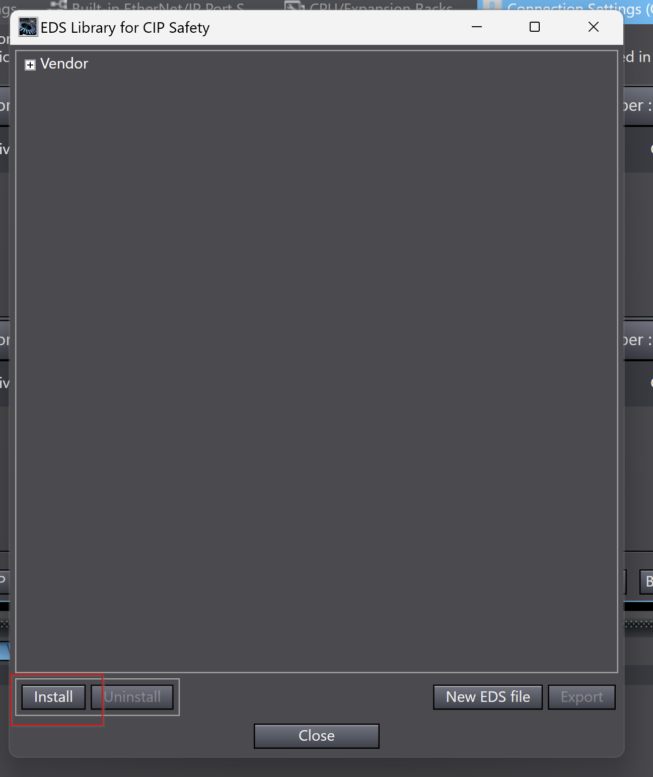
Install EDS File
Right-click on an empty EtherNet/IP Port location>EDS Library for CIP Safety and install the EDS File for PSS u2 P0 F/S EIP2.
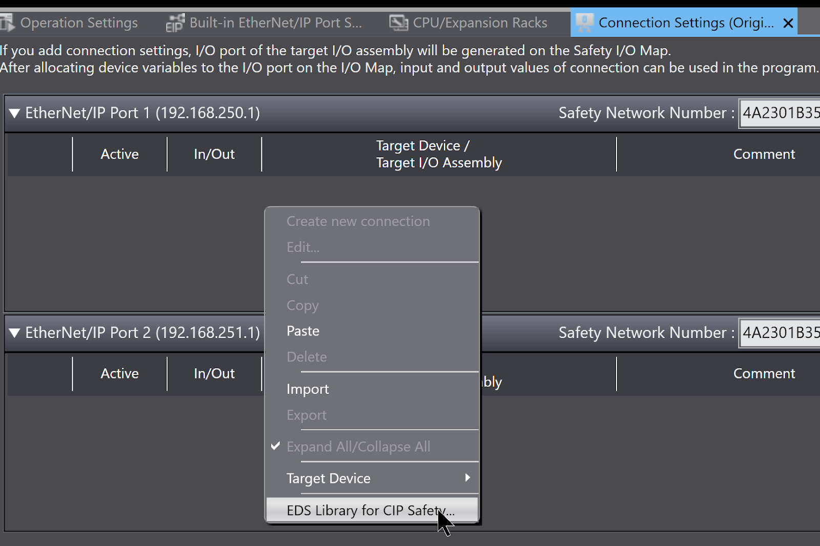
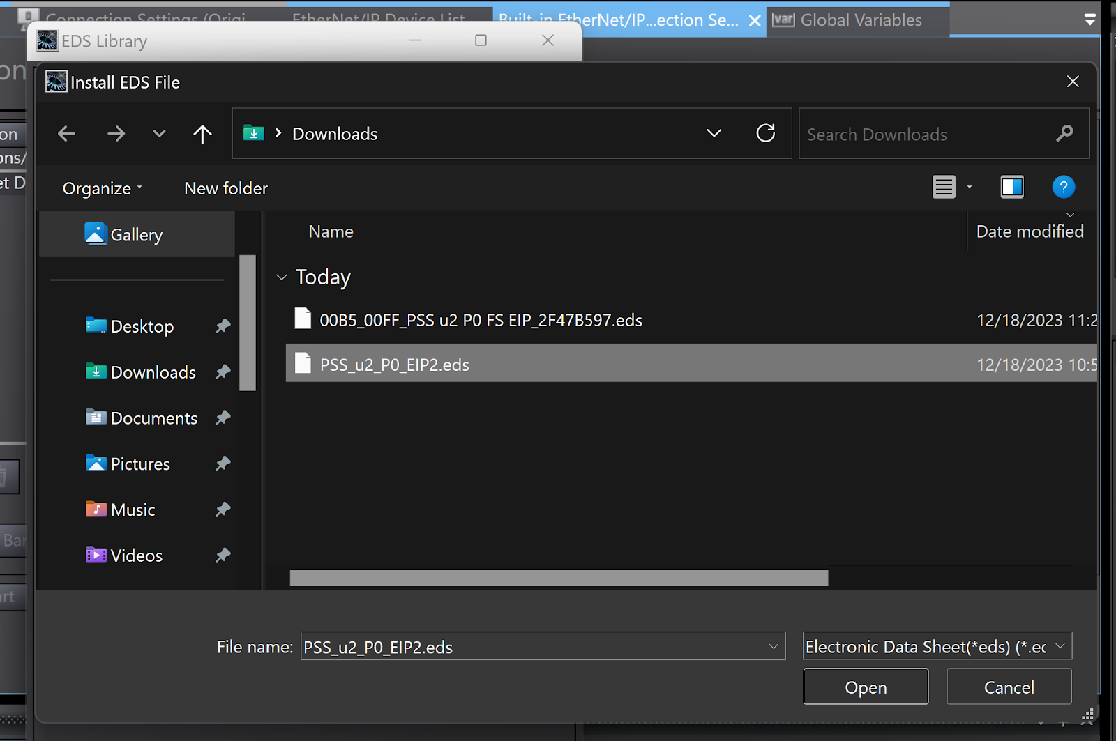
Register the EDS File using the Install button.
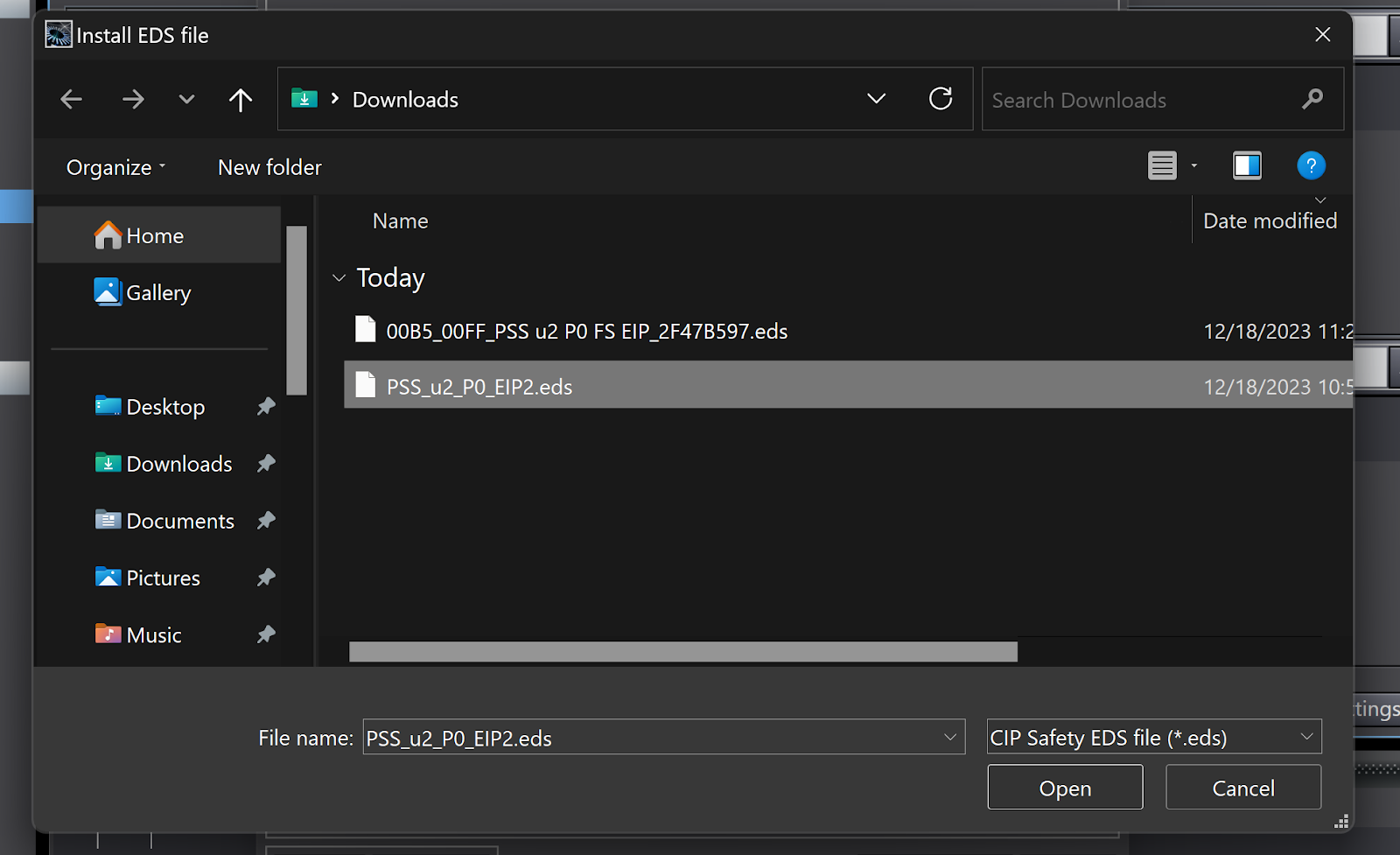
Select the EDS File downloaded from the Pilz website.
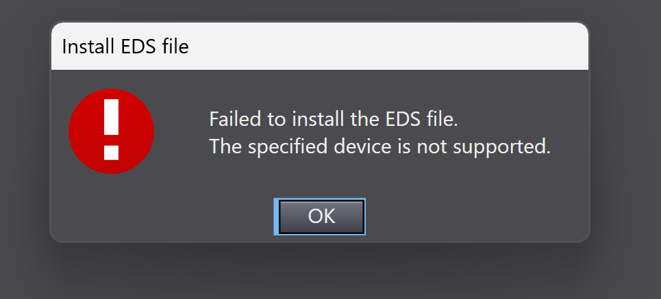
But Sysmac Studio does not support this EDS File.
Create the EDS File
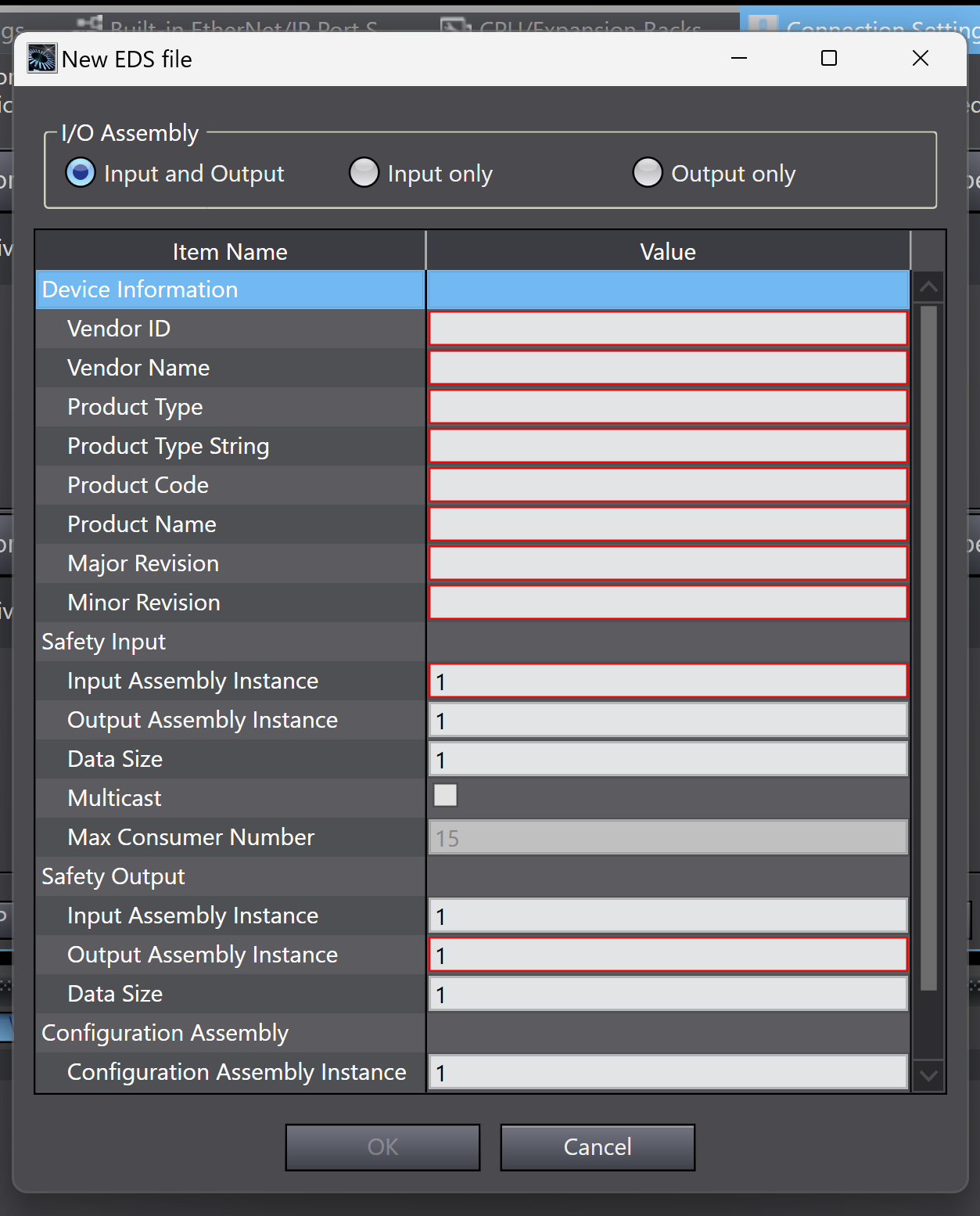
In fact, Sysmac Studio also provides an EDS File creation tool called “New EDS File” for EDS Files that cannot be imported.
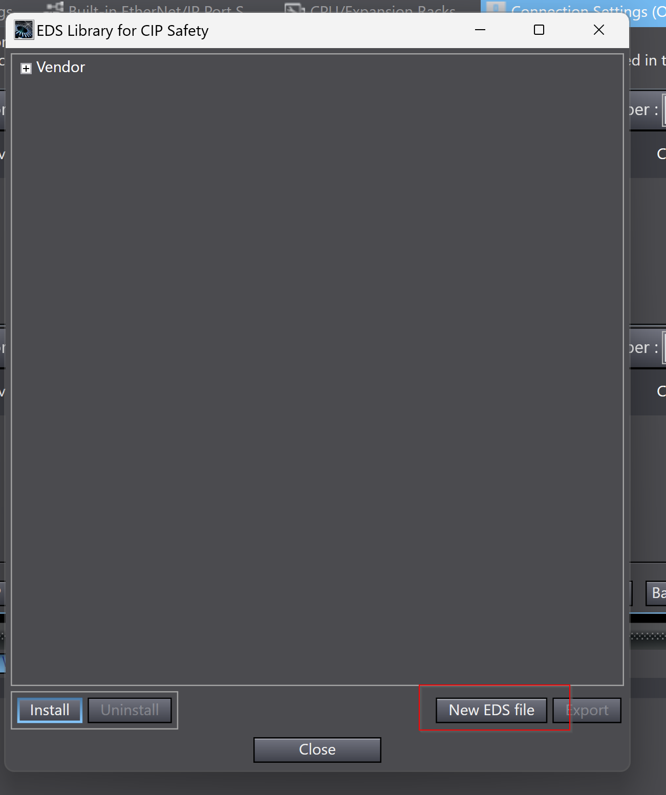
This is the Safety EDS File creation screen.
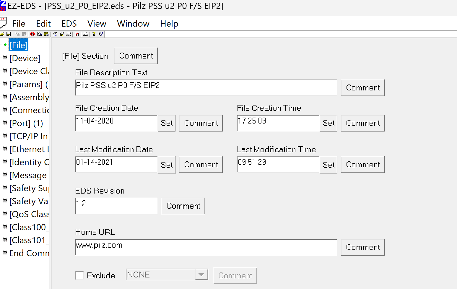
USE E-Zeds Tools
To create an EDS File in OMRON’s Sysmac Studio, it is more convenient to use a tool called EZ-EDS.
Download from this Link, launch the tool>Open the Pilz EDS File.
https://www.odva.org/subscriptions-services/additional-tools/ez-eds-download/

The EDS Type can be either Etherent/IP EDS or Generic EDS.
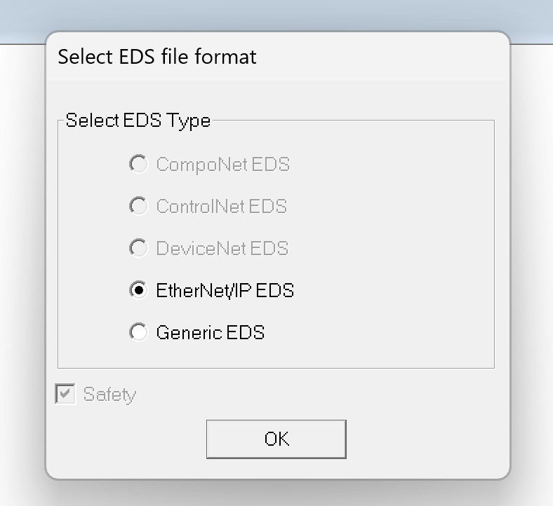
Proceed with Continue.
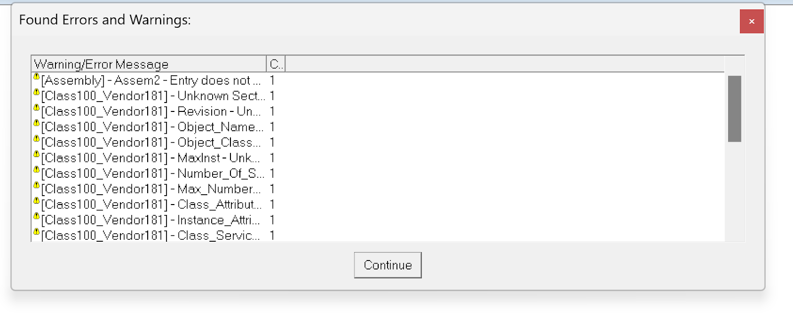
Done!
Vendor ID
The Vendor ID corresponds to Device>Vendor ID in the EZ-EDS tool.
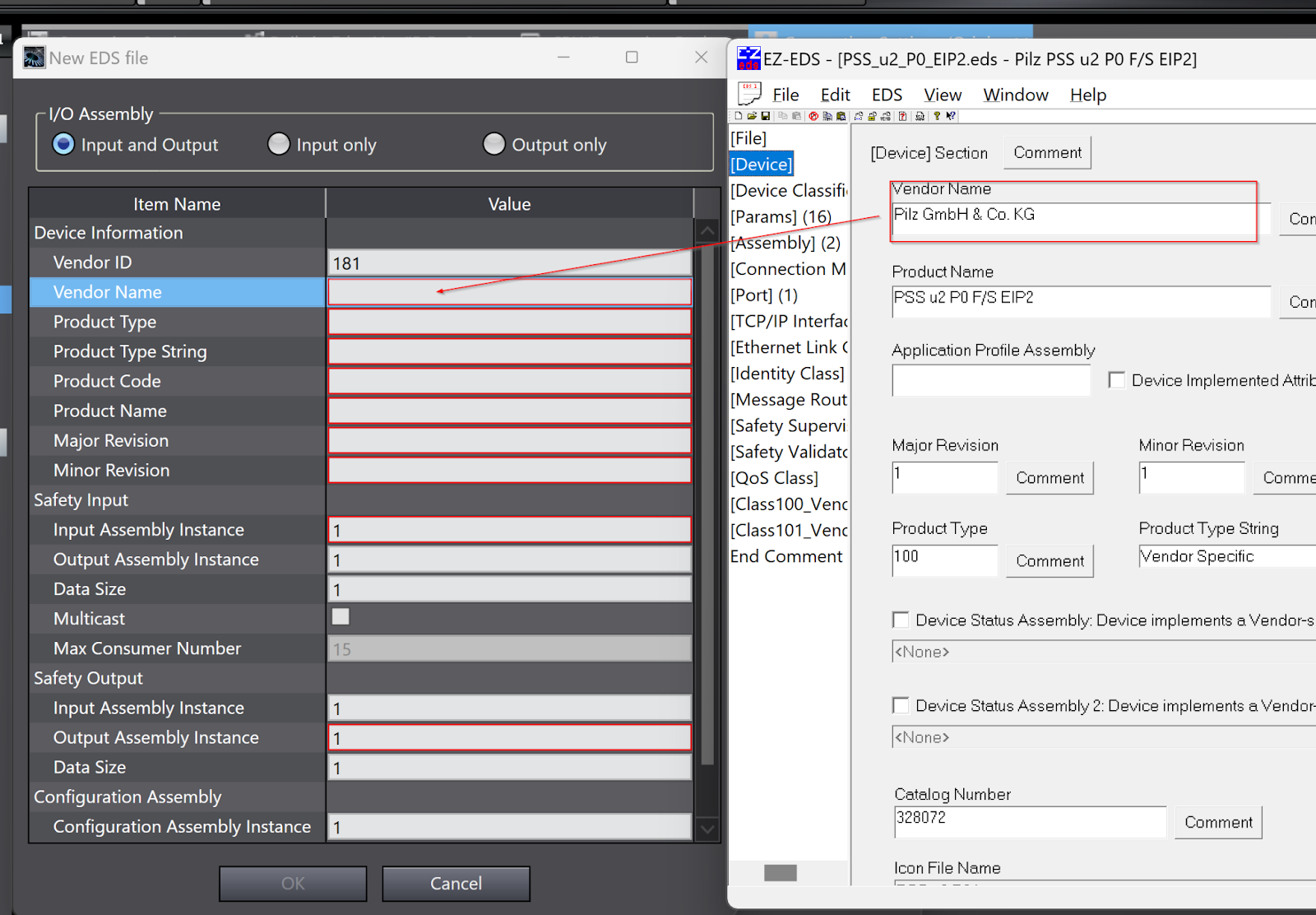
Vendor Name
Vendor Name corresponds to Device>Vendor Name in the EZ-EDS tool.
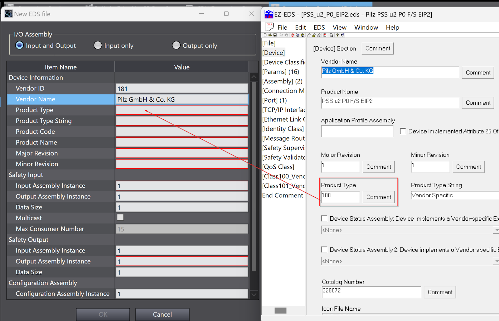
Product Type
Product Type corresponds to Device>Product Type in the EZ-EDS tool.
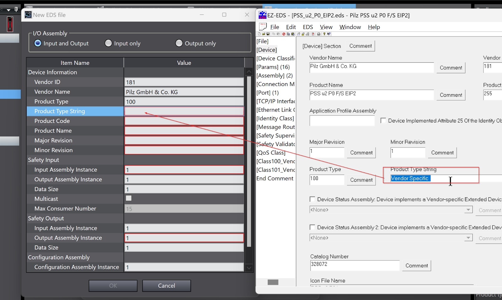
Product Type String
The Product Type String corresponds to Device>Product Type String in the EZ-EDS tool.
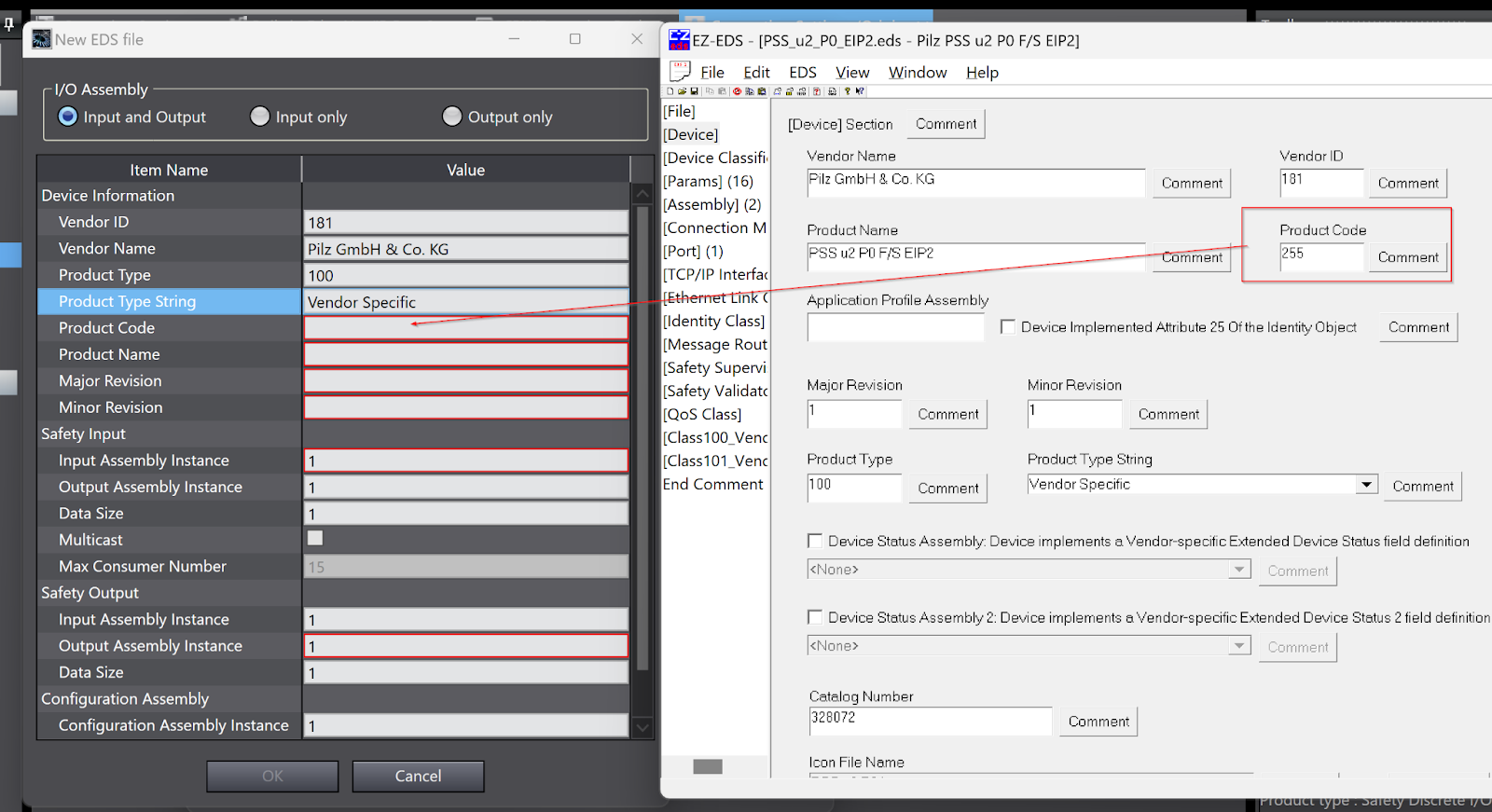
Product Code
The Product Code corresponds to Device>Product Code in the EZ-EDS tool.
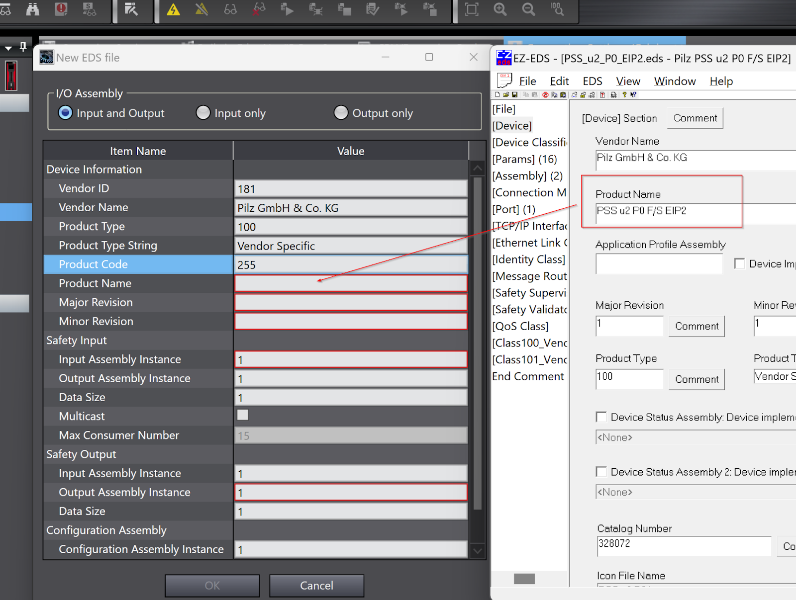
Product Name
Product Name corresponds to Device>Product Name in the EZ-EDS tool.
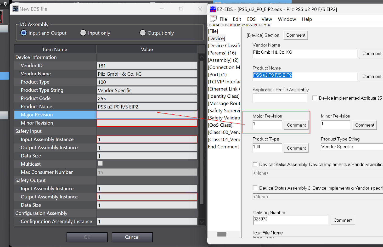
Magjor Revision
Magjor Revision corresponds to Device>Major Devision in the EZ-EDS tool.
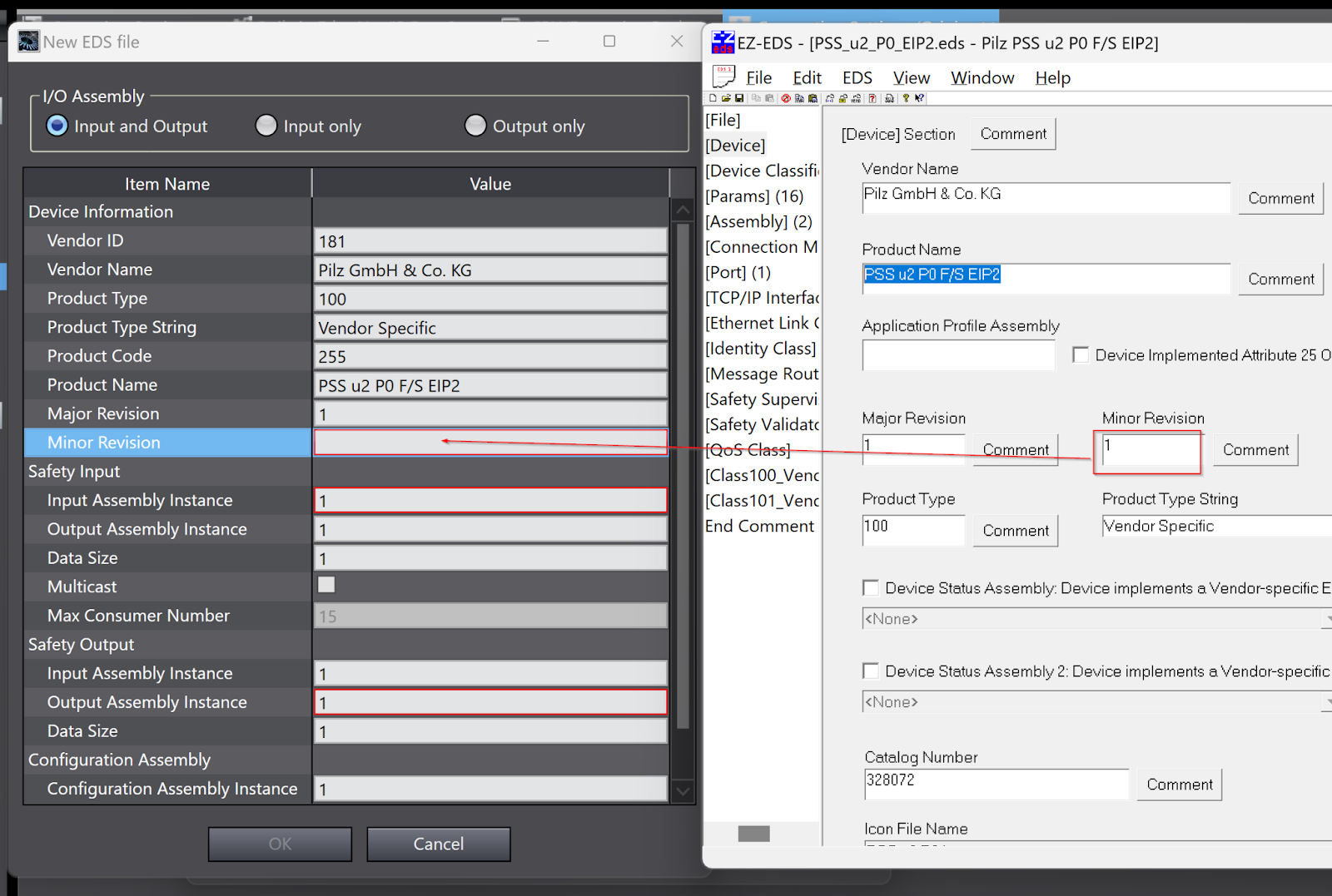
Minor Revision
Minor Revision corresponds to Device>Minor Revision in the EZ-EDS tool.
Safety Input
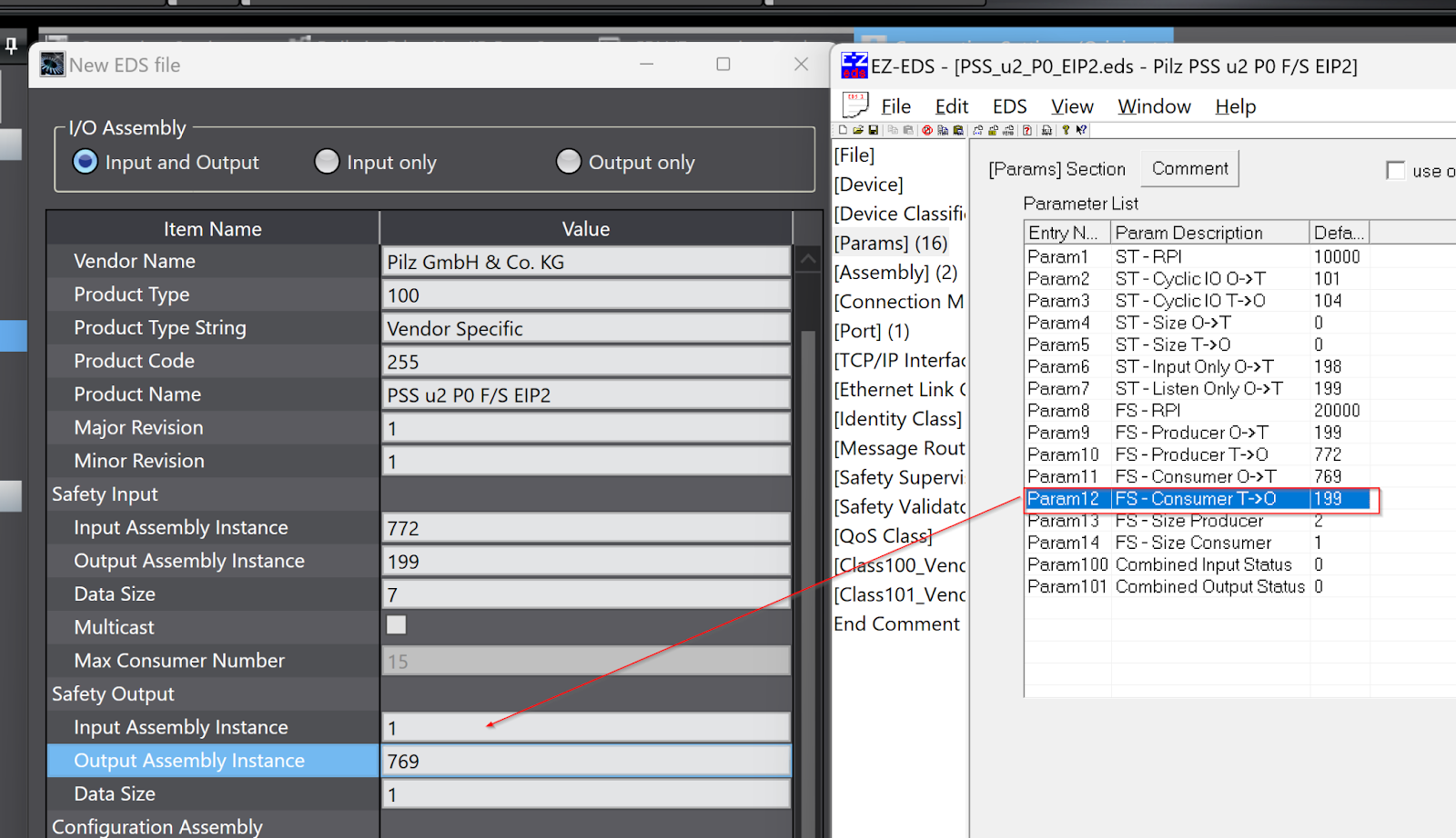
Now open the Params Field to configure the Safety input part of the EDS File.
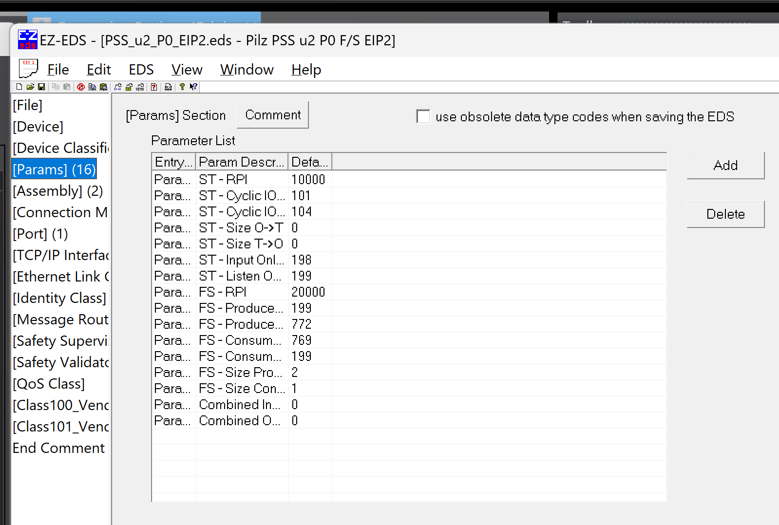
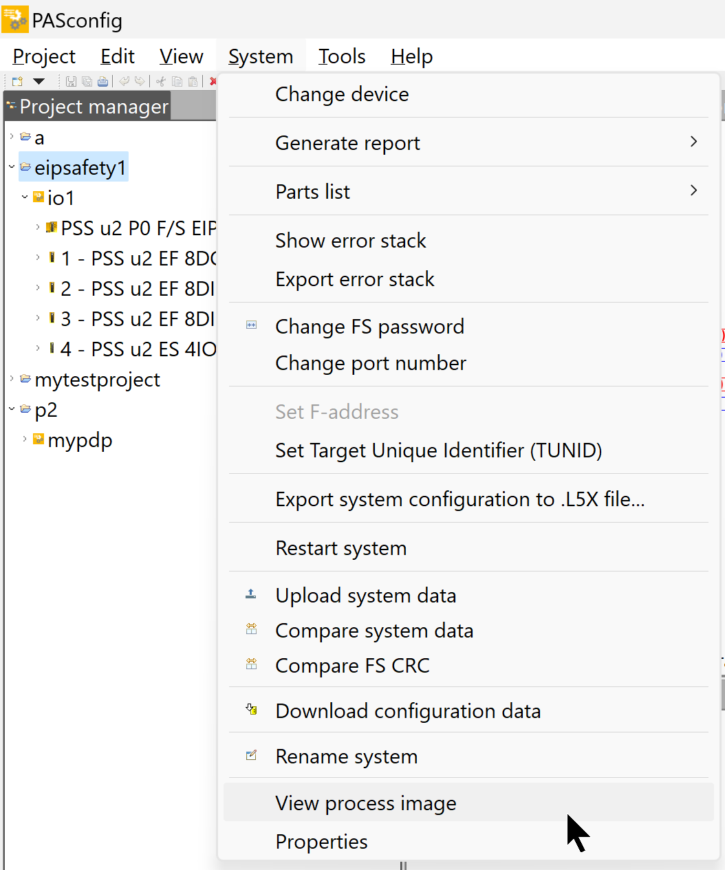
To create an EDS File, you need to know the number of Bytes of input and output data, click PASconfig>System>View process image in Pilz.
For use in this article, the CIP Safety module itself and the input data together use 7 Bytes and the Input Assembly number is 772.
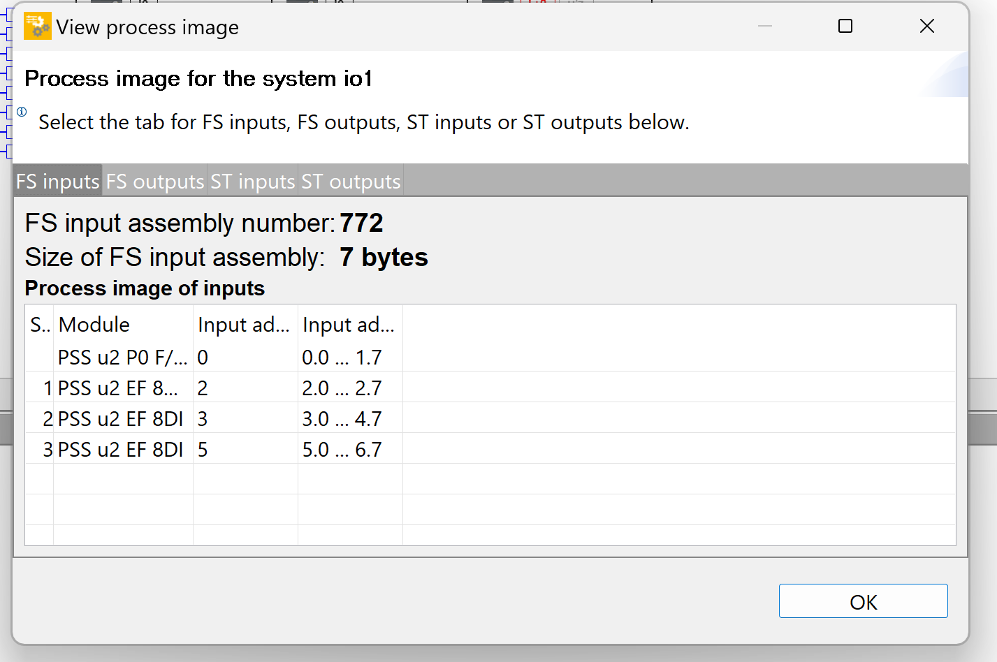
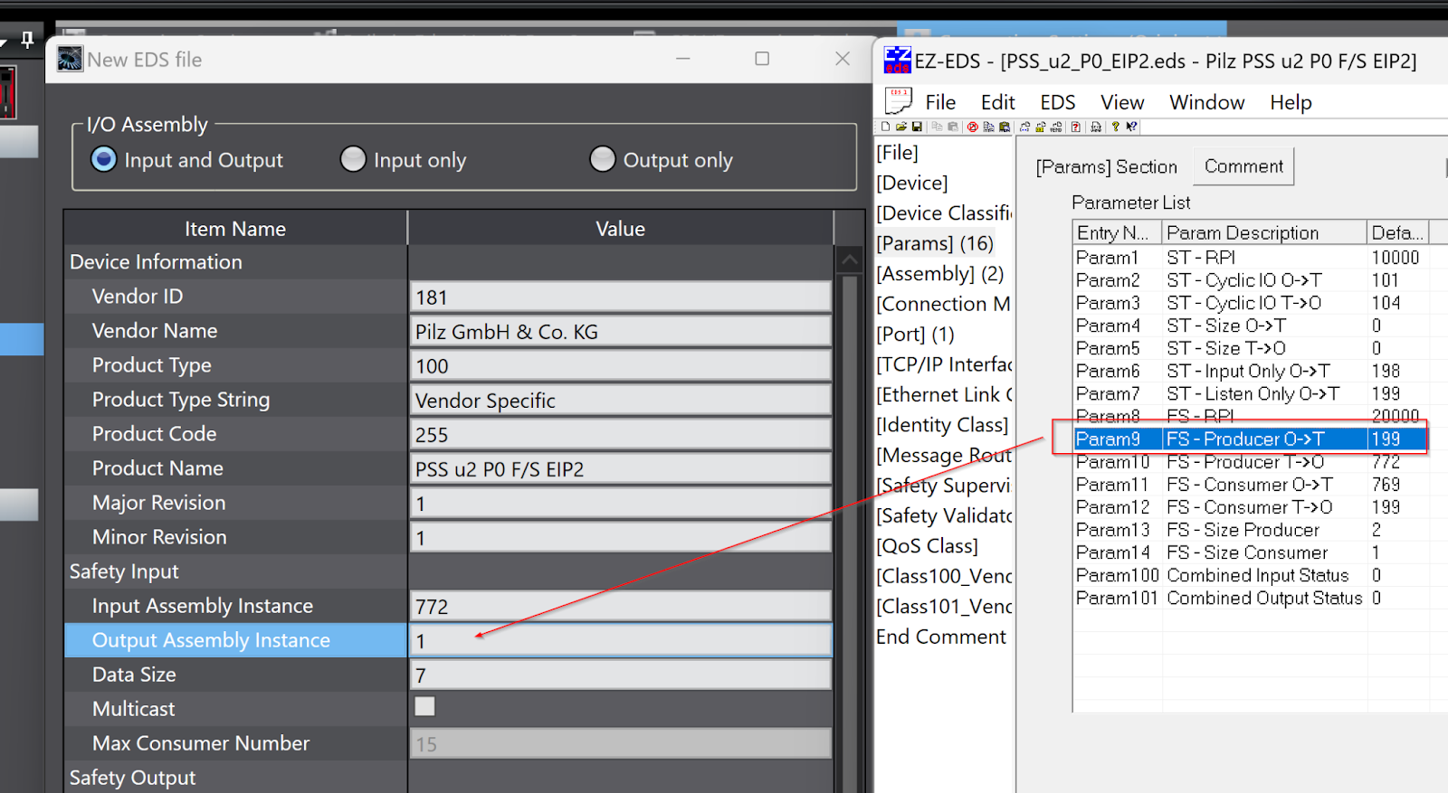
The Input Assembly for Safety Input is 772, the Output Assembly Instance is 199 and the Data Size is 7 Bytes.
Safety Output
For use in this article, the CIP Safety module itself and the output data together use 1 Bytes and the Output Assembly number is 769.
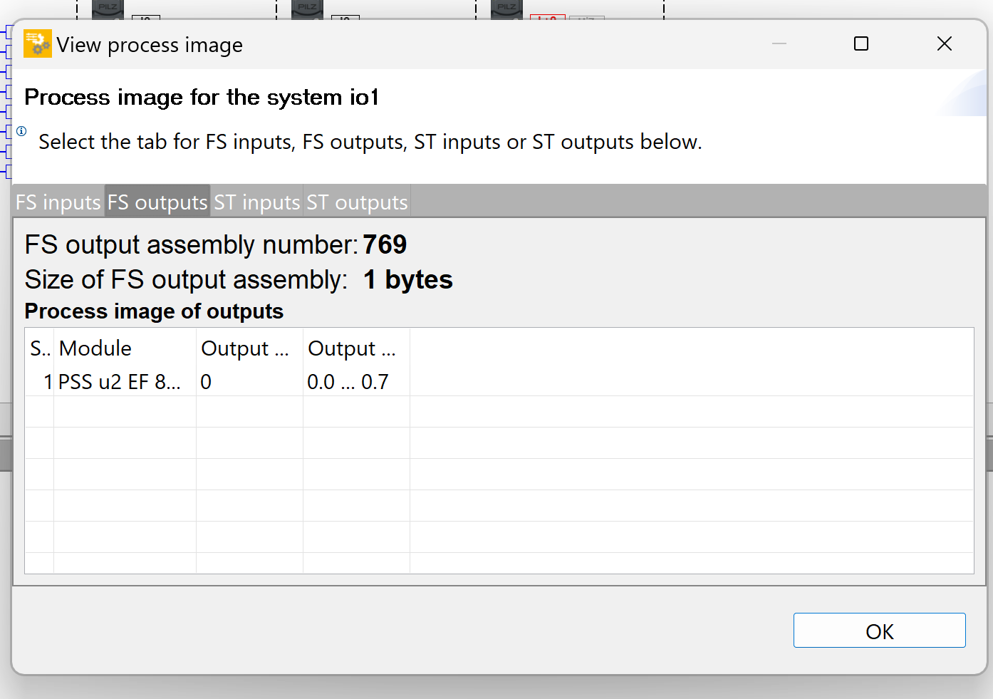
The Input Assembly for Safety Output is 769, the Input Assembly Instance is 199 and the Data Size is 1 Bytes.
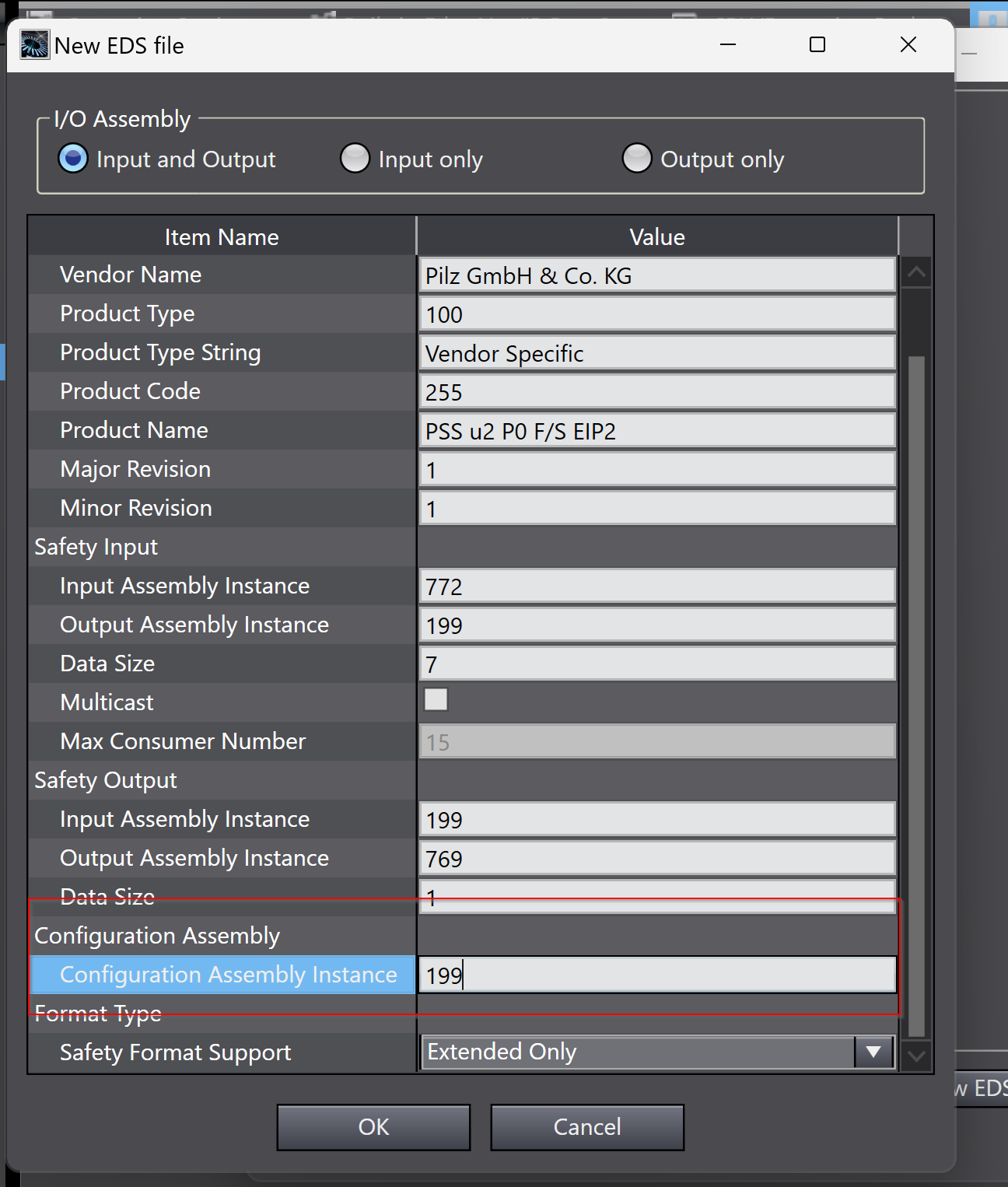
Configuration Assembly
The Configuration Assembly number is 199.
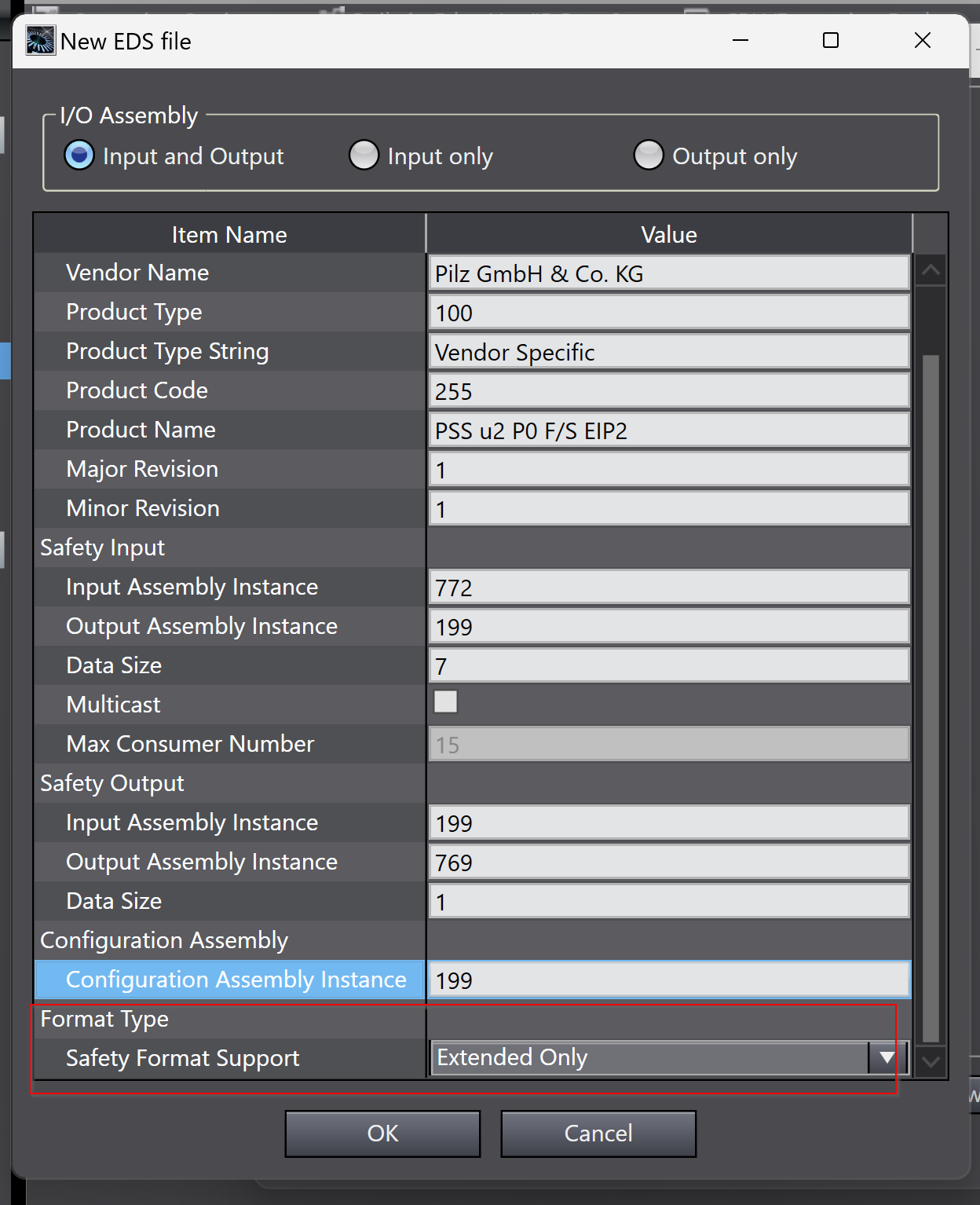
Format Type
This time the SL5700 and the NX CPU control the output data of the PILZ CIP Safety module, so set Safety Format Support to Extended Only.
When you have finished creating the data, you are ready to proceed.
Confirm
Recheck that the EDS File to be created from Sysmac Studio is correct and proceed with Ok.
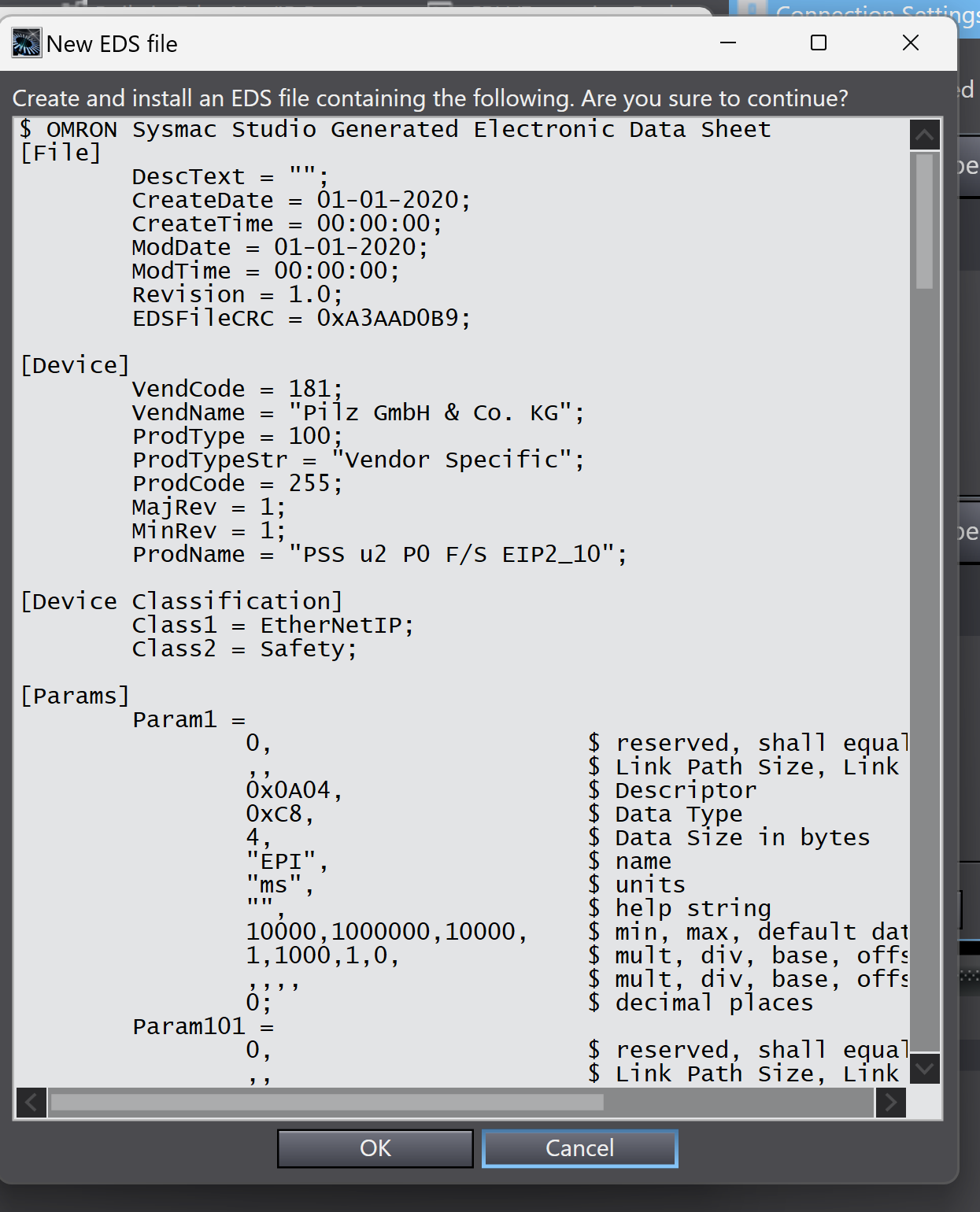
Done!
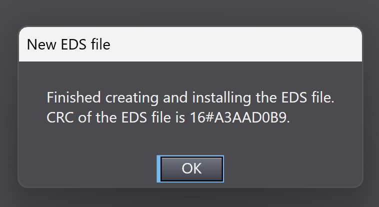
Result
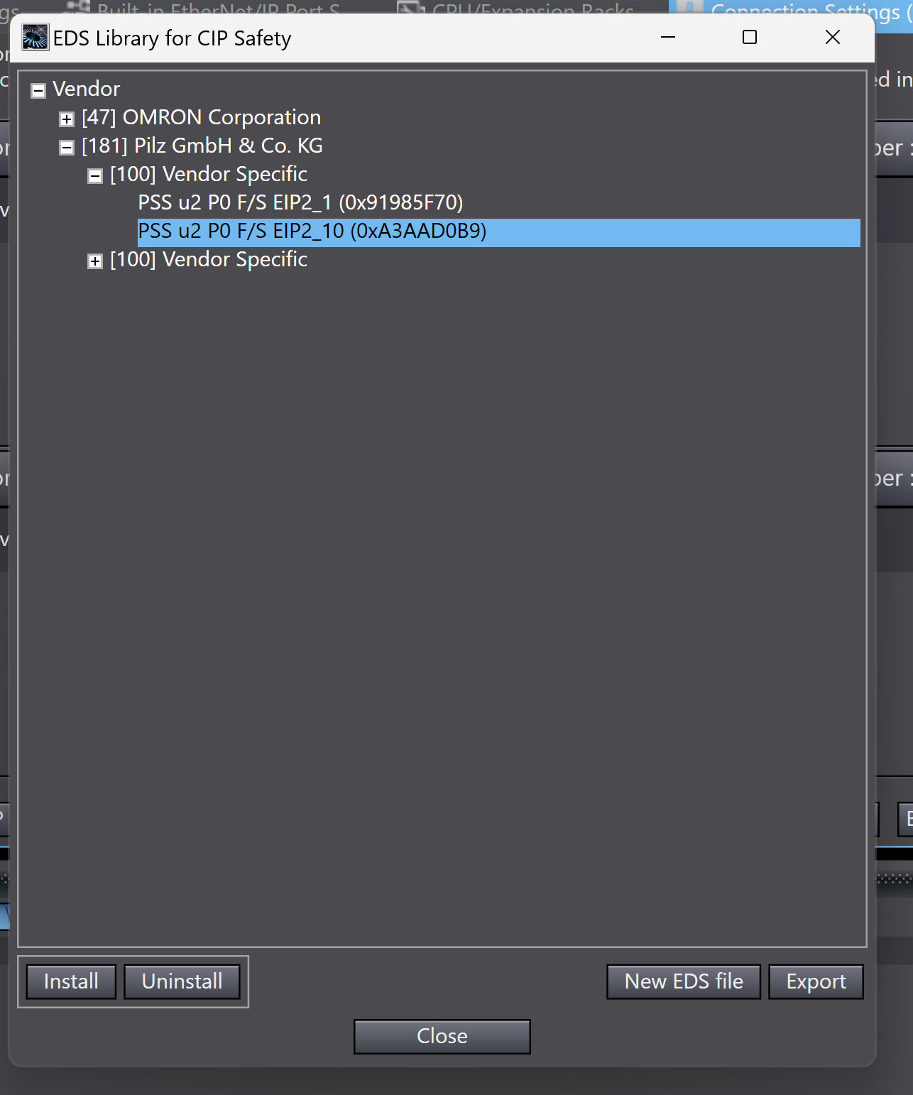
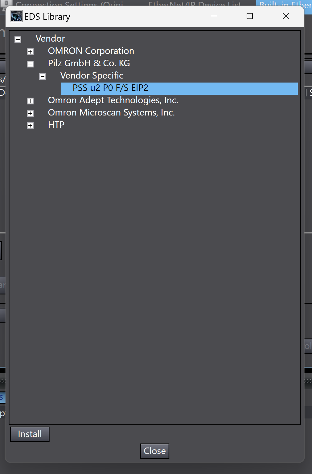
When the EDS Libaray for CIP Safety in Sysmac Studio is opened again, the EDS File created earlier appears.
Insert Devices
Select the Pilz CIP Safety module PSS u2 P0 F/S EIP2 that you have just added > right-click > Insert to add it to the CIP Safety network.
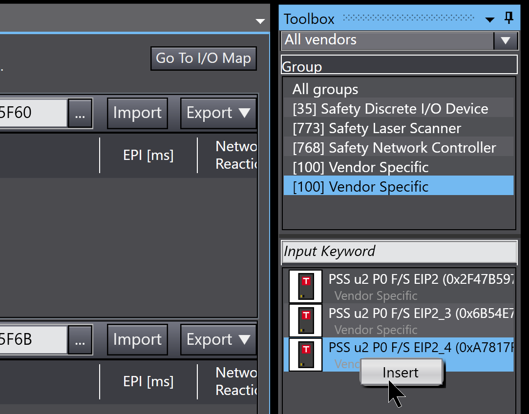
Done!
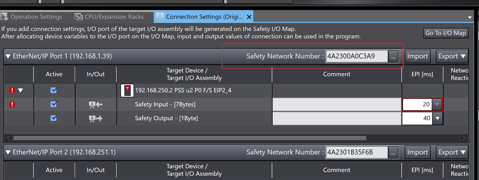
Safety Network Number
To establish a CIP Safety network, the Safety Network Number (TUNID) must be set on the Adapter side; the Safety Network Number of the OMRON SL5700 Port1 can be checked on the Sysmac Studio.
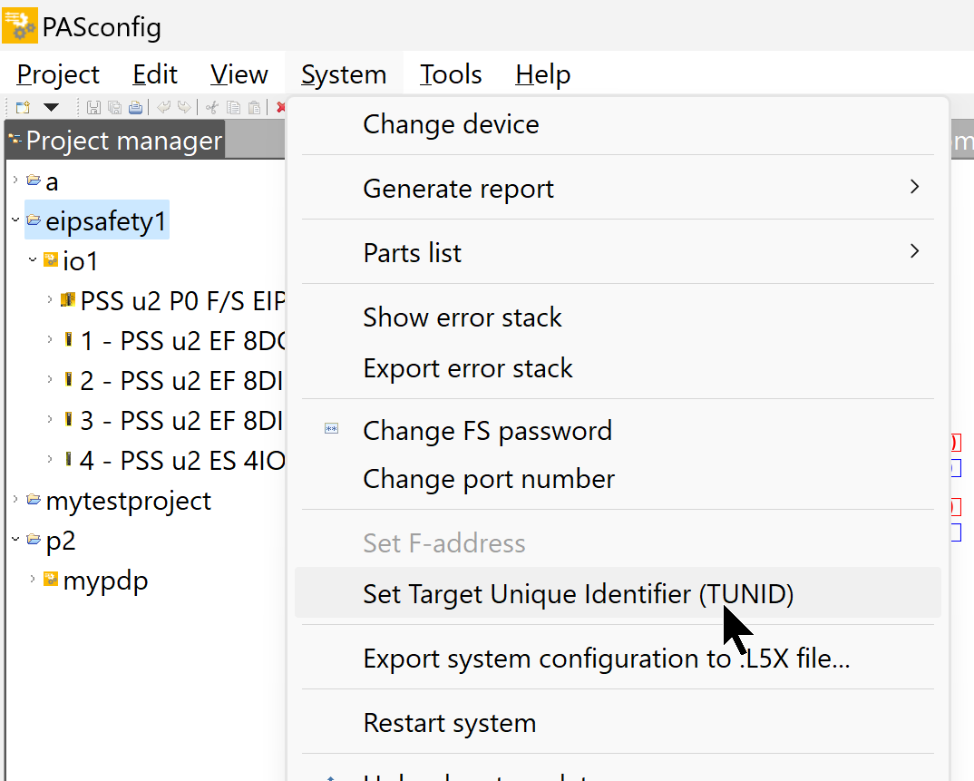
Select the device project with the TUNID you are going to write to and open the >PASconfig tool and click >System>Set Target Unique Identifier (TUNID).
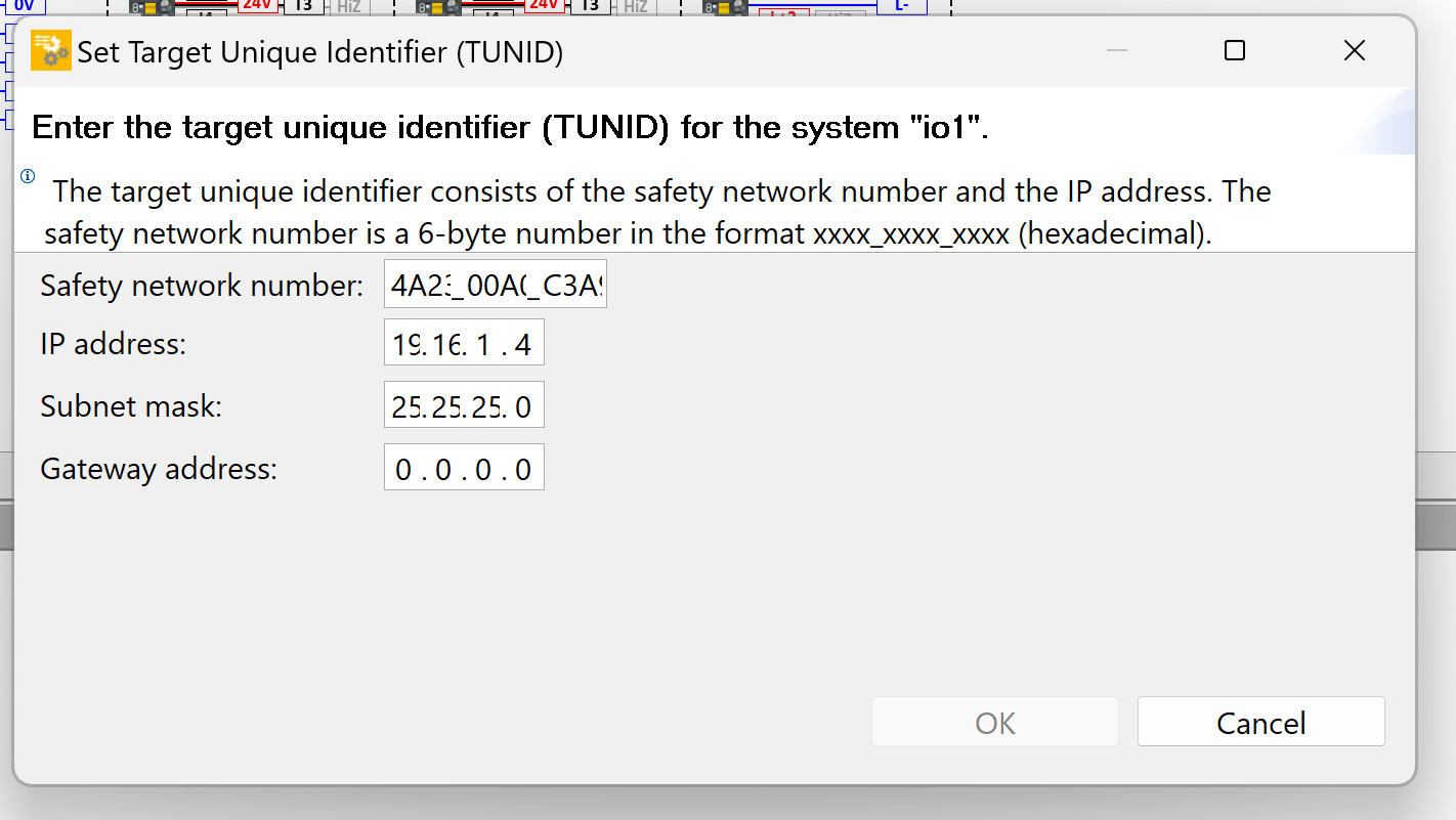
For Safety Network Number, paste the Safety Network Number displayed in Sysmac Studio; for IP Address, enter the IP address according to the Pilz CIP Safety module PSS u2 P0 F/S EIP2.
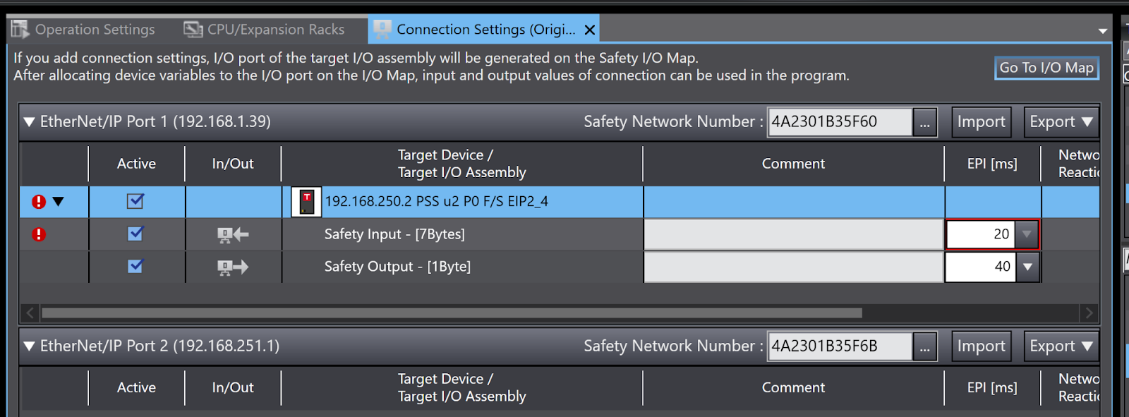
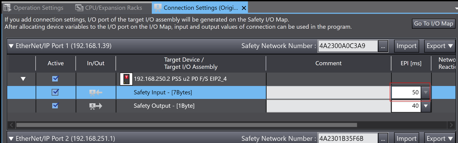
EPI
The cycle time should be set according to the application.
Configure Ethernet/IP Connections
The Pilz PSS u2 P0 F/S EIP2 used in this article has a non-safe IO-Link module installed as well as a safe IO To get data from the IO-Link module, a non-safe Ethernet/IP Connection must be built in Sysmac Studio.
Tools>Ethernet/IP Connection Settings to build an Etherent/IP connection.
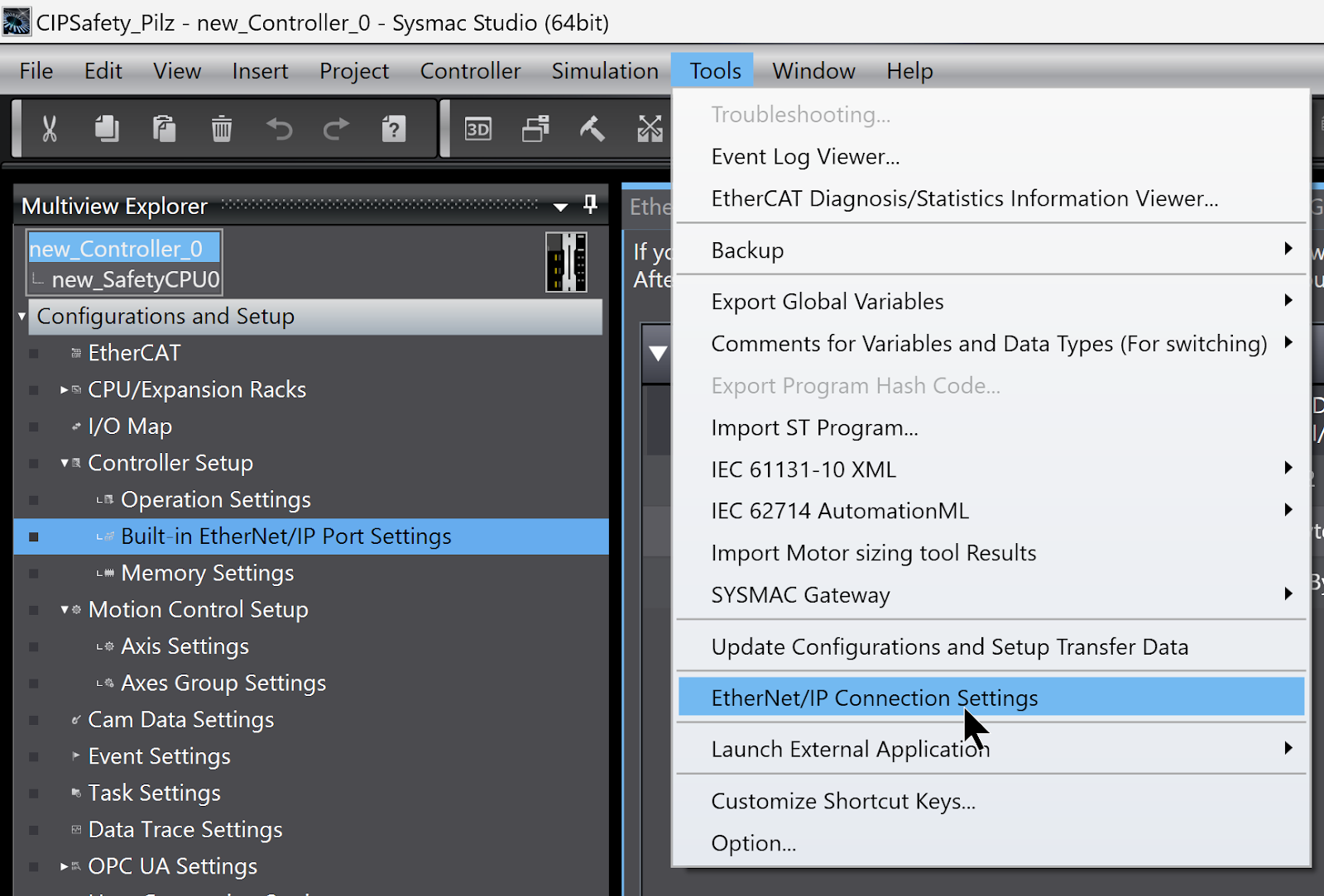
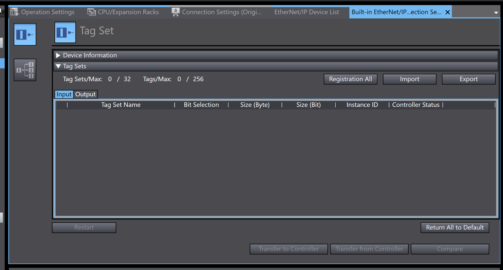
This is the Sysmac Studio Ethernet/IP configuration and monitoring screen.
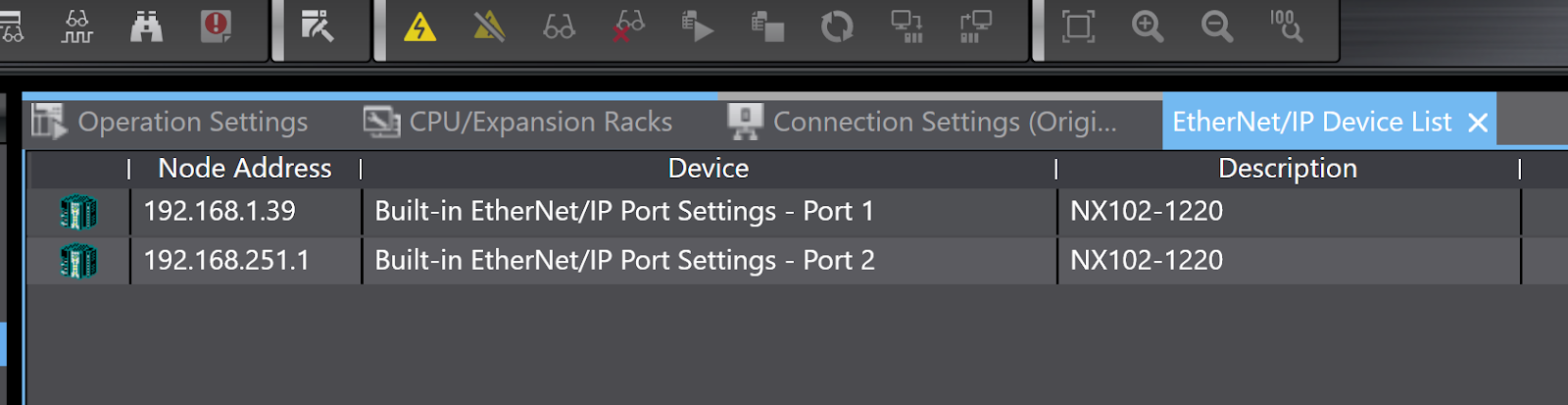
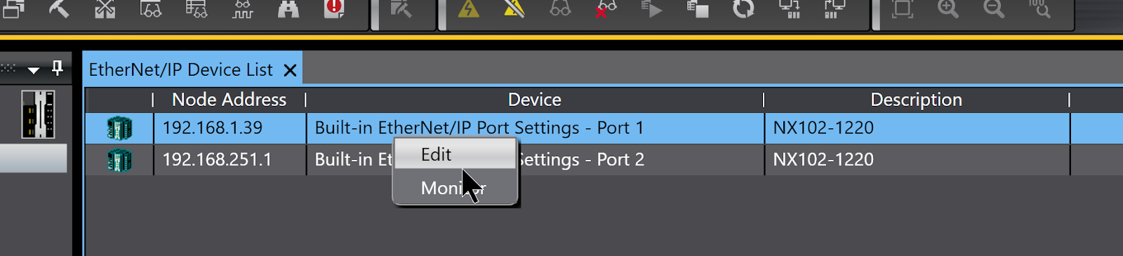
Since we are connecting the Pilz CIP Safety module PSS u2 P0 F/S EIP2 with Port 1, select Port 1 > right-click > click Edit.
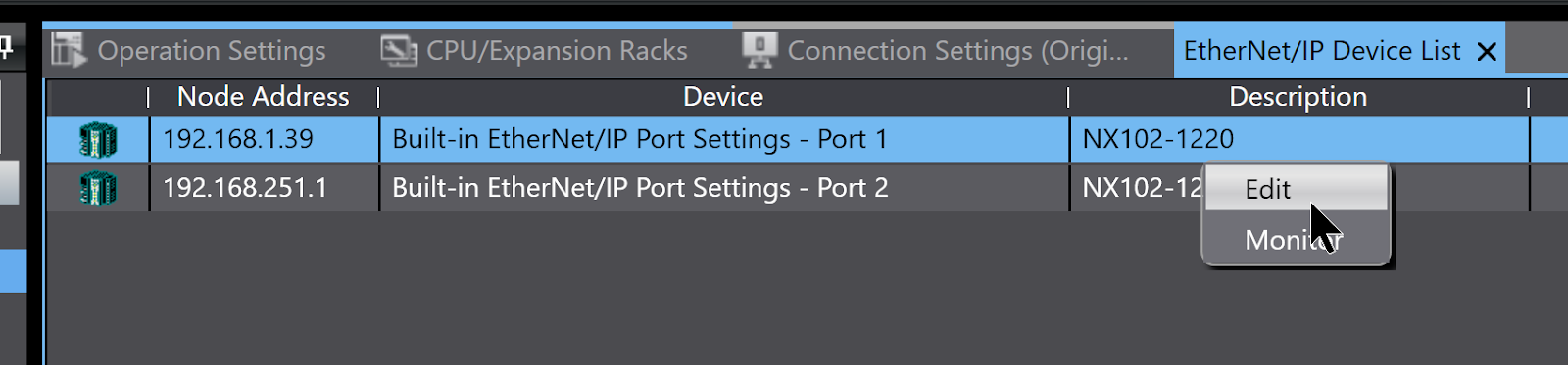
Sysmac Studio has been replaced by an Ethernet/IP Connection configuration screen.
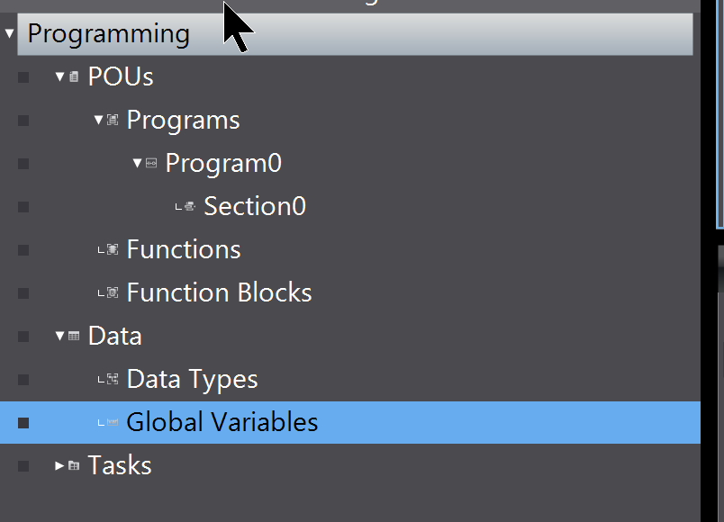
Define Global Variables
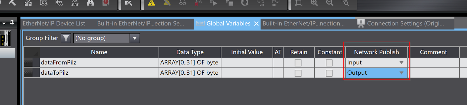
Define Global variables in Data>Global Variables. These variables are used as input and output data for the Etherent/IP Connection.
In this article, two 32 Bytes array variables are defined and Network Publish is set to one Input/Output each.
Registration
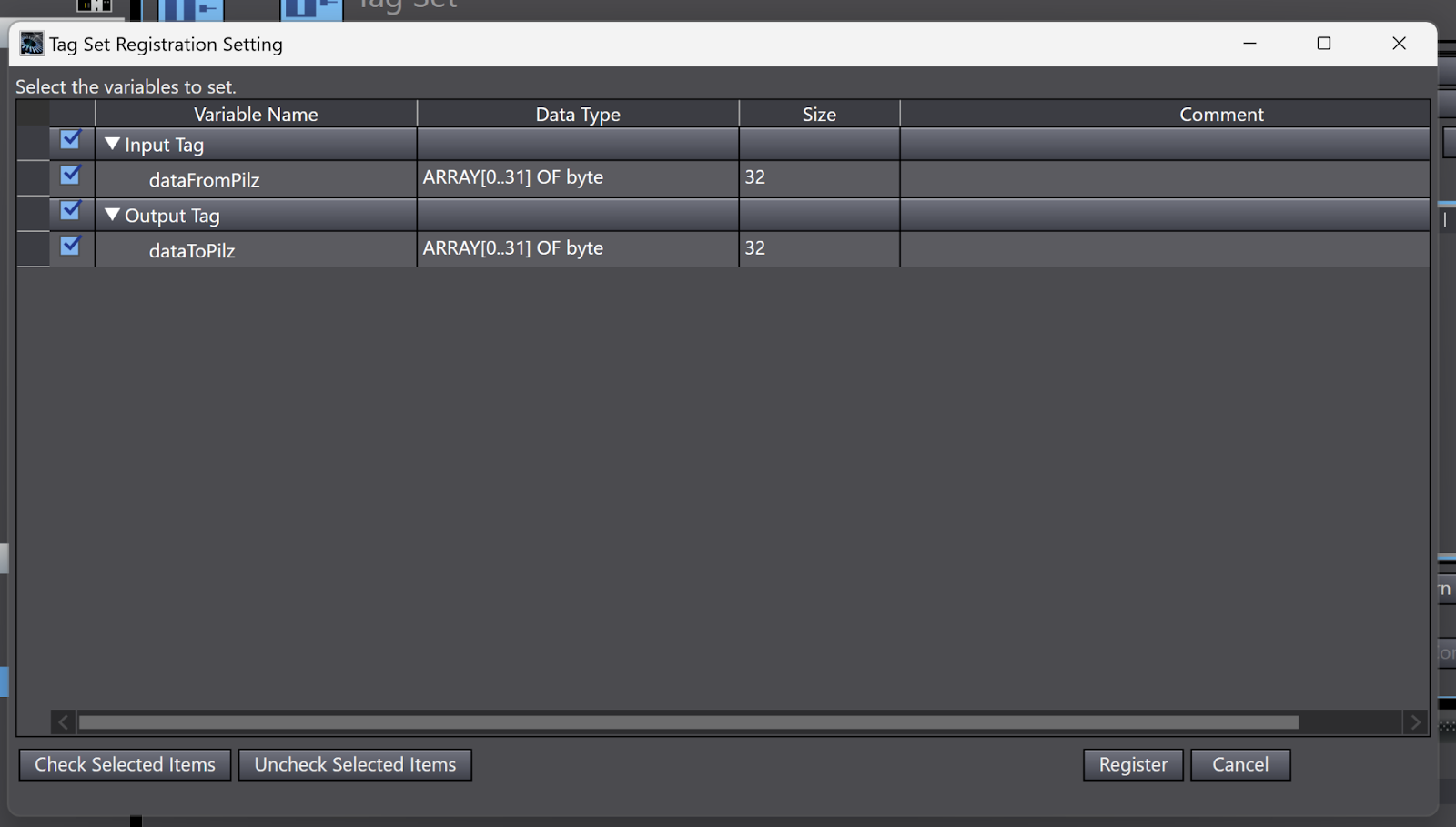
Next, return to the Ethernet/IP Connection configuration screen in Sysmac Studio and click Tag Set screen > Registration All to register the Global variable.
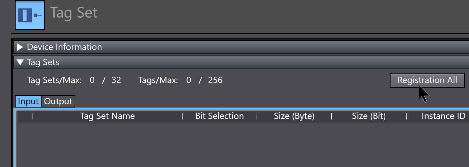
Register the Global variable you defined earlier.
Done!

Connections
The next step is to create Ethernet/IP Connectons.
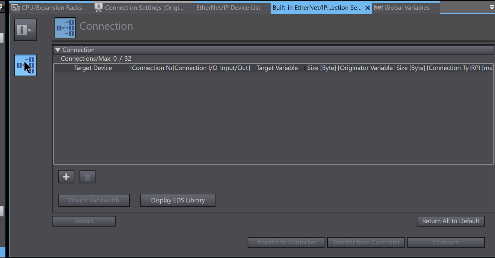
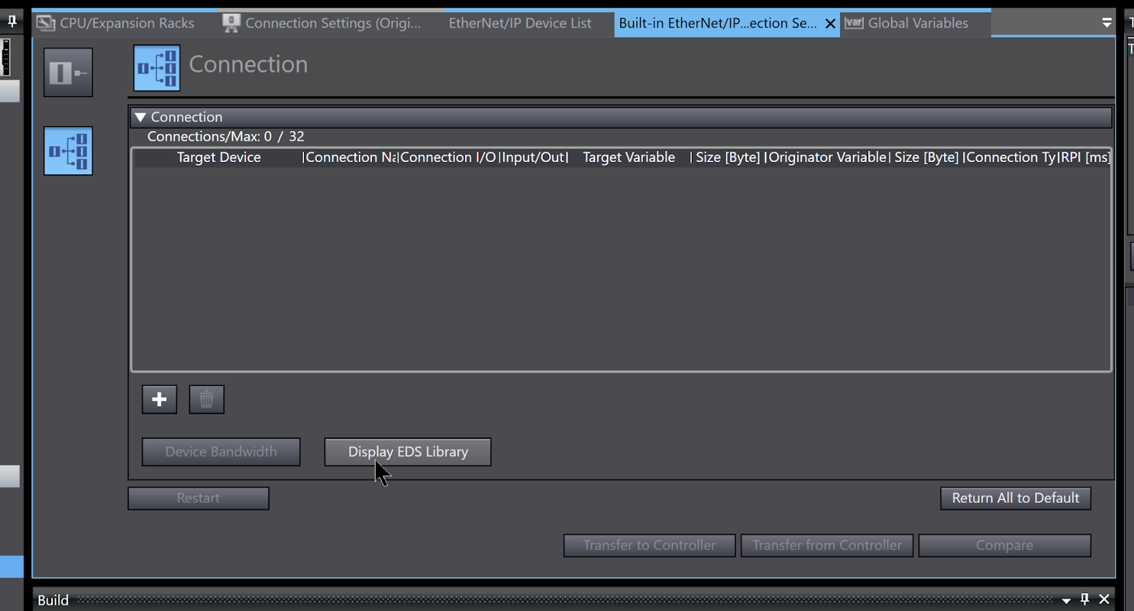
Install EDS File
To install the Pilz EDS File, click Display EDS Library.
The EDS Library screen is displayed and the Install button is clicked.
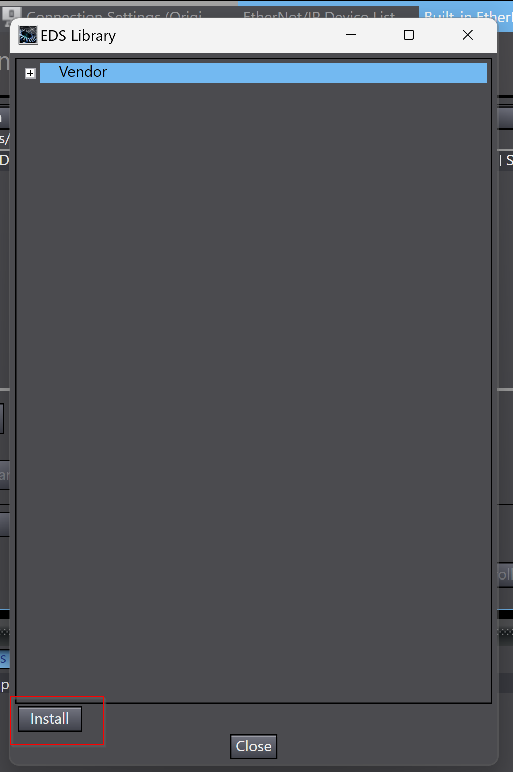
Open the EDS File downloaded from Pilz HP.
Done!
Add Target Device
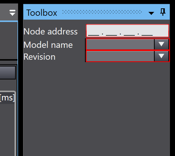
Now add a Target device. Create a Pilz Ethernet/IP device using the EDS File you have just registered. First, click on the + button from the Toolbox.
New Target devices have been added.
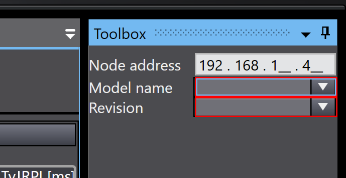
Node Address
The Node Address is matched to the IP address set in Pilz’s PSS u2 P0 F/S EIP2.
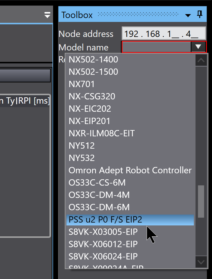
Model Name
For Model Name, select PSS u2 P0 F/S EIP2.
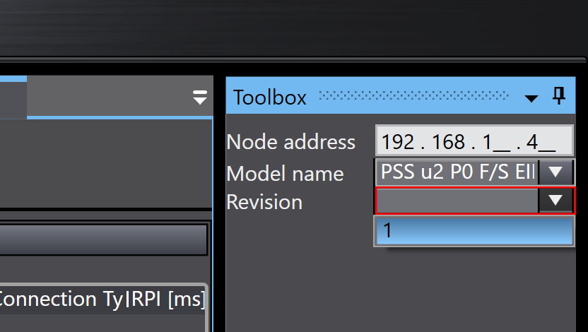
Revision
Revision is 1.
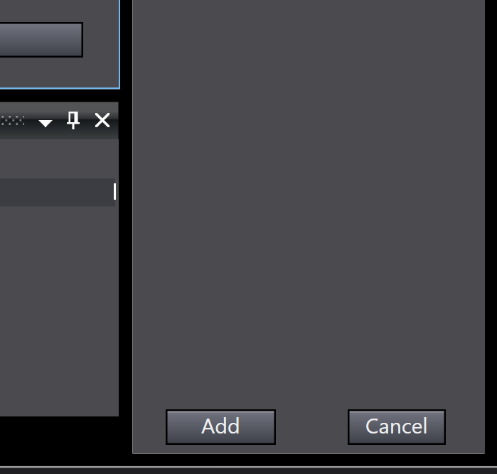
Add
Finally, use the Add button to add a Target device.
Result
Done!
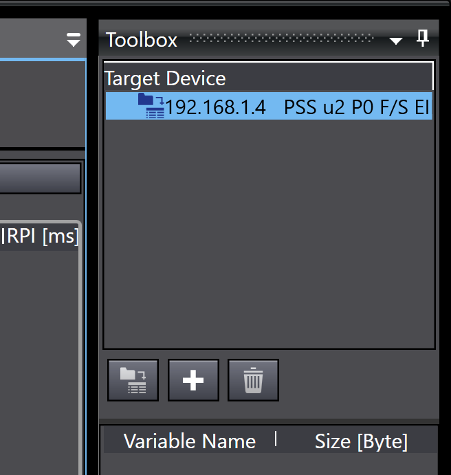
Add Connection
Select the Pilz PSS u2 P0 F/S EIP2 you have just added > right-click > Add Connection.
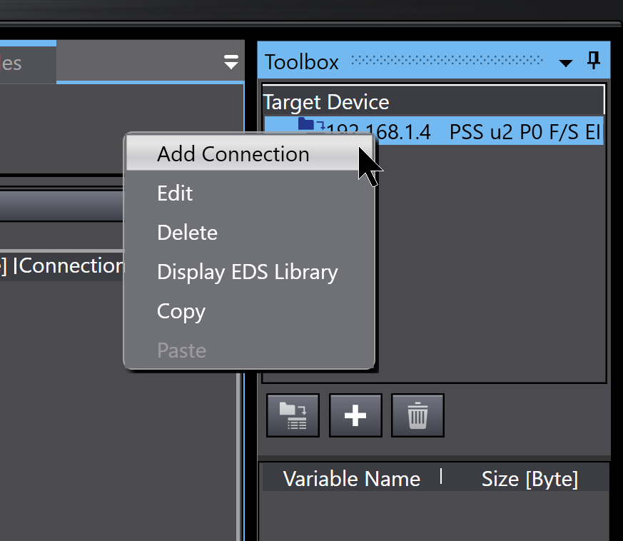
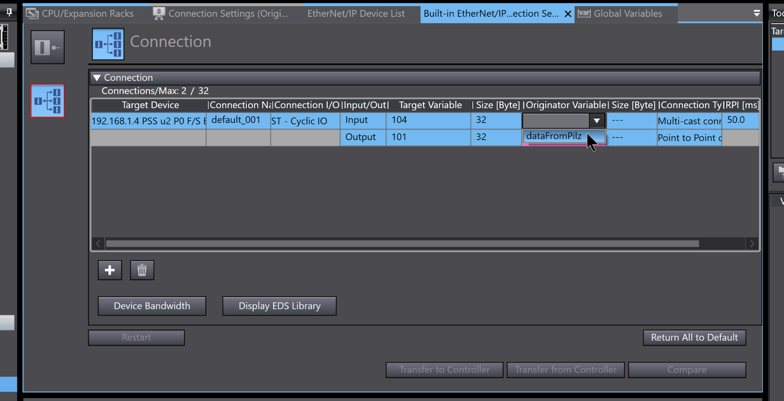
Done!PSS u2 P0 F/S EIP2 has been added to Sysmac Studio’s Etherent/IP Connection.
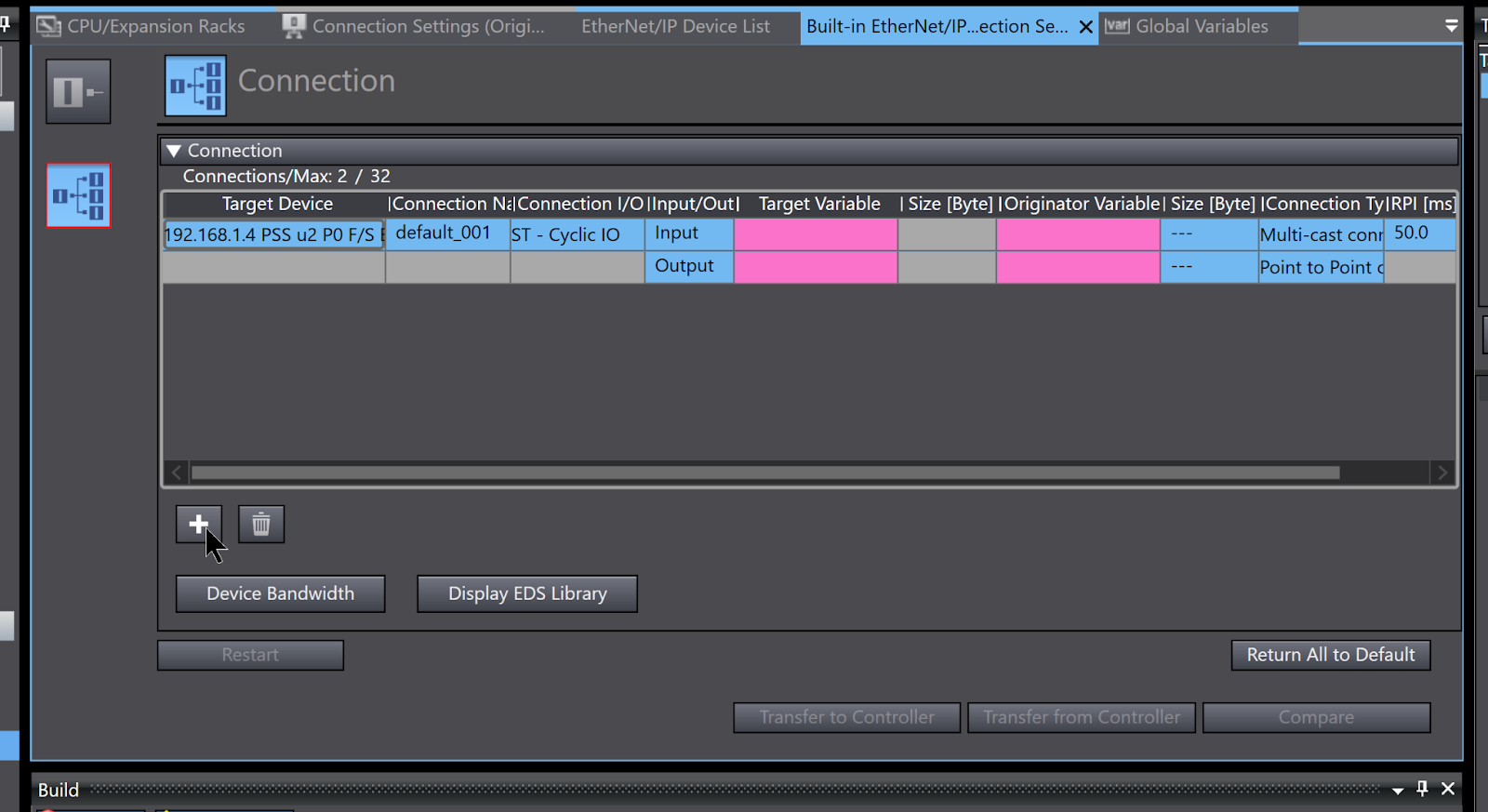
The Target Variable is the Instance number of the PSS u2 P0 F/S EIP2.
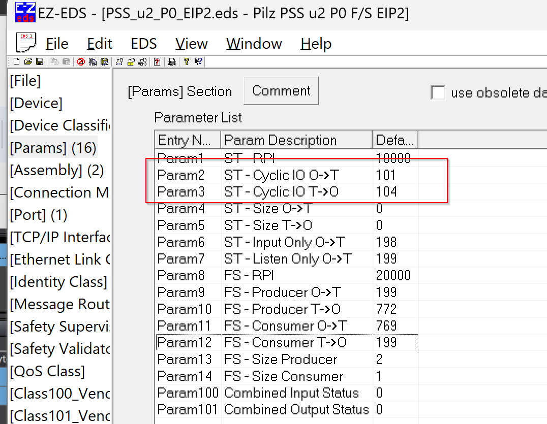
Input=104, Output=101.
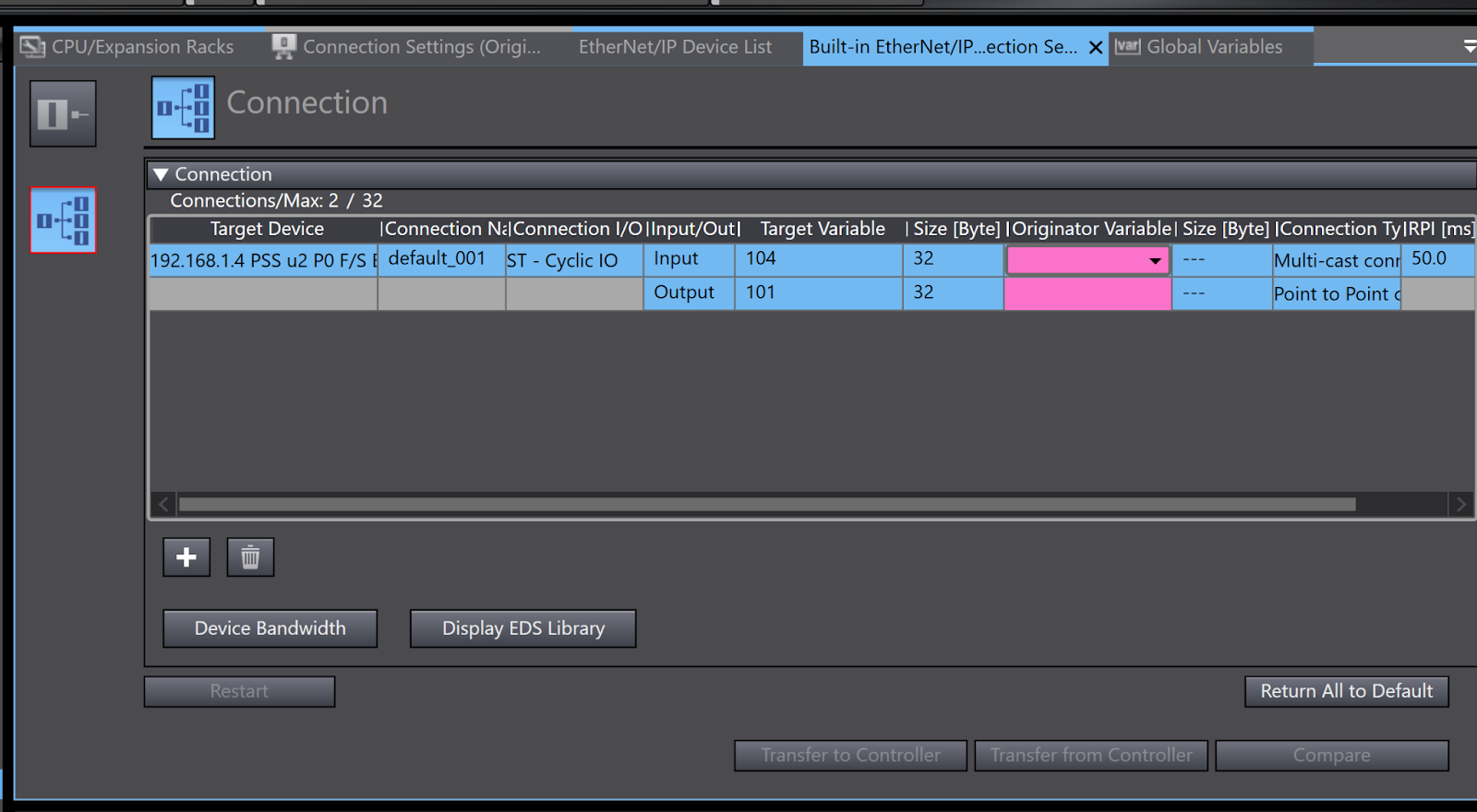
These figures can be found in the EZ-EDS tool.
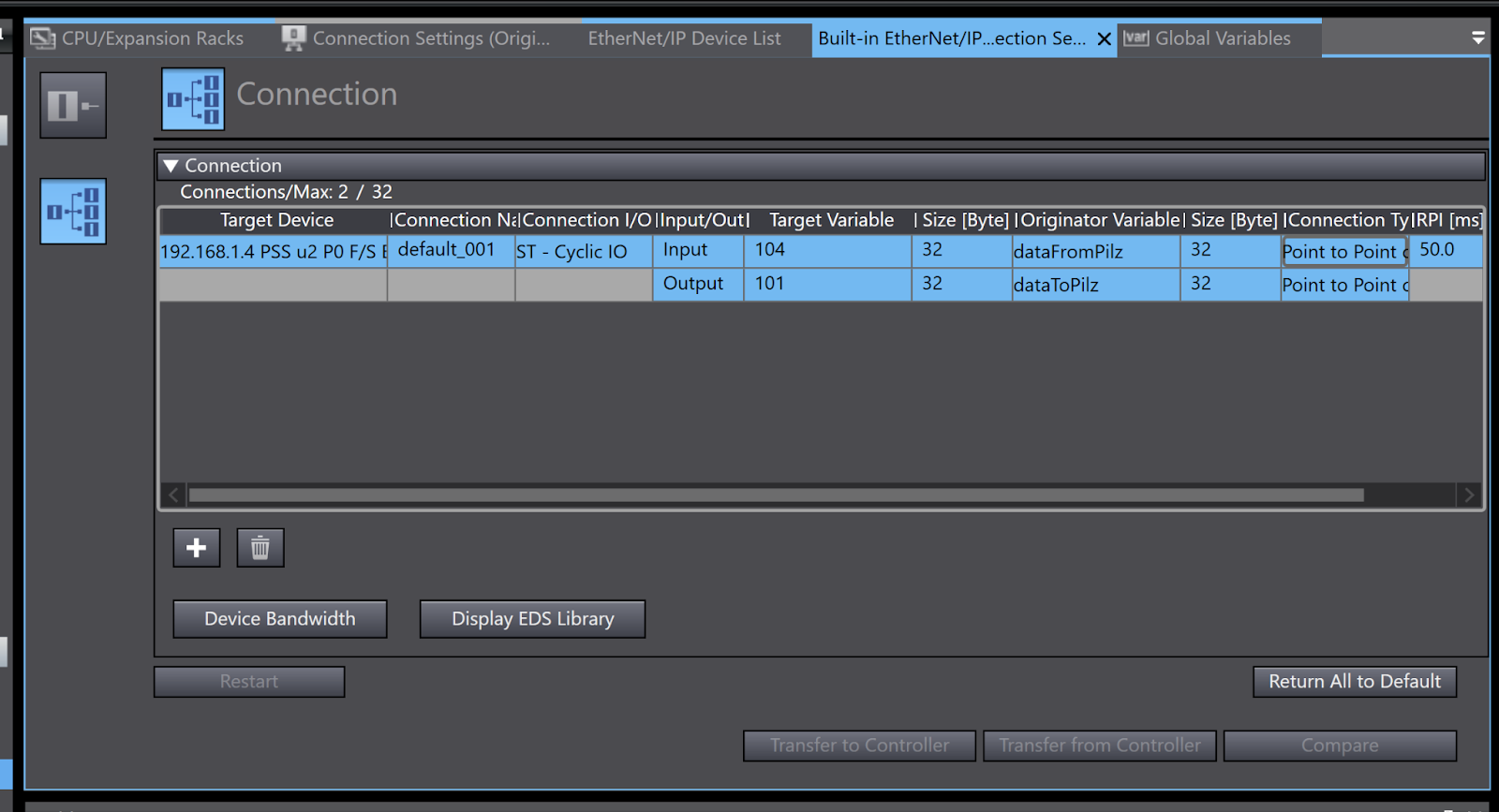
For Size (Byte), enter 32 and for Originator Variables select the Global Variables you have just registered.
Done!
Download Safety
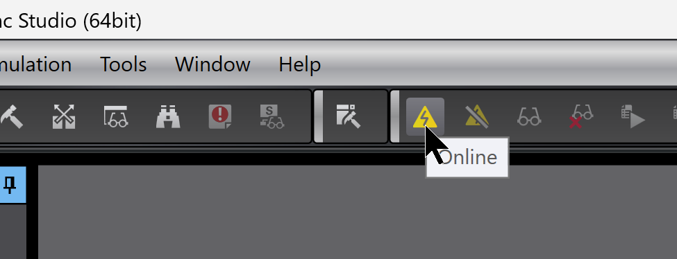
Download the Safety data first.
Go Online.
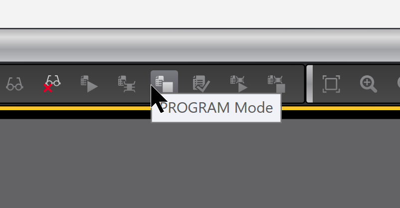
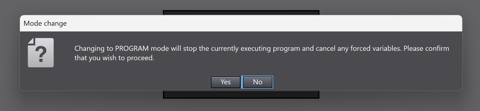
Switch the CPU to PROGRAM Mode.
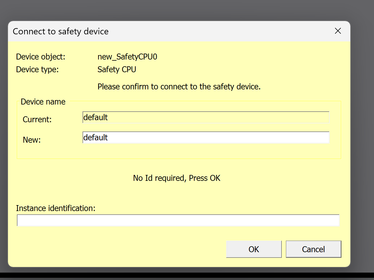
Proceed with Yes.
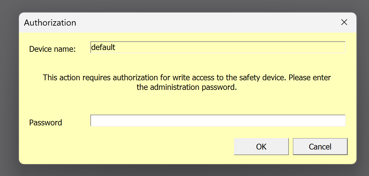
Enter Password and proceed with Ok.
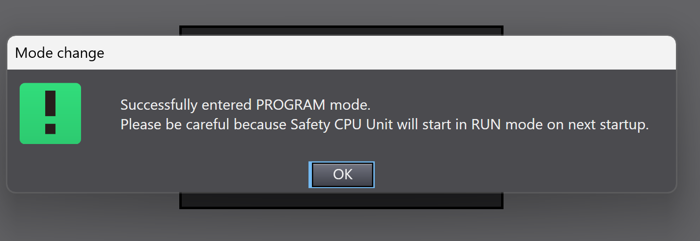
CPU changed to PROGRAM Mode.
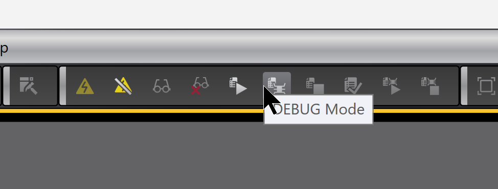
Now switch to DEBUG Mode.
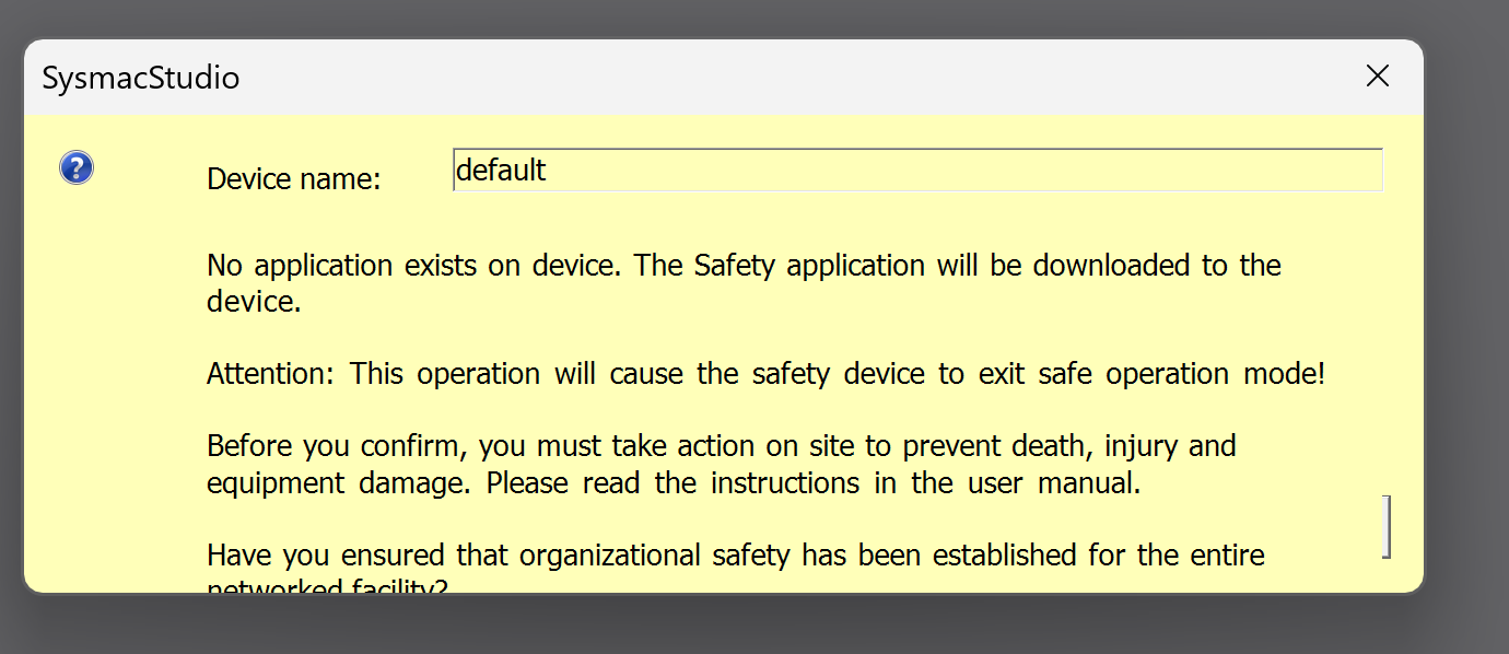
Proceed with Yes.
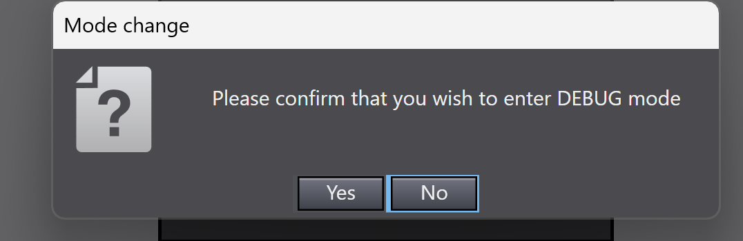
Proceed with Yes.
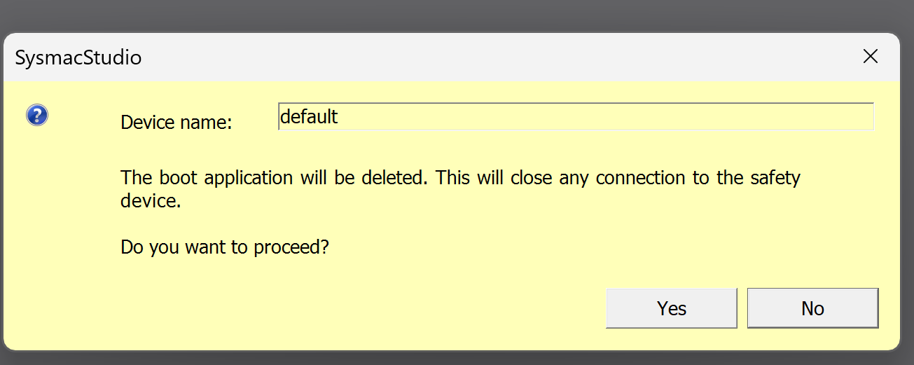
The CPU has now changed to Debug Mode.
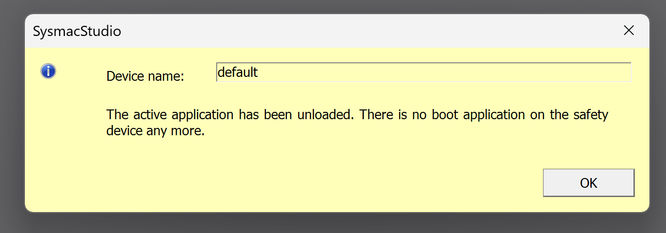
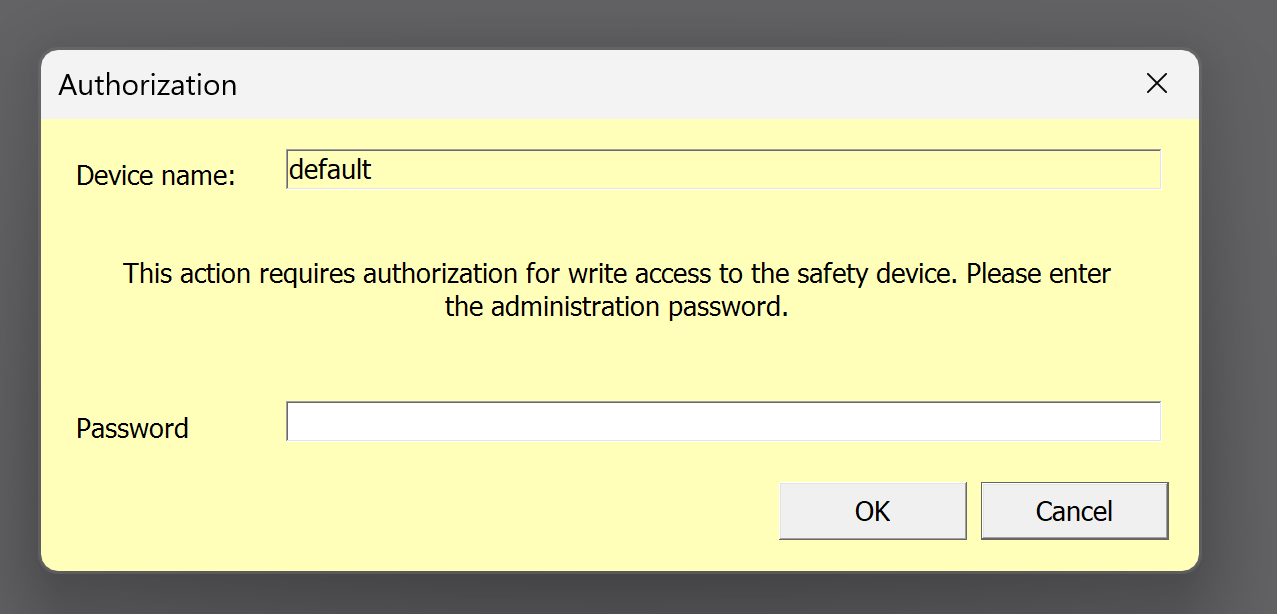
Proceed with Ok.
Proceed with Ok.
Enter the Password and you are OK.
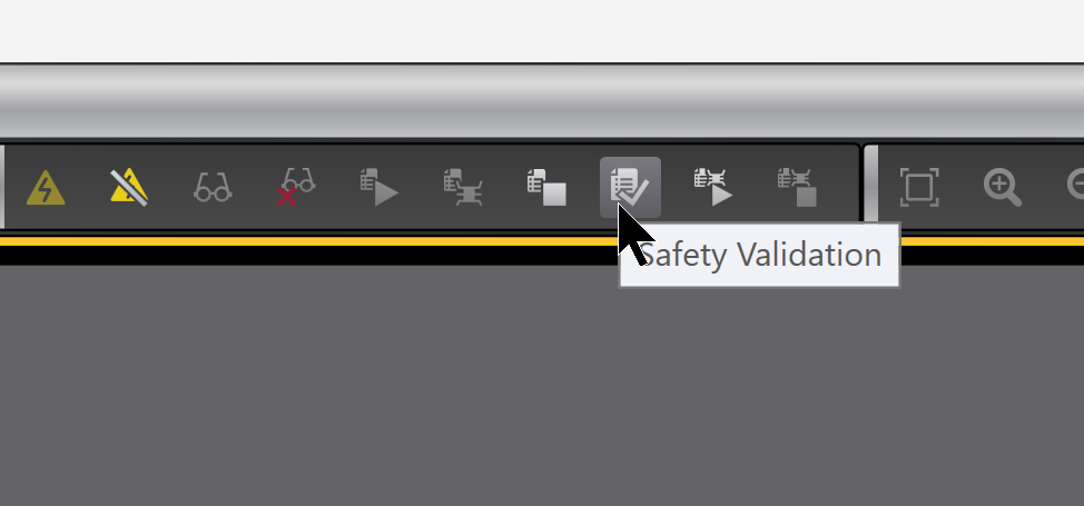
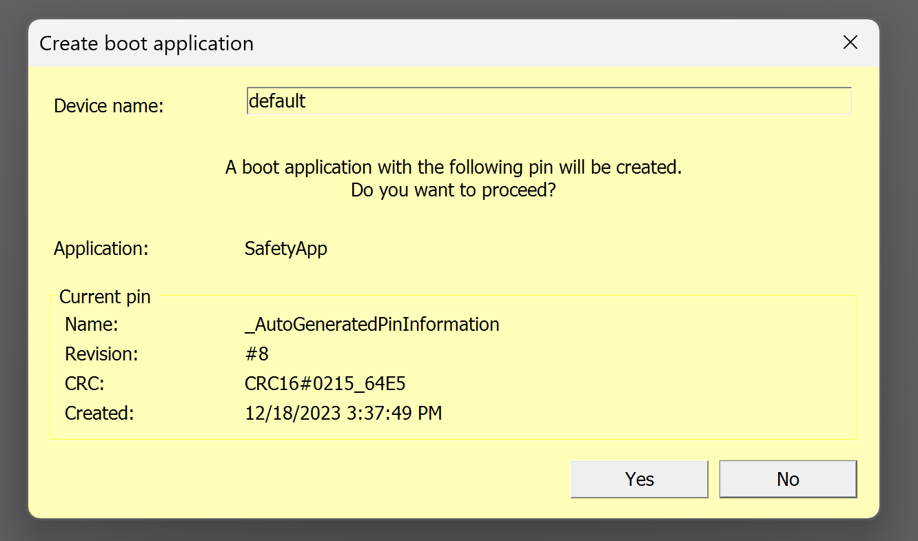
Finally, click on Safety Validation and download the Safety configuration and programme.
Proceed with Yes.
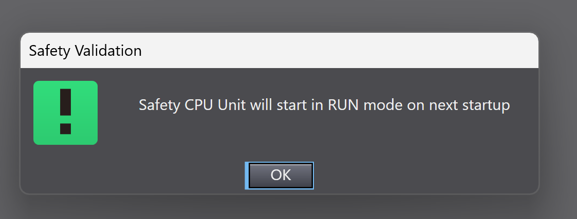
OK to proceed.
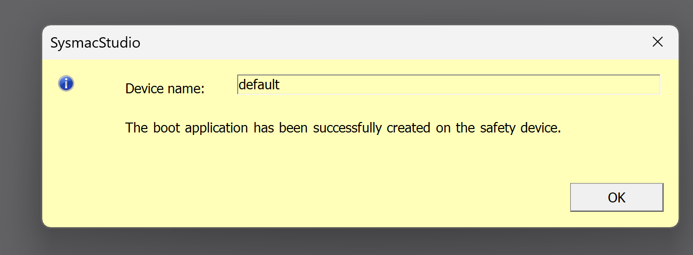
Done!Safety Project is Downloaded.
Download Project
Now download the project of the CPU itself to the CPU.
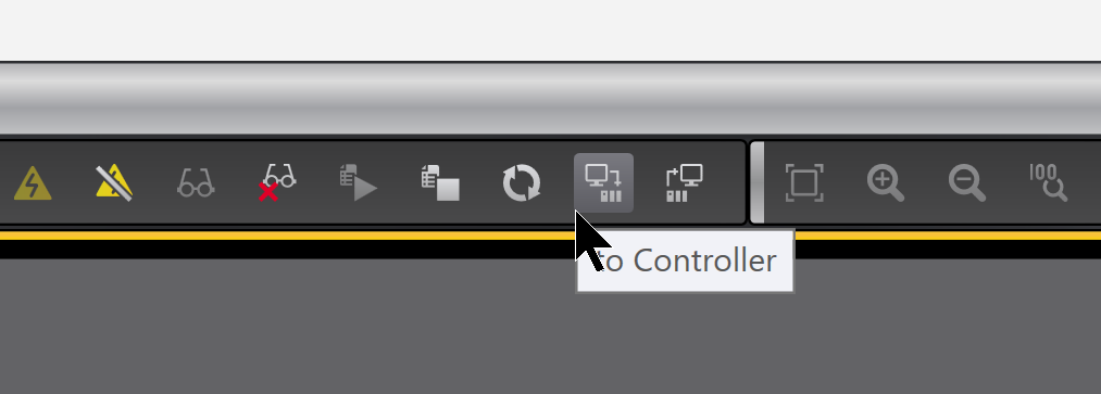
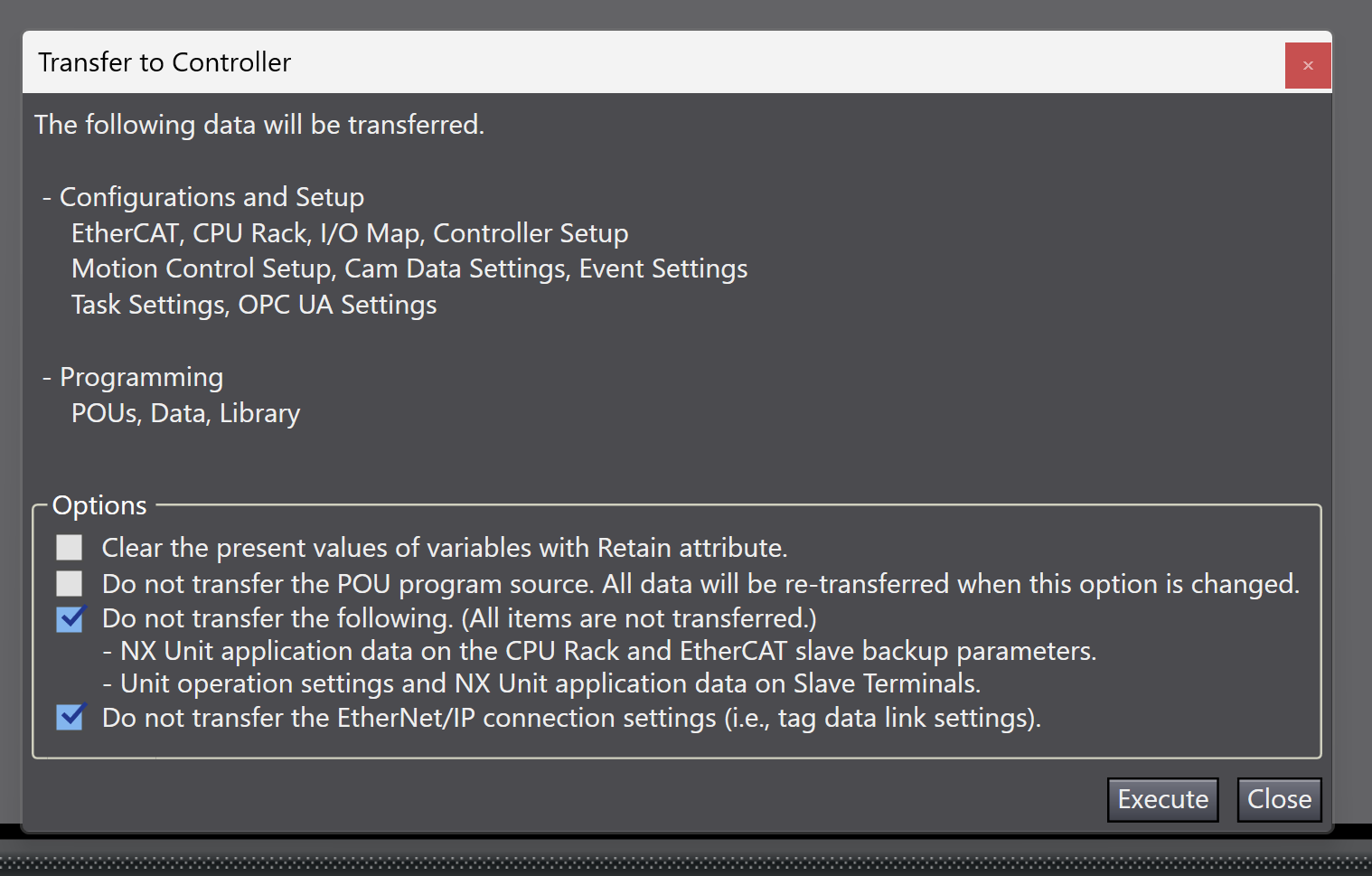
Click To Controller to Dowload the project to the CPU.
Proceed with Execute.
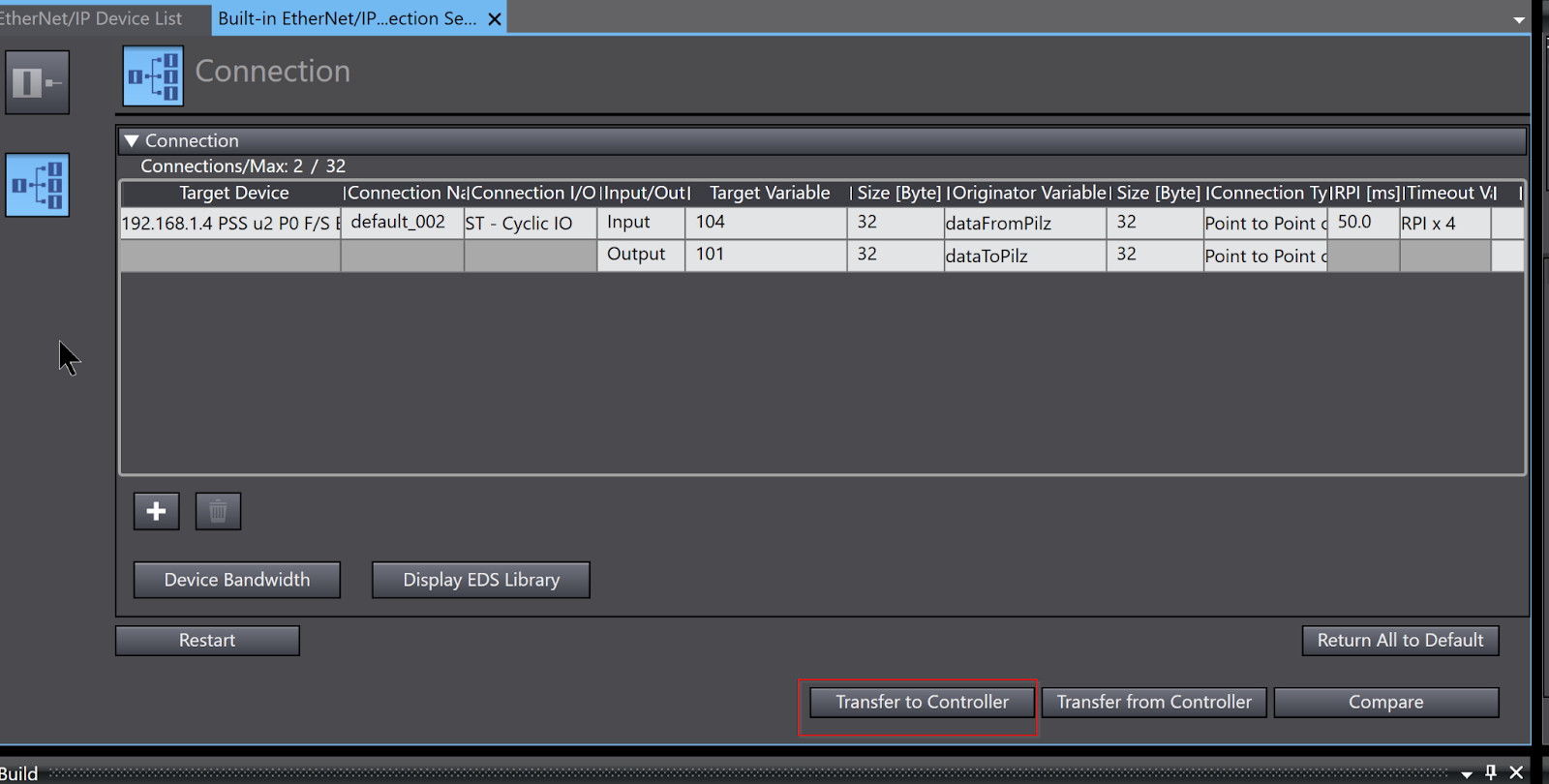
Download Etherent/IP Configuration
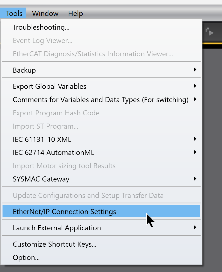
Next, click Tools>Ethernet/IP Connection Settings to Download Ethernet/IP Configuration to the CPU.
Click on Port1 in Edit.
Connection Switches between screens.

Transfer to Controllerをクリックし設定をCPUに転送します。
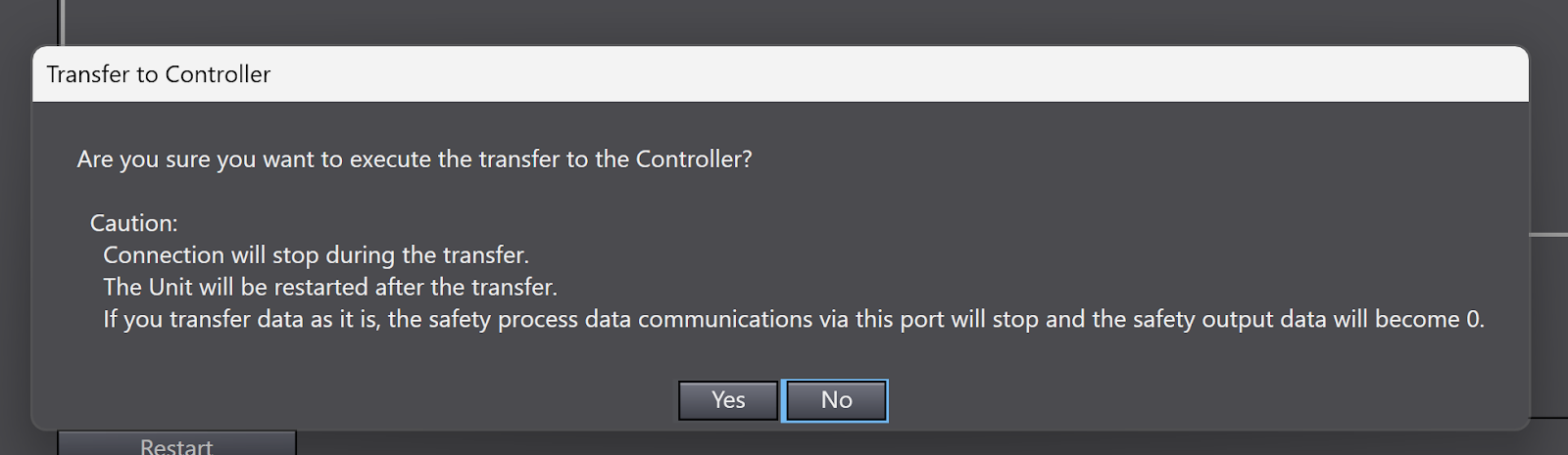
Proceed with Yes.
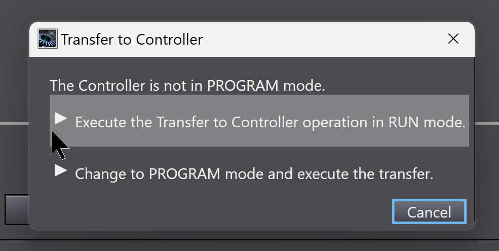
This time, the Configuration is transferred with the CPU in Run Mode.
Result
To check the Ethernet/IP connection, Port1>Right-clickMonitor.
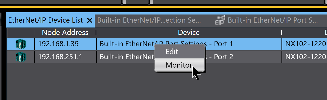
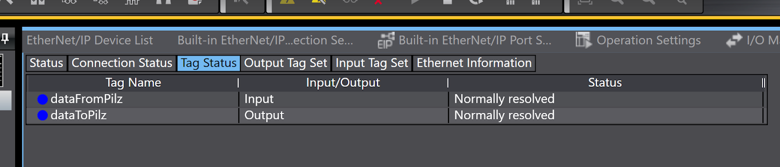
The screen has changed to the Monitor screen for Ethernet/IP.
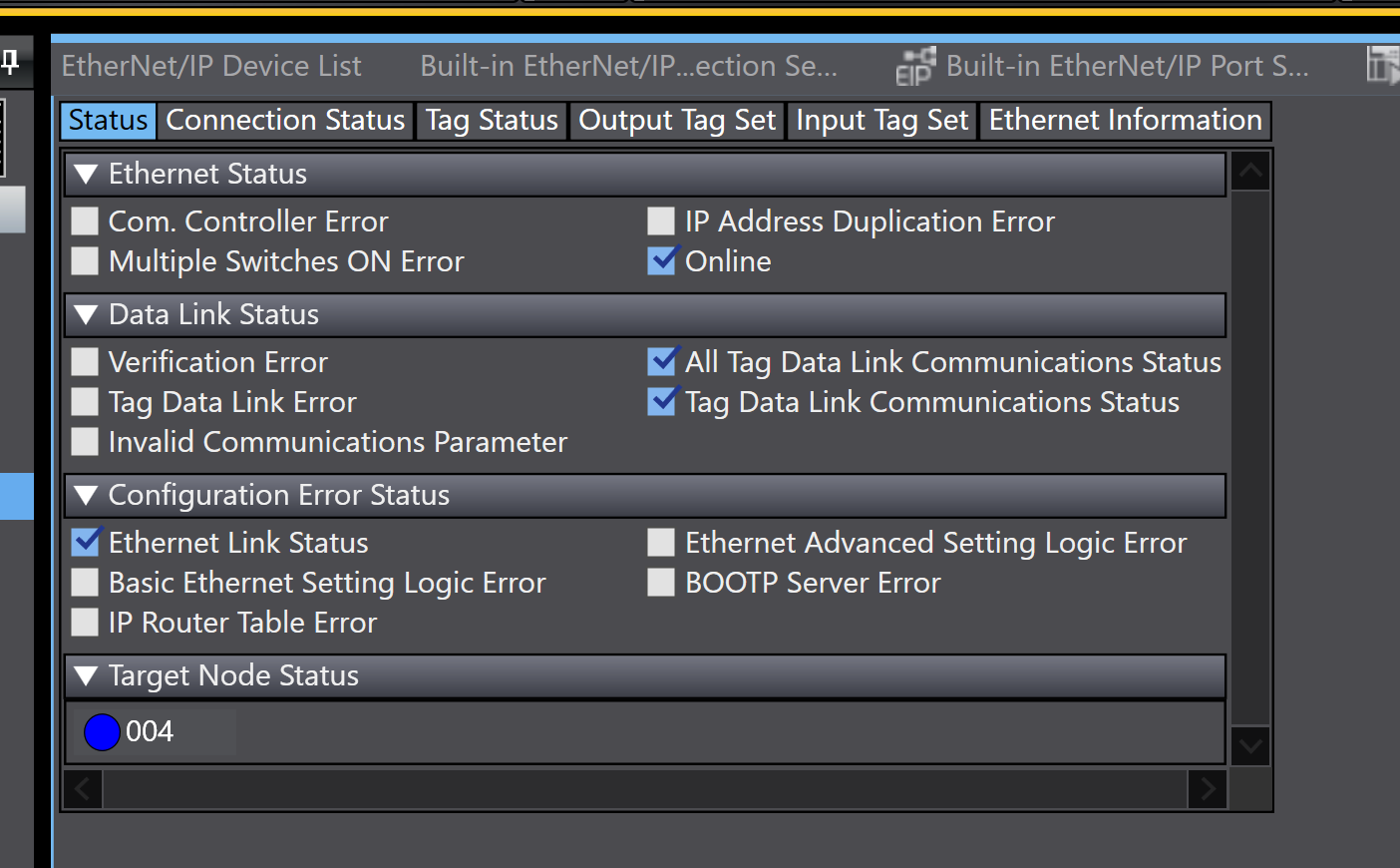
The current Connection status can be checked from the Tab in Tag Status. It is now in a normal state.
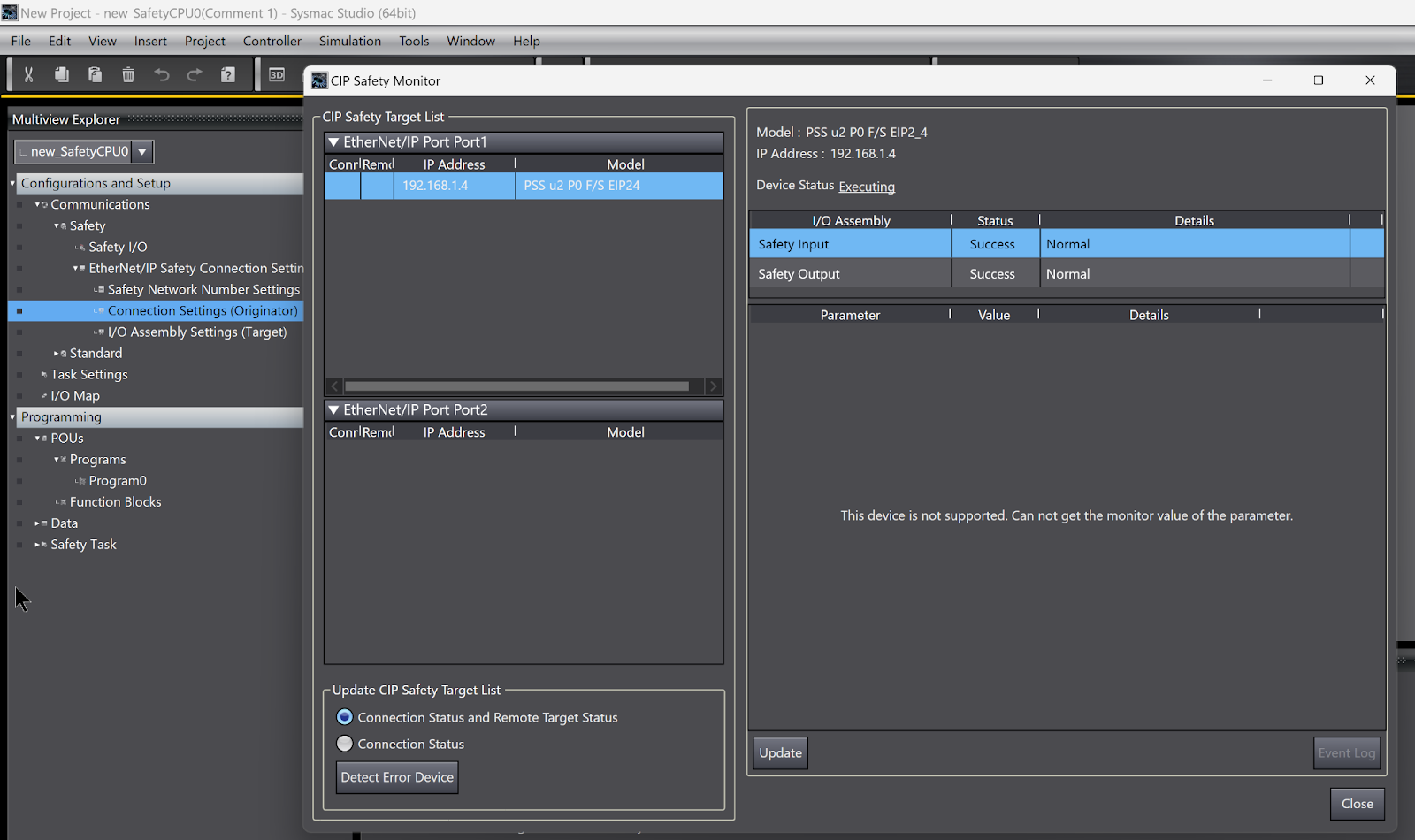
CIP Safety communication is also Ok!
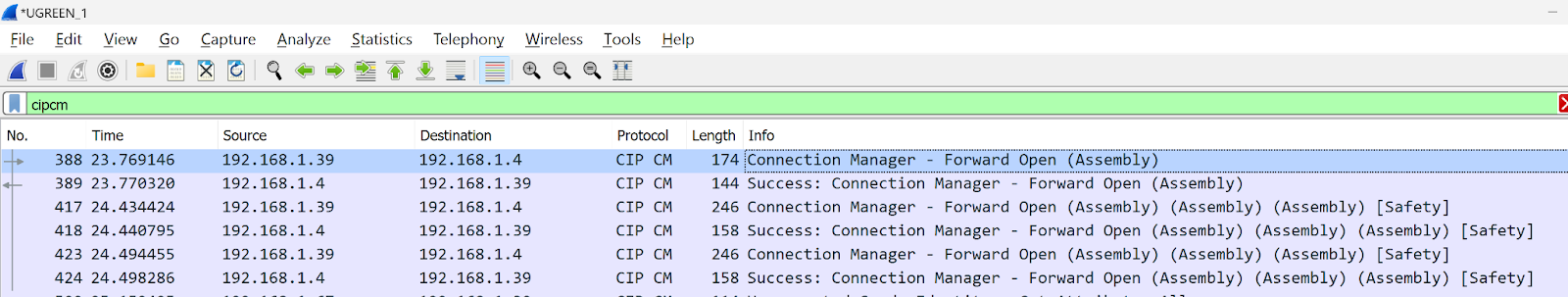
There was also a CIP CM Successful Reply Packages from WireShark!
Download EDS File
Please Download the EDS File for Pilz PSS u2 P0 F/S EIP2 from this Link.
https://github.com/soup01Threes/OMRON/blob/main/00B5_00FF_PSS%20u2%20P0%20FS%20EIP_2F47B597.eds