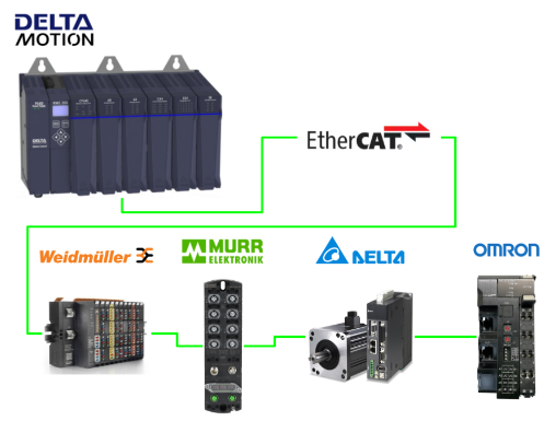
In this article, the newly released ECAT module from DELTA Motion is used to build an EtherCAT network. The article uses Slave from Weidmuller, MURRELEKTRONIK, DELTA and OMORN.
Come on, let’s enjoy FA.
ECAT Modules?
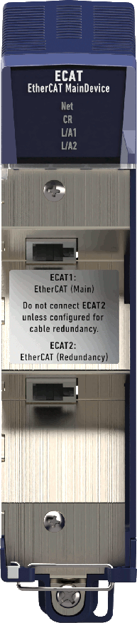
ECAT modules provide EtherCAT main device functionality, enabling control of electric motor drives and communication with other EtherCAT subordinate devices such as sensors and actuators. Its ECAT module has two RJ-45 ports and the ECAT module supports cable redundancy.
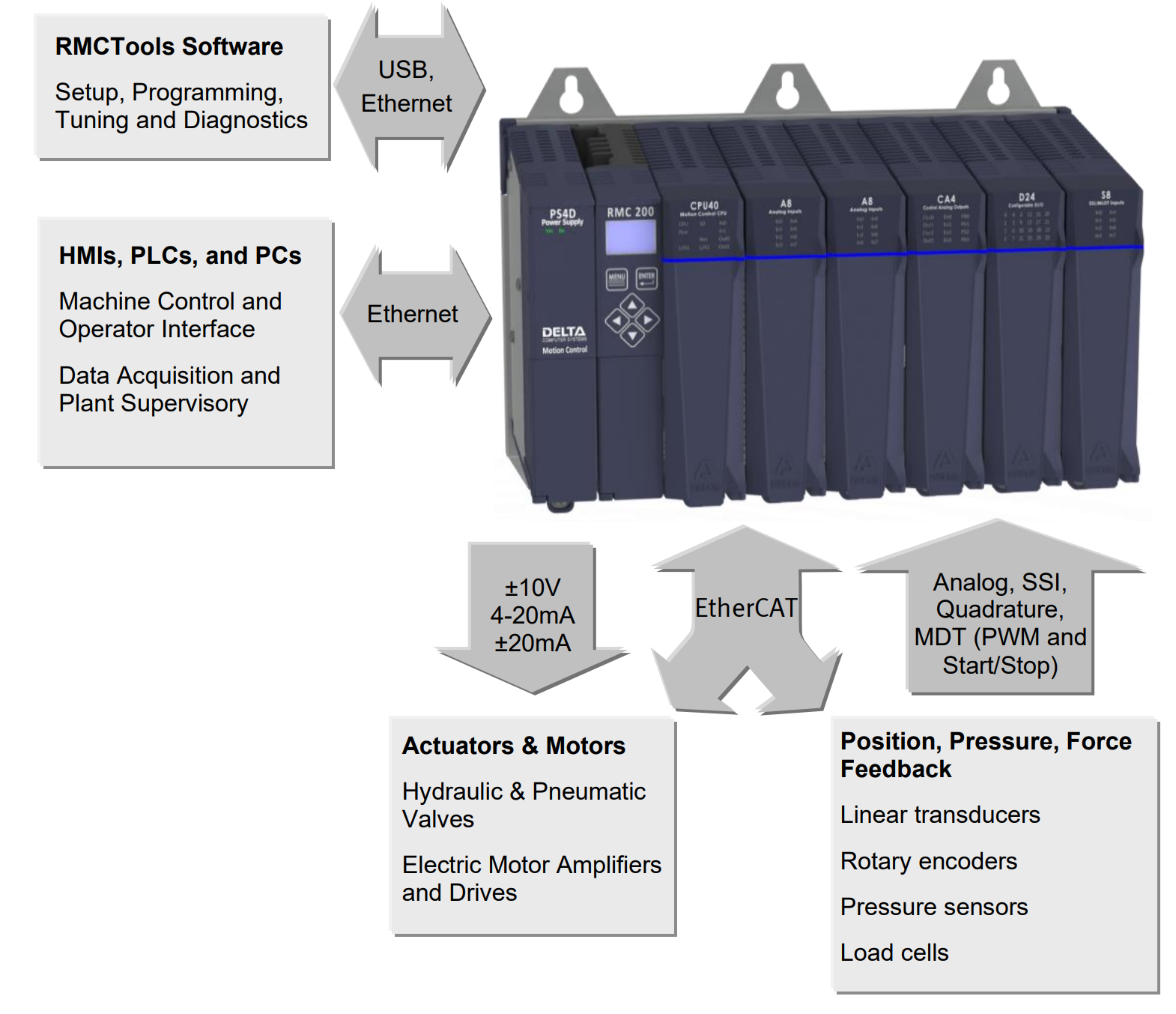
The RMC200 supports position, speed, pressure, force and torque control, single and dual loop axes via EtherCAT. Axes can define outputs and feedback with any combination of EtherCAT data or directly connected sensors and actuators.RMC200 EtherCAT supports CANopen over EtherCAT (CoE) CiA402 drive profiles and CiA408 valve profiles are supported.
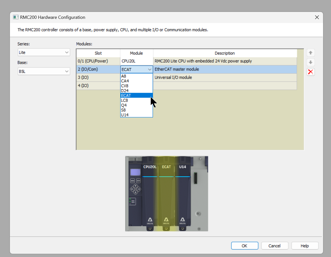
ECAT modules are also supported on all RMC200 bases and can only be installed in slot 2 (slot immediately to the right of the CPU) LED indicators show network status, redundancy status and status of individual ports.
This is the specification for the ECAT module.

The ECAT module enables simple connection to EtherCAT Slaves from other manufacturers, making it possible to build independent systems.
Reference Link
Install the latest Version OF RMC Tools
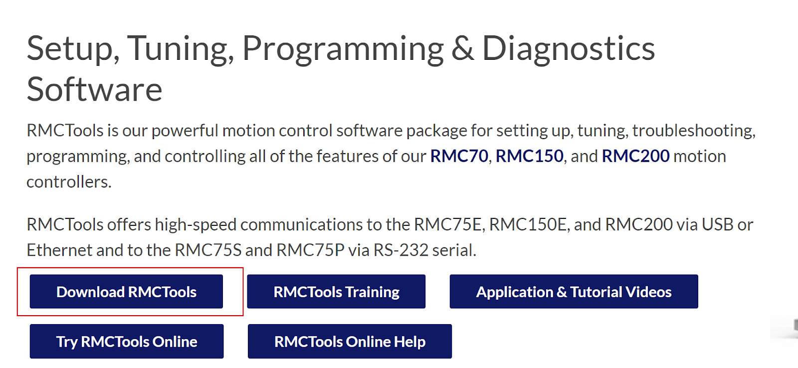
To use Deltamotion’s ECAT modules, use the latest version of RMC Tools. The latest version of RMC Tools can be downloaded from the link below.
https://deltamotion.com/products/software/rmctools
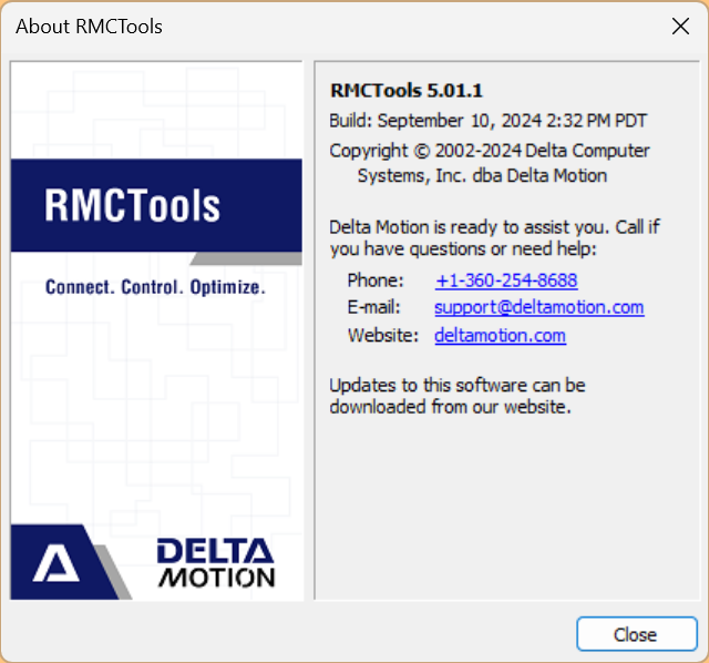
This is the RMC Tools version used in this article.
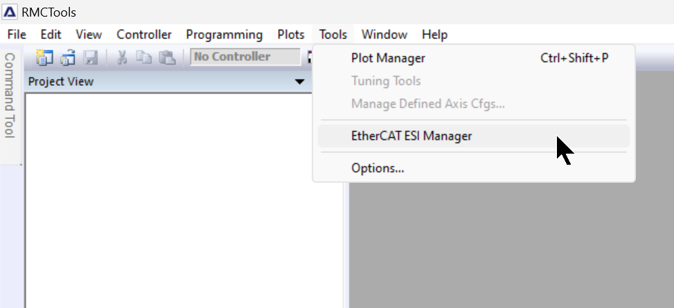
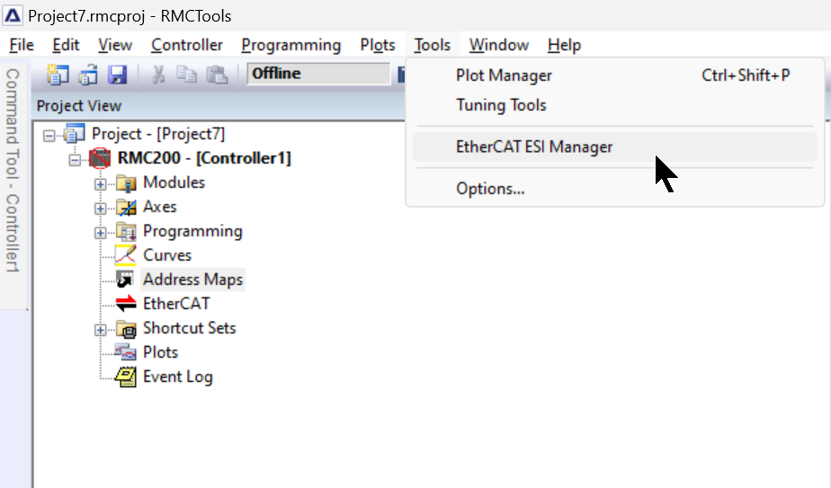
In the latest version of RMC Tools, a new item called EtherCAT ESI Manager appears from the Tools Menu.
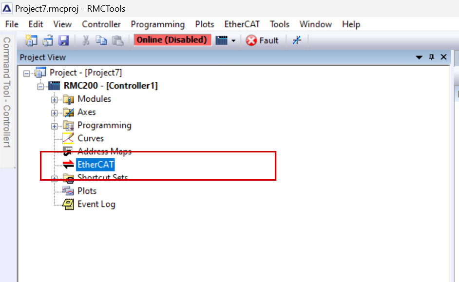
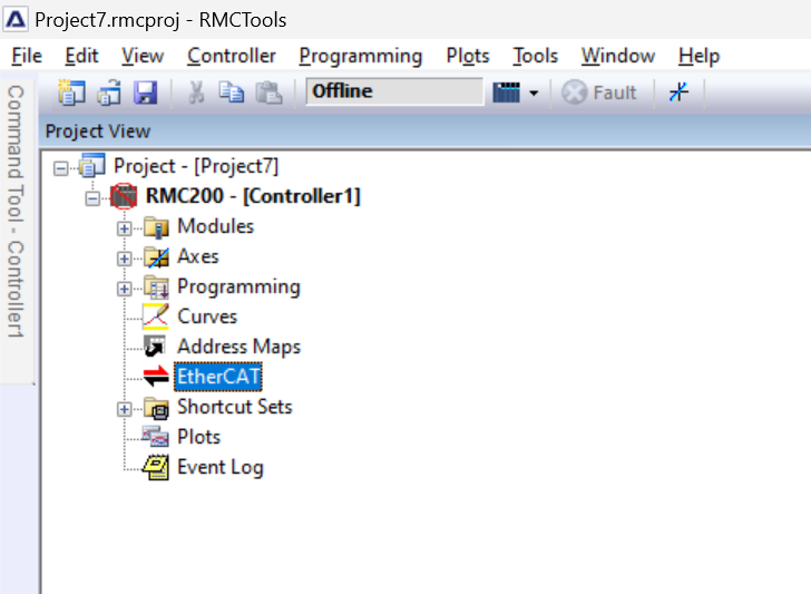
The EtherCAT entry will also appear once the ECAT module has been added.
Implementation
Add EtherCAT Module
First, add the ECAT module to the RMC project.
Install ESI File
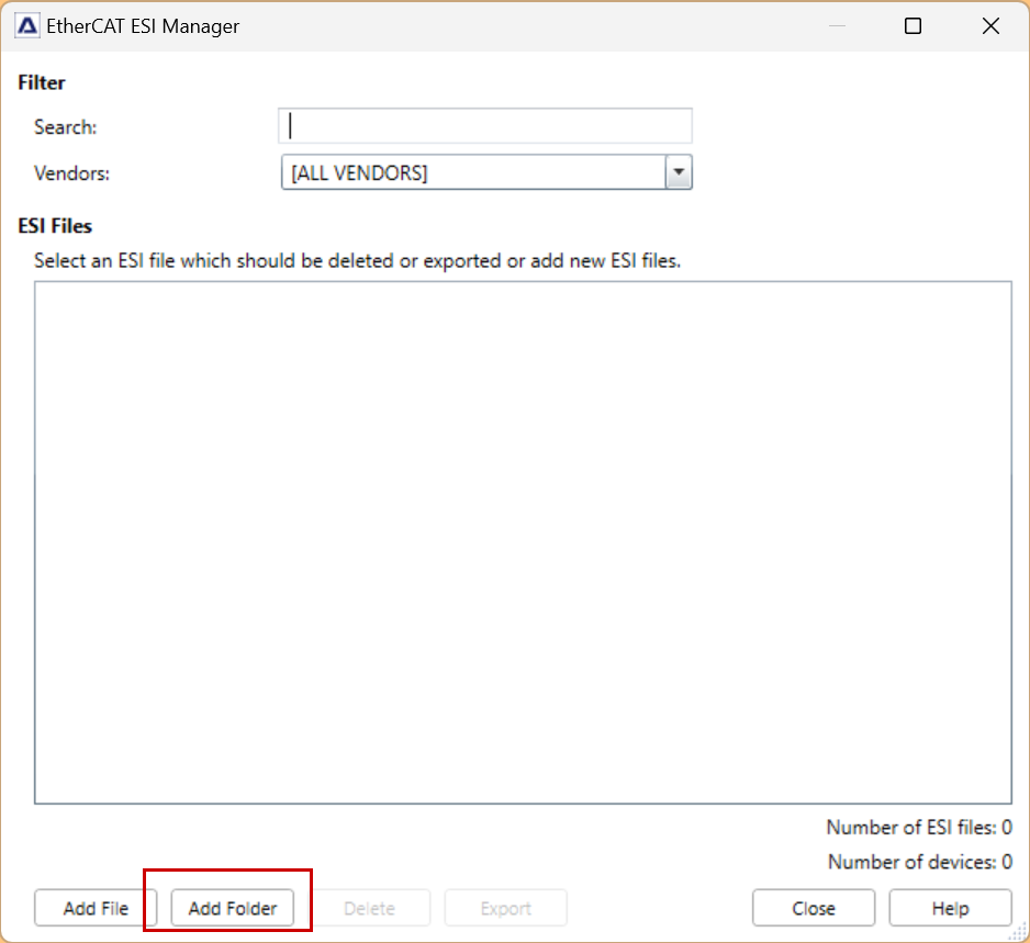
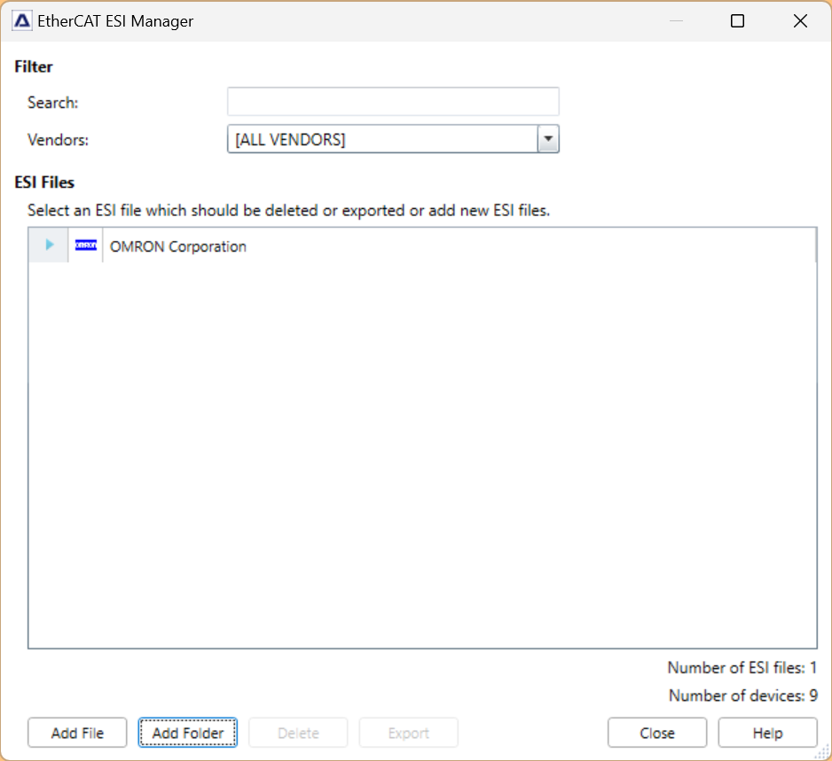
Next, click on Tools>EtherCAT ESI Manager and install the EtherCAT ESI File.
Click Add Folder.
Import the ESI File downloaded from the respective manufacturer’s website.
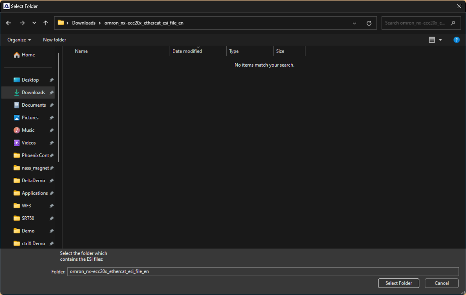
Done!The ESI File has been imported.
Configure EtherCAT Network
To set up an EtherCAT network from RMC Tools, click on the EtherCAT icon.
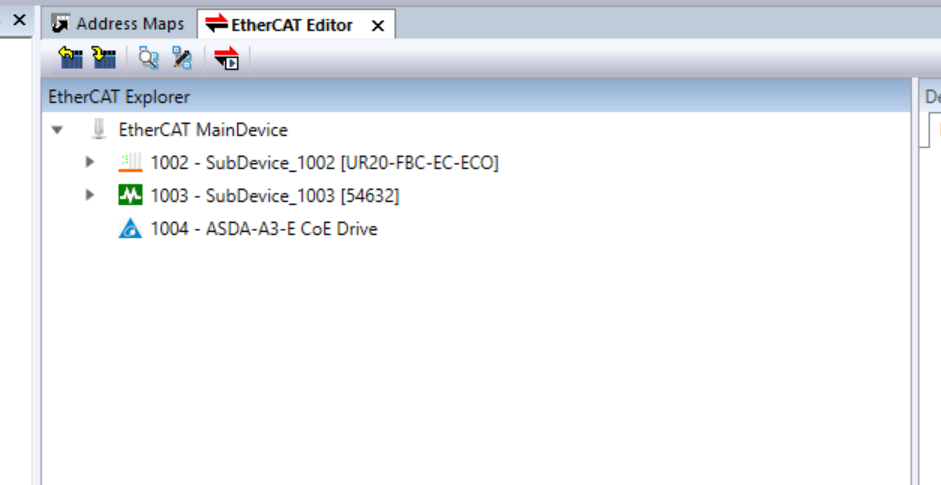
This is the EtherCAT Slave build screen.
Add EtherCAT Slave
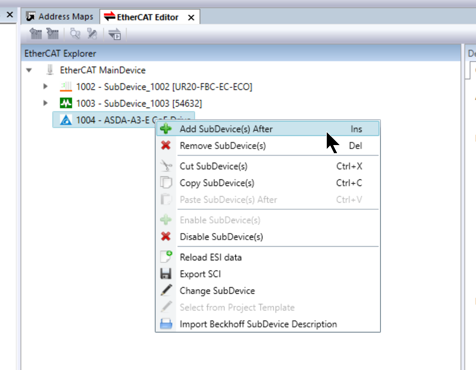
To add a Slave to the EtherCAT network, right-click on the location where the Slave is to be added>Add SubDevice(s) After.
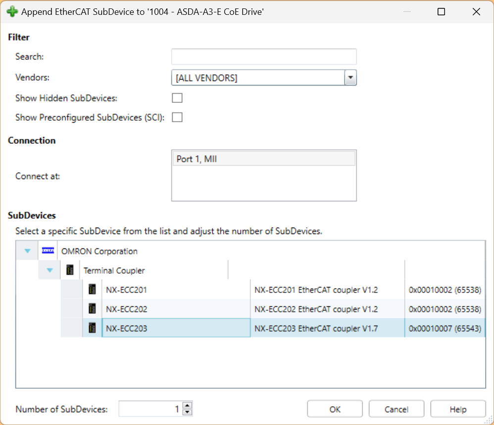
This is the Add Slave screen – use the Filter function to search for the Slave you need. In this example, let’s add OMRON’s NX-ECC203.
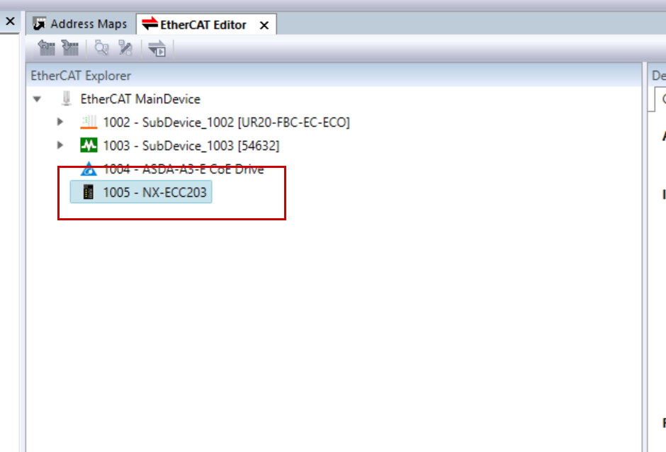
Done!NX-ECC203 has been added.
Append Module
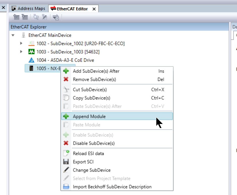
Right-click NX-ECC203>Append Module to add the IO module installed on the OMRON NX-ECC203.
This will display the Insert Sub module screen.
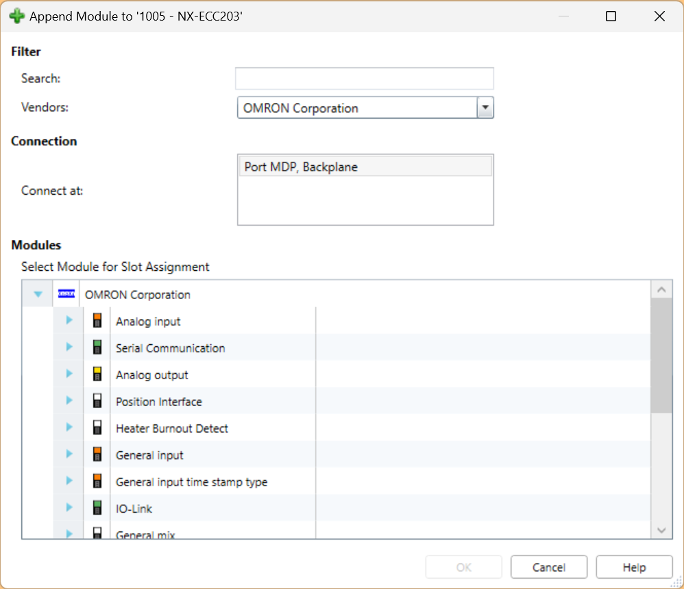
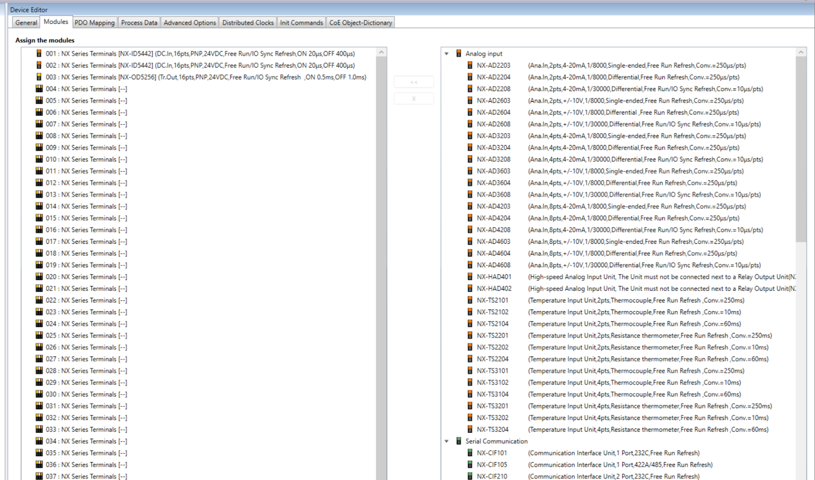
Use the Filter function to add the modules you need.
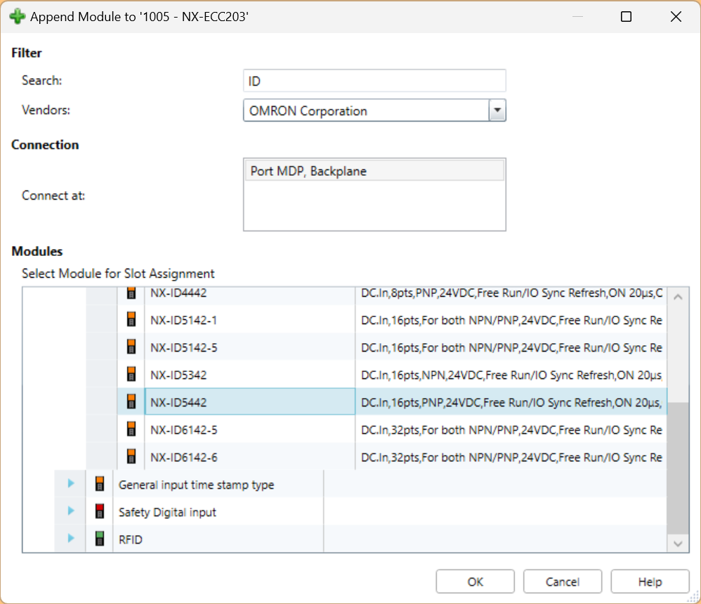
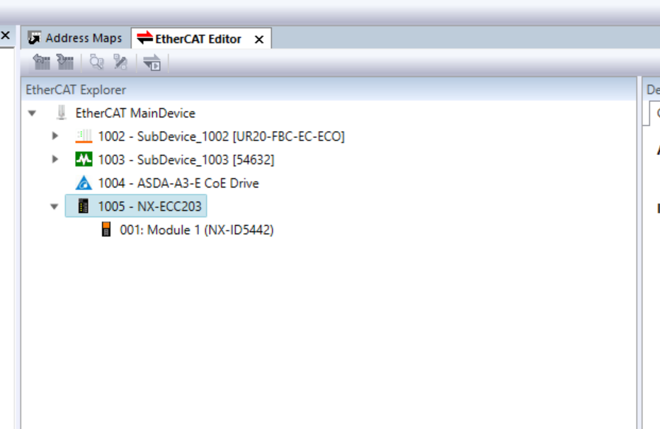
Done!The input module NX-ID5442 has been added.
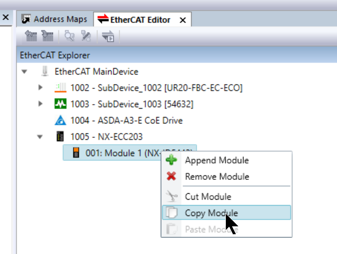
The same module can be added using the Copy function.
This is the configuration of the OMRON NX-ECC203.
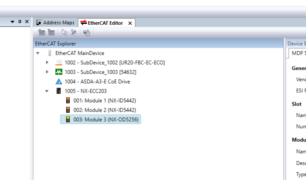
You can also change all Slot configurations directly in the Modules Tab.
Download
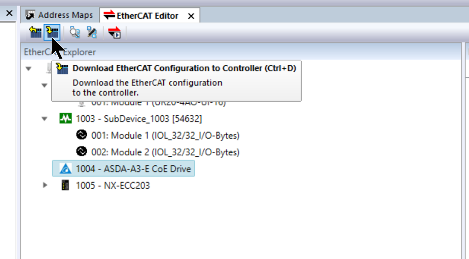
After you have completed setting up your EtherCAT network, click on Download EtherCAT Configuration to Controller and download the Hardware Cofiguration.
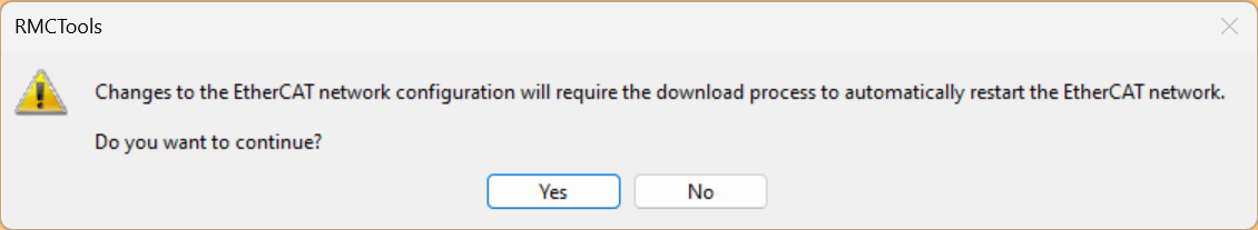
Proceed with Yes.
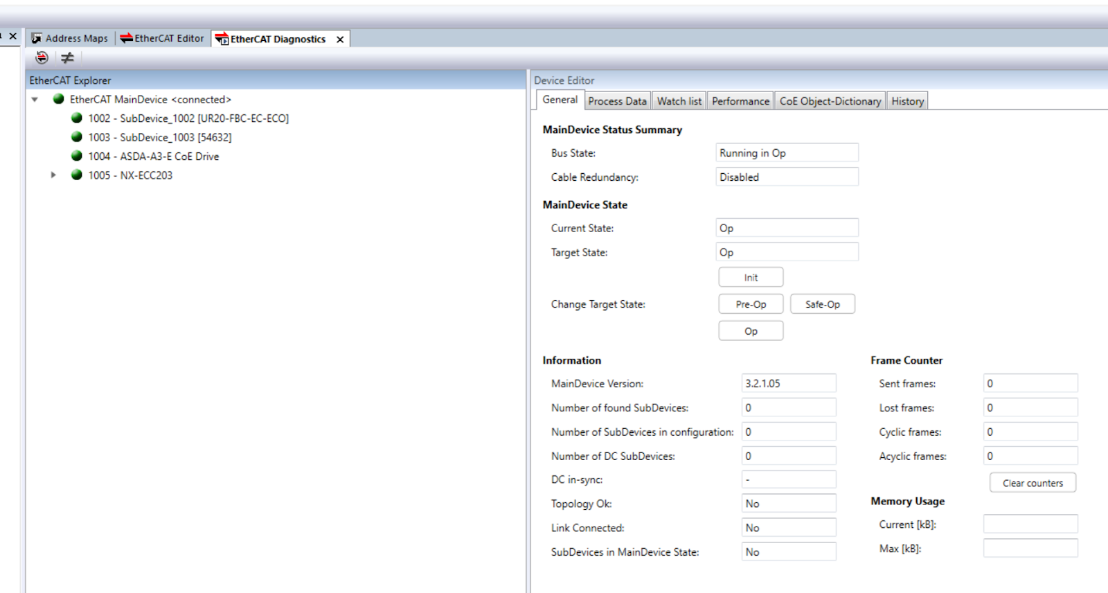
Start EtherCAT Diagnostics
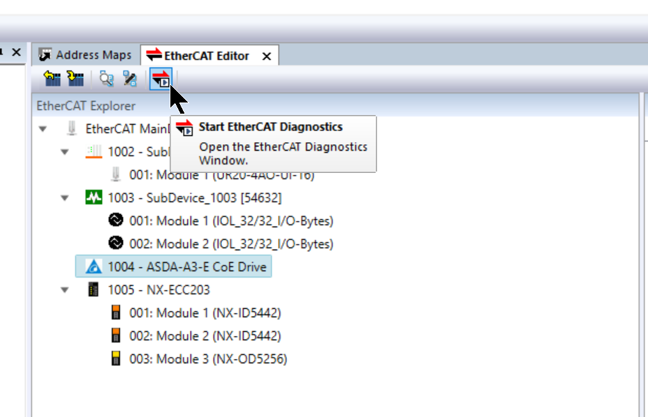
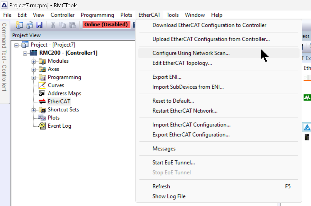
Click on Start EtherCAT Diagnostics to check the current EtherCAT network diagnostic information.
Configure Using Network Scan
RMC Tools also has the ability to Network Scan, which allows EtherCAT Slaves in the network to be uploaded to the projet at once.
Result
EtherCAT communication has started.
Configure Axis
This article will use servo motors from Delta, so Delta Motion’s RMC200 can also control Servo via EtherCAT.
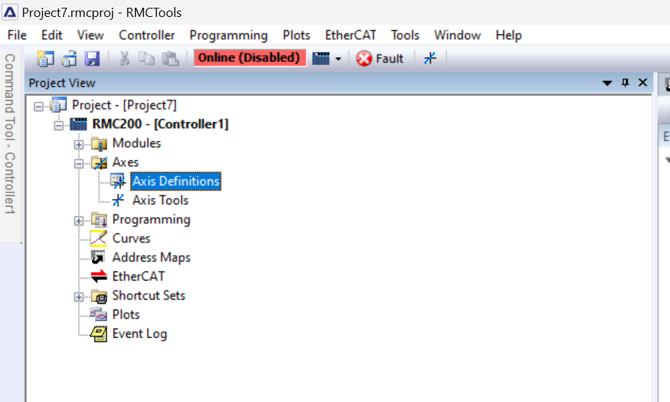
To add an EtherCAT Servo axis from RMC Tools, click Axes>Axis Definitions.
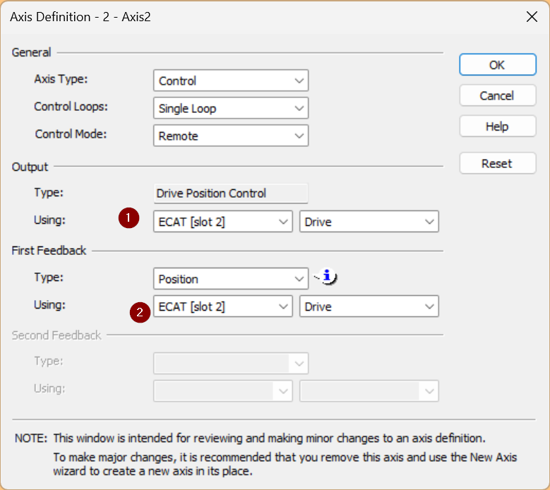
This is the RMC Tools axis settings screen, click New to add a new axis.
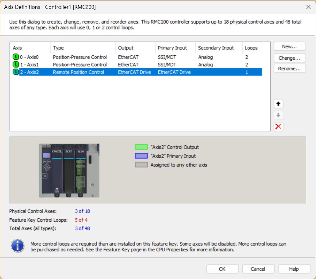
Set Control Mode to Remote and Output and First Feedback to ECAT [Slot 2].
Axis Parameters
The next step is to set the parameters for the EtherCAT axes you have just added.

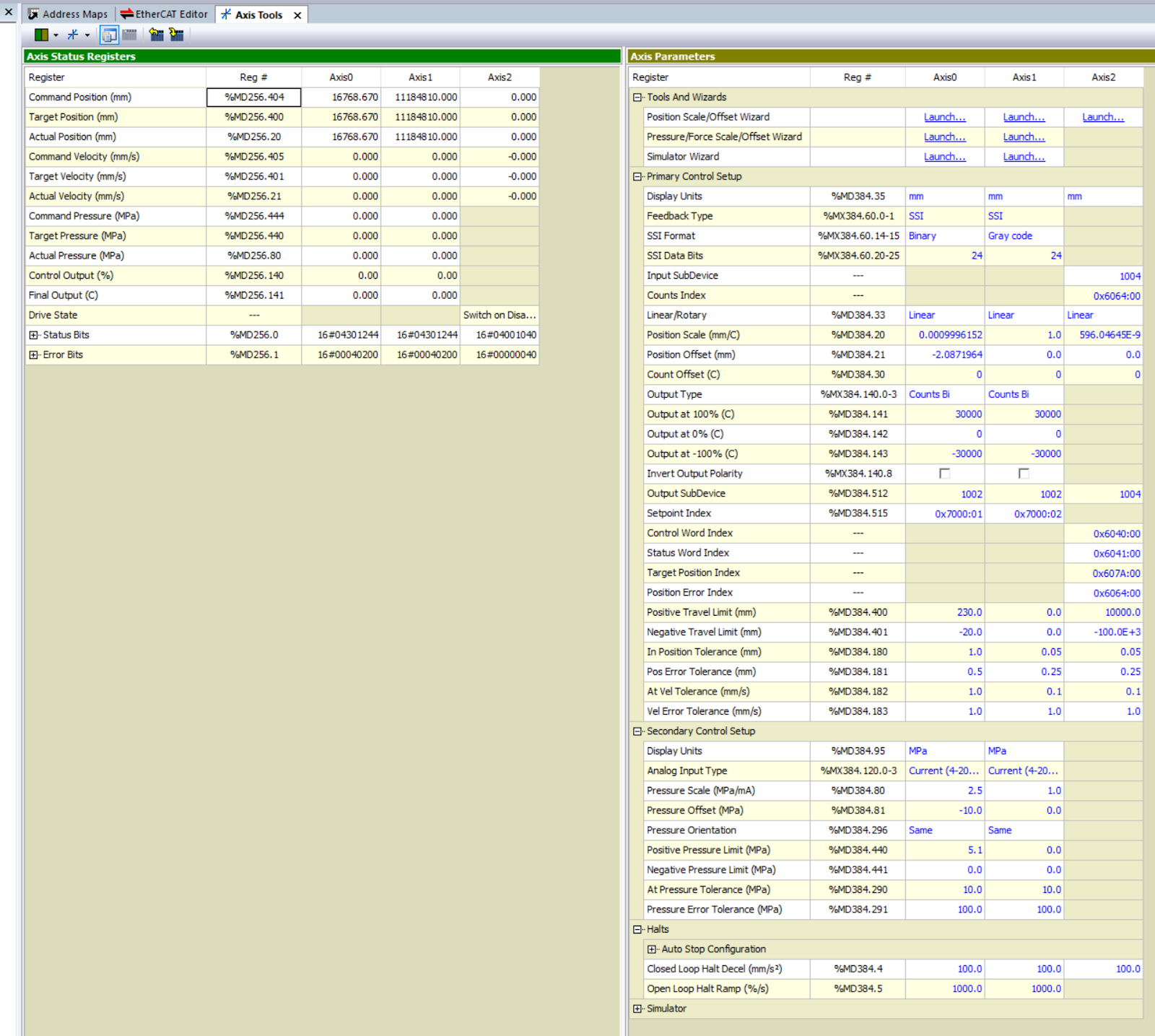
This is the parameterisation screen for all axes defined in RMC Tools.
Position Scale/Offset Wizard
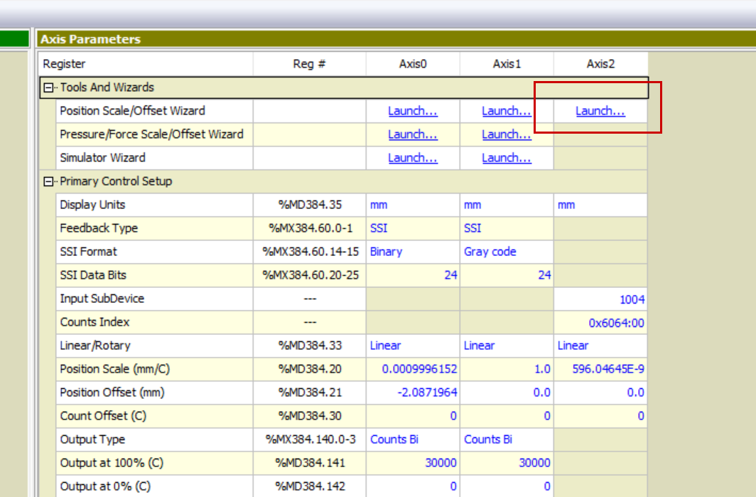
To set the Position Scale first, click Tools And Wizards>Axis2>Launch. Here you can set the resolution required for a single rotation.
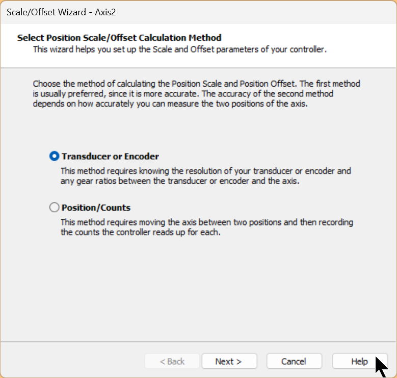
The method used in this case is the ‘Transducer or Encoder Method or Calibration Data’ setting.
This asks the user to provide information about the transducer, usually obtained from the datasheet, and is very accurate and configurable, but if no transducer data is available, this method cannot be used.
Select ‘Transducer or Encoder Method or Calibration Data’ and press Next> to continue.
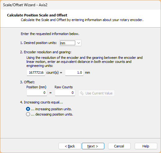
This is the resolution setting screen.
- This is the unit of movement of the mechanism.
- Set the number of pulses per rotation.
- Set if Offset is required.
- This is the direction of travel of the pulses.
As mentioned in Delta’s instruction manual, the ASDA-A3 has a 24-bit resolution and generates 16,777,216 pulses per motor revolution. Regardless of the encoder resolution (17-bit, 20-bit or 22-bit), the E-Gear ratio is set according to the 24-bit resolution of the ASDA-A3 servo drive. There is also a parameter called E-Gear ratio, which, when set to 1, generates 16,777,216 pulses per motor revolution.
In other words, it is currently set as 1 mm per 16777216 pulses (per revolution).
Next, proceed with Next>.
RMC Tools automatically calculates the parameters, check that the calculation results match those of the actual machine and proceed with Next>.
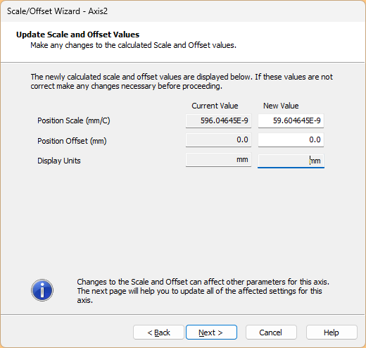
Check the current values and new parameters and proceed with Finish.
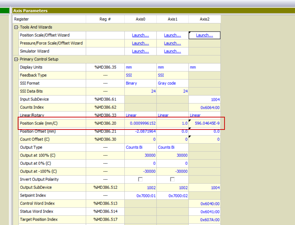
Done!Position Scale Scale Biow parameter values have been updated.
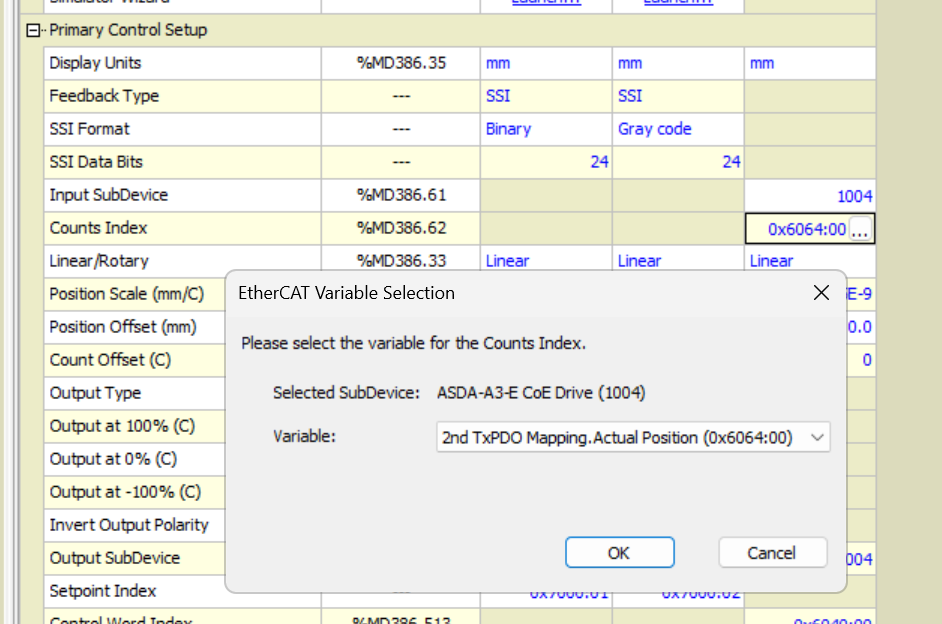
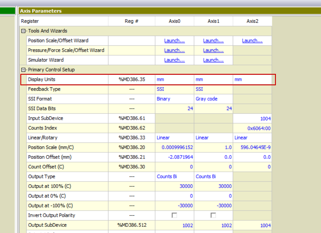
Count Index
The Counts Index axis parameter specifies the position of the EtherCAT data to be used as axis feedback. This is the position, velocity, pressure or force data required by the axis.
The data specified in the Counts Index is also the value in the Raw Counts Axis Status register, which is scaled and becomes the feedback value for the axis, e.g. Actual Position, Actual Force, etc.
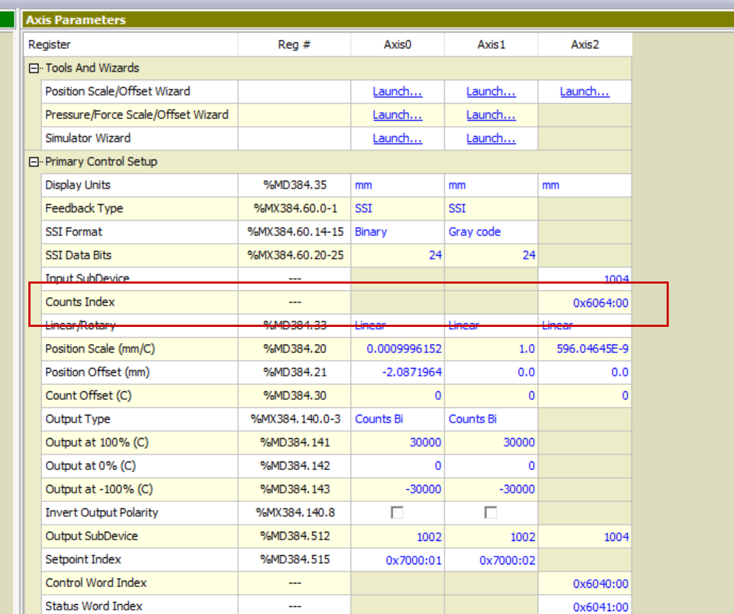
This time, set PDO 0x6064 for EtherCAT.
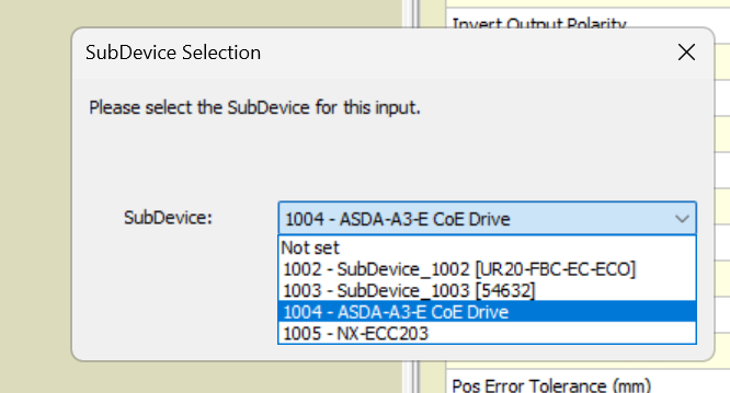
Input SubDevice
The Input SubDevice parameter can be set to select which EtherCAT SubDevice provides the axis feedback.
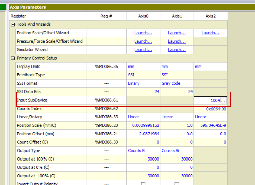
This time, we will control Delta’s ASDA-A3-E Servo via EtherCAT, so let’s set up the Servo Drive Slave that we have just added in the EtherCAT network.
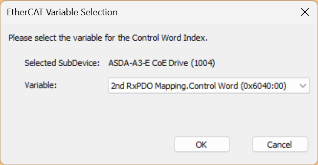
Control Word Index
The Control Word Index is applied by EtherCAT output types to drive or valve axes. These output types are defined in drive specification CiA402 and valve specification CiA408 and use control words and status words to control the drive or valve states.
These states are displayed in the axis status registers of the drive and valve states, but are separate from EtherCAT communication states such as the EtherCAT State Machine states Init, Pre-op and Op.
Also, the Control Word Index is normally 0x6040:00, but for multi-axis drives, the index is normally incremented by 0x800 for each axis. For example, the Control Word Index for the second axis of the drive (axis 1) is normally 0x6840:00.

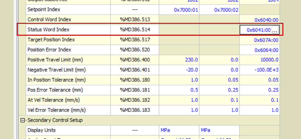
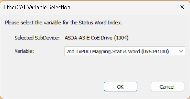
Status Word Index
The Status Word Index applies EtherCAT output types to the drive or valve axis. These output types are defined in drive specification CiA402 and valve specification CiA408 and use control words and status words to control the drive or valve status. These states are displayed in the axis status registers of the drive and valve states, but are separate from EtherCAT communication states such as the EtherCAT State Machine states Init, Pre-op and Op.
Also, the Status Word Index is normally 0x6041:00. For multi-axis drives, the index is normally incremented by 0x800 for each axis. For example, the Status Word Index for the second axis of the drive (axis 1) is normally 0x6841:00.
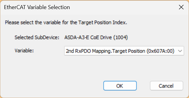
Target Position Index
This parameter is used to map the output of the RMC axis to the correct index in the drive. The target position index only applies to EtherCAT remotely controlled axes, the drive is in CSP mode and a position PID is performed in the drive. The output signal of the axis is the target position count which is continuously sent to the drive.
Also, the target position index is normally 0x607A:00. For multi-axis drives, the index is normally incremented by 0x800 for each axis. For example, the target position index for the second axis of the drive (axis 1) is normally 0x687A:00.

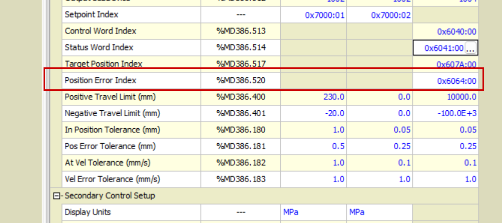
Position Error Index
This parameter is used to receive position follow errors from the EtherCAT drive in CSP mode and apply them to the position error axis status register.
The position error index only applies to EtherCAT drives in CSP mode: in CSP mode, the RMC continuously sends the target position to the drive, the drive performs the position PID calculation and the drive returns the actual position to the RMC. In EtherCAT networks Due to slight communication delays, the actual and target positions displayed in RMCTools are actually taken at different times.
This means that the difference between the Actual Position and Target Position reported by the RMC is not a true difference, and this is also true for the Position Error Axis Status register, and for the visual view of Actual Position and Target Position in the plot. The axis may show an error where the Actual Position and Target Position are not present, even though the axis is very well controlled.
To solve this problem, the tracking error can be read from the drive and assigned to the Position Error Axis Status register. The Position Error Axis Status register can then be included in the plot to show the true tracking error.
Typically, the Position Error Index is 0x60F4:00. For multi-axis drives, the index is normally incremented by 0x800 for each axis. For example, the position error index for the second axis of the drive (axis 1) is normally 0x687A:00.

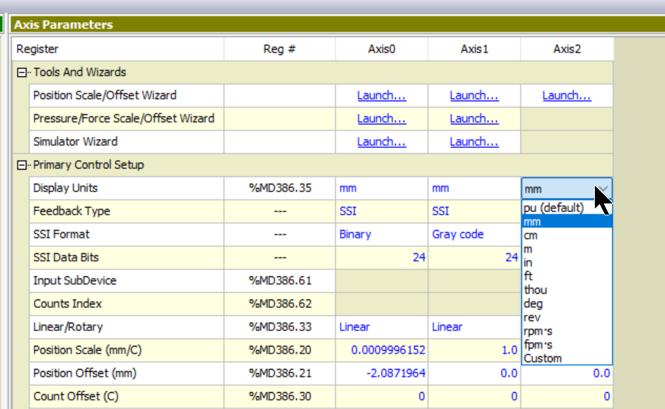
Display Unit
The Display Units axis parameter defines the feedback units displayed on that axis in RMCTools. Display units are for display purposes only and do not automatically scale feedback or convert between units.
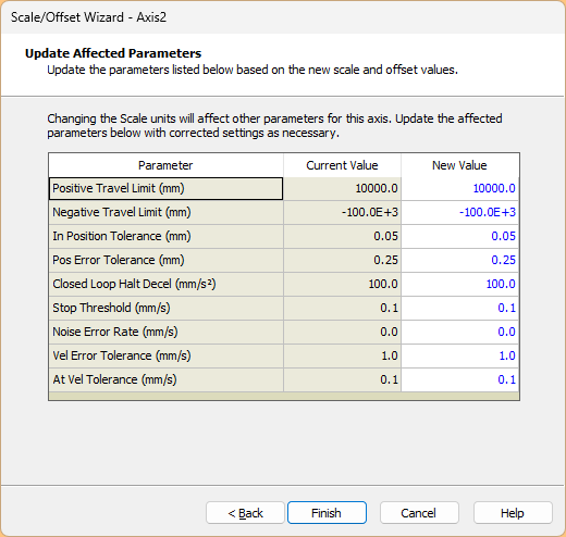
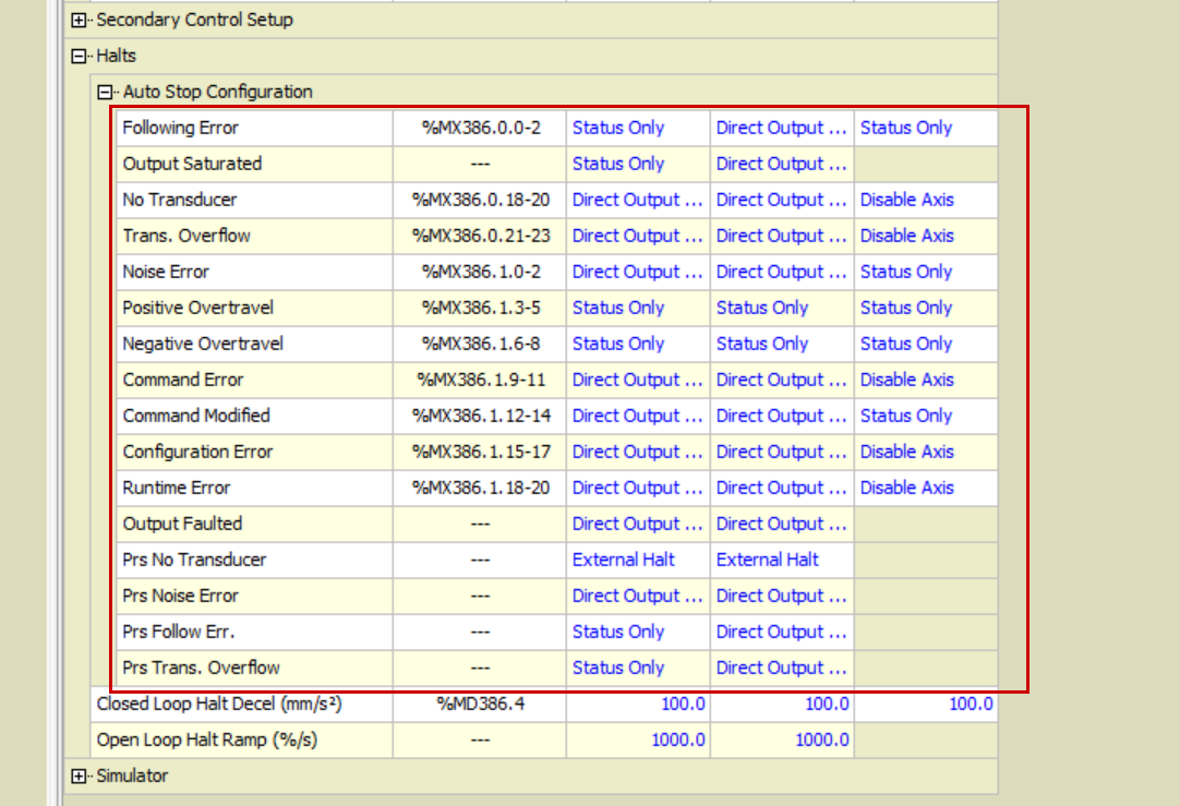
Auto Stop Configuration
Here are the error detection parameters when the axis operates. Set to match the actual application.
Download All to Controller
Finally, click on ‘Download All to Controller’ to download all configurations to the CPU.
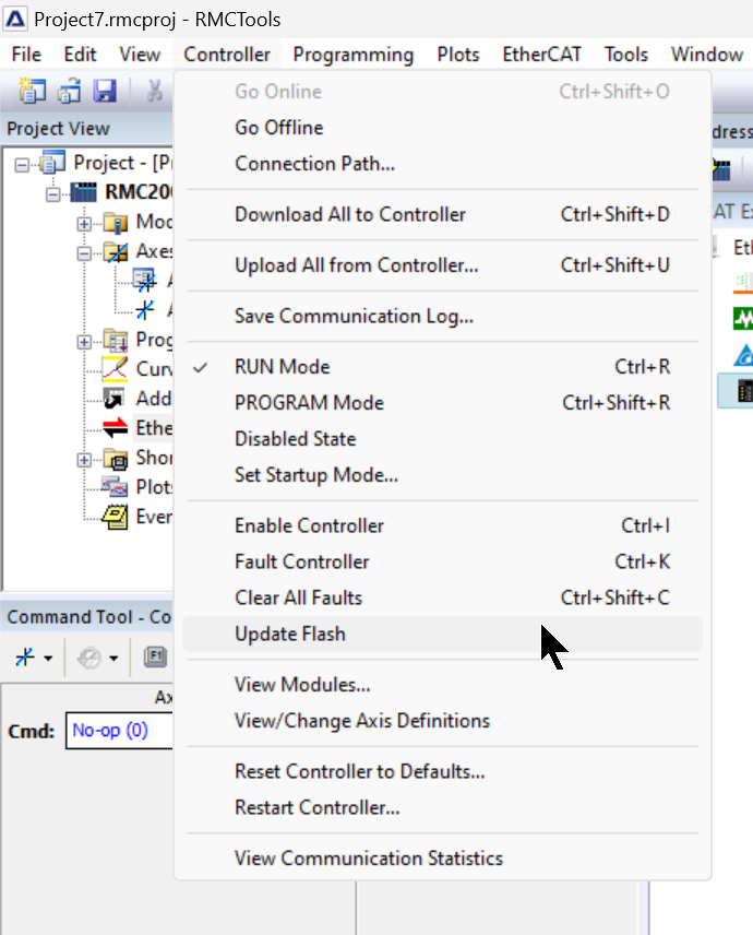
Update Flash
Go to Controller>Update Flash to write the data transferred to the CPU to ROM.
Result
This is the LED status when the ECAT module is communicating normally with the respective EtherCAT Slave.
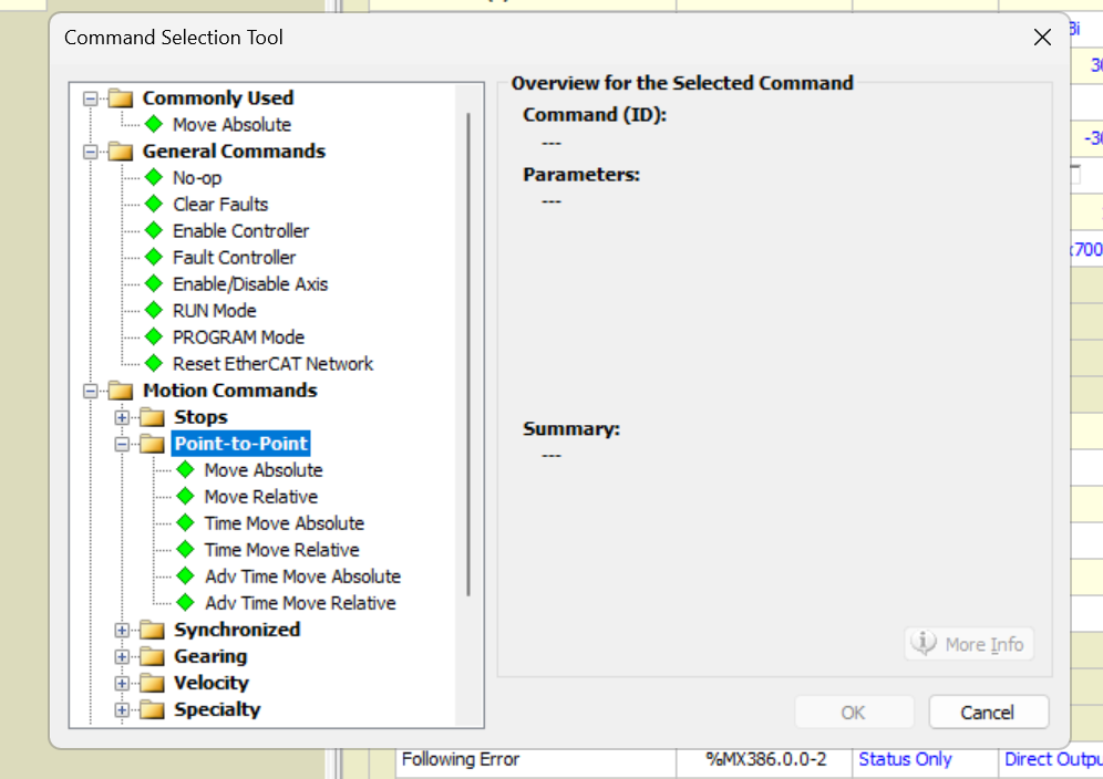
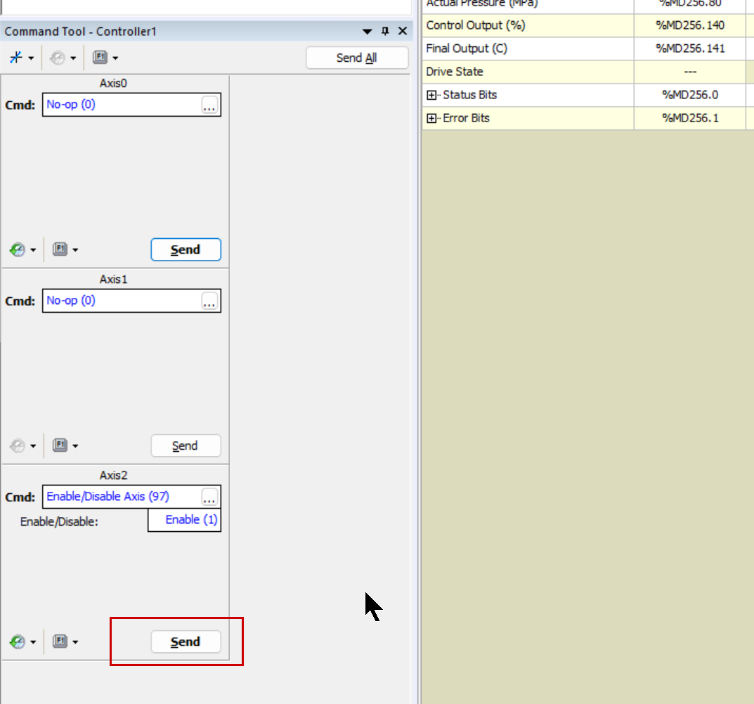
Finally, use the Command Tool to manipulate the Axis you have just added.
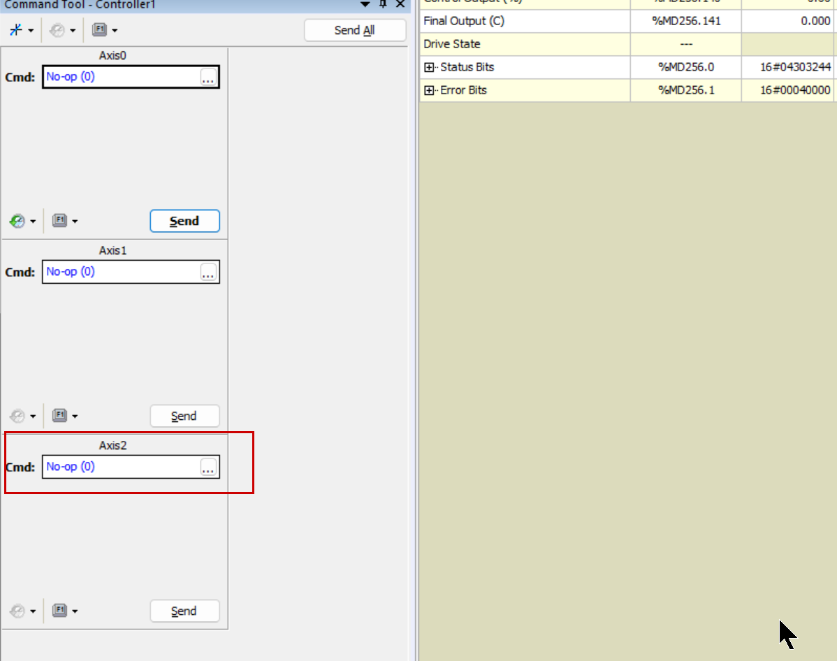
This is the screen where commands are issued to the axis from RMC Tools.
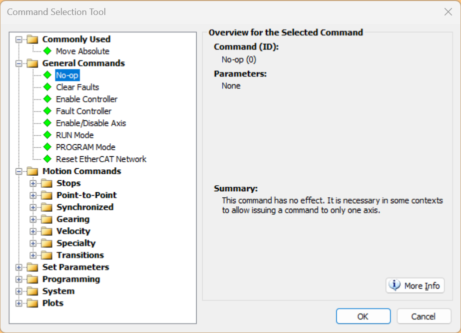
Enable/Disable Axis to enable the Delta Servo motor.
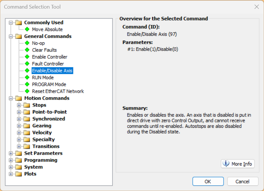
Set Enable in the Enable/Disable field.

Click on the Send button to issue the command.
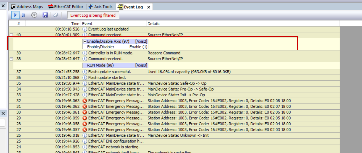
Done!The Event Log shows that the command has been received.
If you want to move the Servo motor, issue a Motion command at Motion Commands>Point-to-Point.