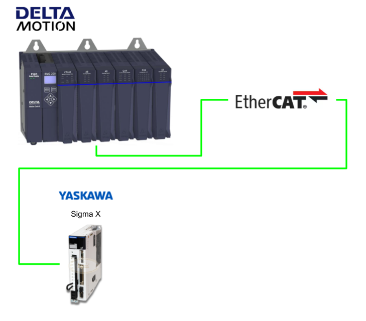
In this article, we will explain how to connect using EtherCAT using Delta Motion’s RMC200 and ECAT module, as well as how to create a program to control the axes and use the Default Axis variables.
Now, let’s enjoy FA.
DeltaMotionControl#Part06_Let’s use the ECAT module to link Yaskawa Electric Sigm-X and EtherCAT
Reference Link
http://soup01.com/en/category/yaskawa/
http://soup01.com/en/category/deltamotioncontrol_en/
Delta Motion ECATモジュールxYaskawa Electric Sigm-X
EtherCAT drives are generally easy to integrate with the RMC200, and we recommend drives that comply with the CiA 402 profile. The RMC200 supports CSP (Position), CSV (Velocity), and CST (Torque) modes, and necessary PDO settings are also pre-set.
Also, in the case of Yaskawa Electric,
- Be careful with the internal gear ratio setting (misconfiguration may cause confusion)
- In CSP mode, a dedicated tuning procedure is required to enable internal velocity feedforward
Implementation
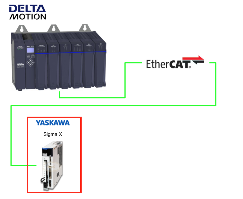
Sigm-X side
The Scaling settings on the Sigm-X side can be a bit complicated, so I will explain them again here. First, let’s look at an example.
1 rotation = 6mm
-
Ball screw lead: 6mm
-
Encoder: 26bit = 67,108,864 counts
-
Reference Unit = 0.001mm
Conversion flow
-
Moves 6mm per rotation → 6,000 units in 0.001mm units
-
A = 67108864
-
B = 6000
-
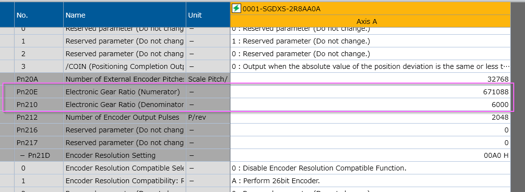
Without gear ratio consideration → Electronic Gear Ratio = 67108864 / 6000 × 1/64
-
Position User Unit = Numerator / Denominator = 1048576 / 6000
Let’s configure the settings in the figure below according to the previous calculation.
1 rotation = 10mm
-
Machine 1 rotation = 10 mm
-
User unit (Reference Unit) = 0.001 mm (= 1 μm)
-
→ Distance per rotation = 10 mm ÷ 0.001 mm = 10,000 units
This will be the travel distance per single rotation.
Conversion flow
Item | Value |
|---|---|
A (Encoder) | 67108864(26 bit) |
B (1 rotation = how many units) | 10000 |
Electronic Gear Ratio (B/A × 1/64) | 10000 / 67108864 × 1/64 |
Position User Unit |
Numerator = 1048576
|
Delta Motion RMC200 Side
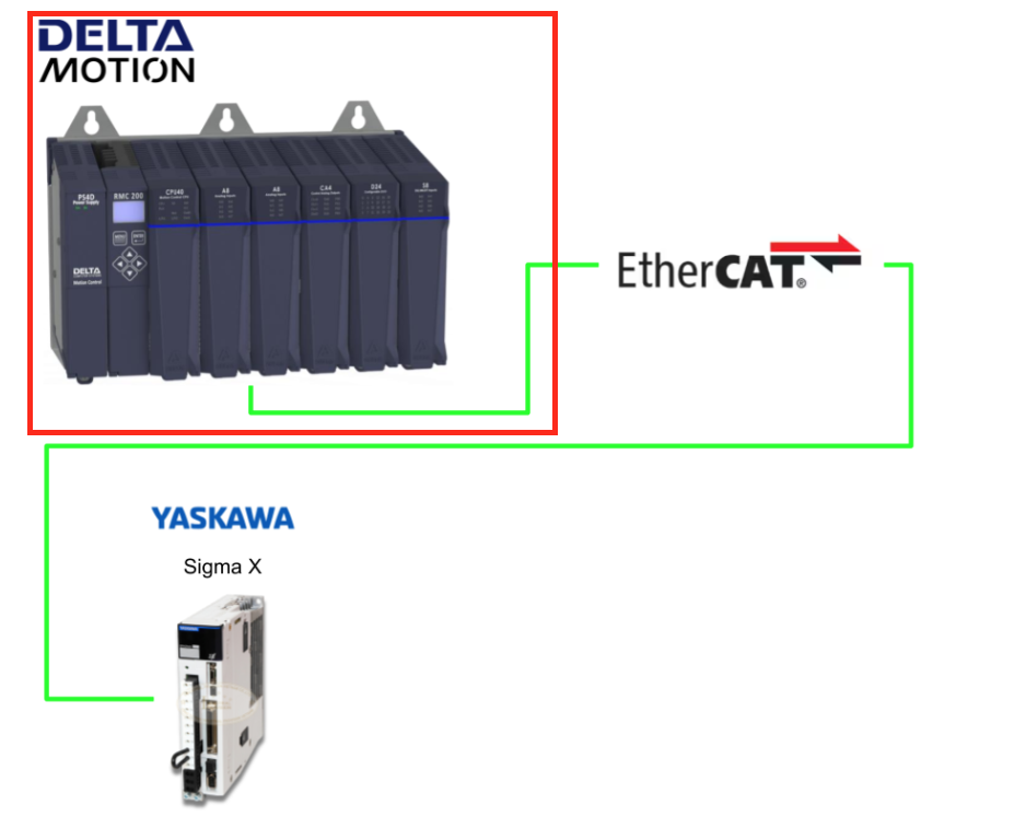
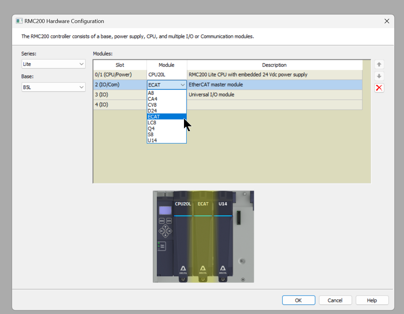
Add EtherCAT Module
First, please add the ECAT module to your RMC project.
Install ESI File
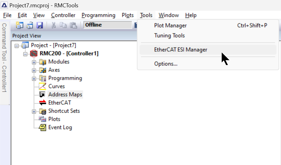
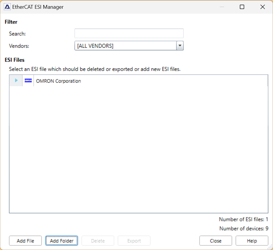
Next, click Tools > EtherCAT ESI Manager to install the EtherCAT ESI File.
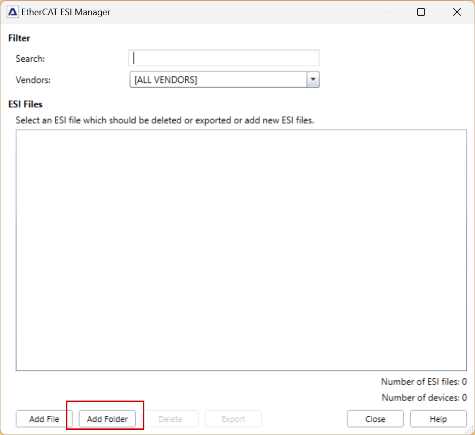
Click Add Folder.
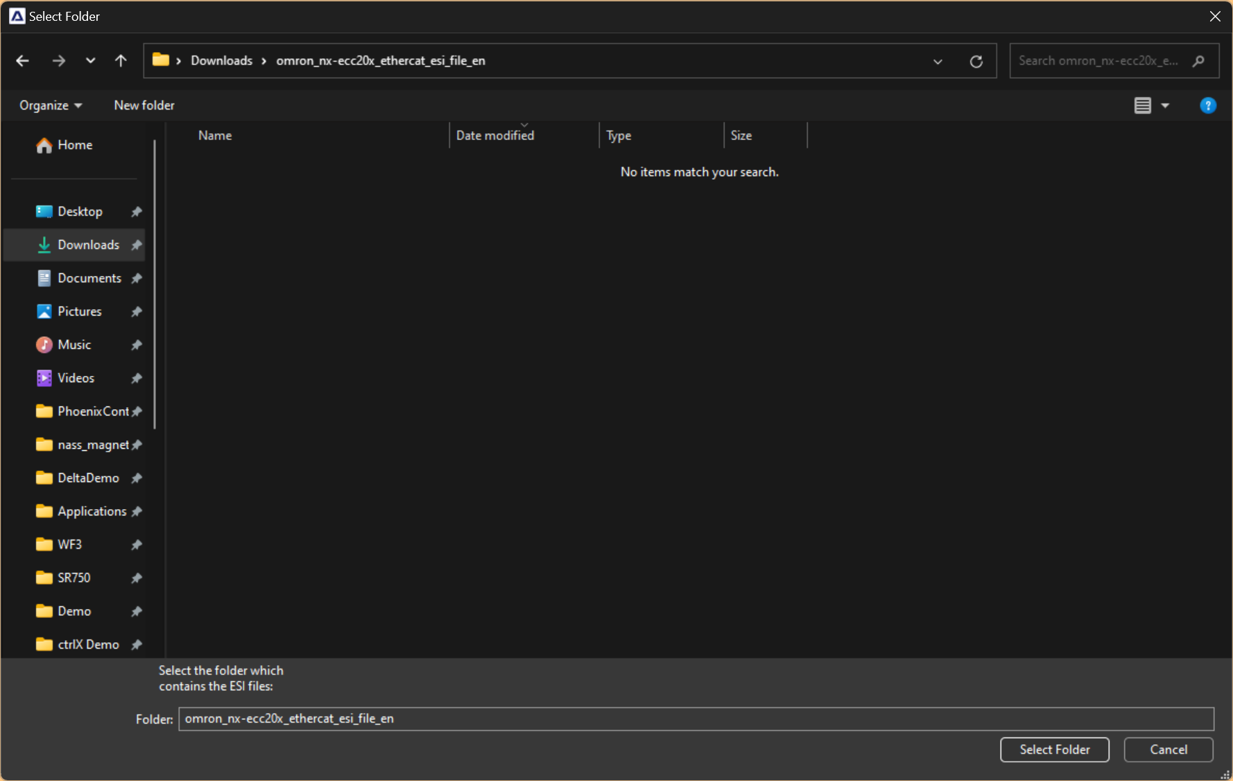
Import the ESI File downloaded from each manufacturer’s website.
Done! The ESI File has been imported.
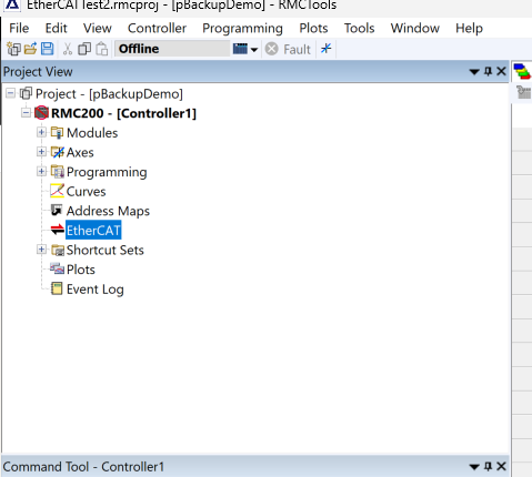
EtherCAT
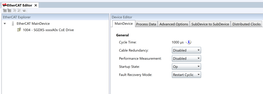
Next, build the EtherCAT network from the RMC tool.
This is the EtherCAT network construction screen of the RMC tool.
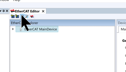
Scan
Click the Scan button shown below to search for EtherCAT slaves on the network.
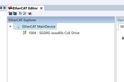
Done! We were able to find the Yaskawa Sigm-X Servo used in this article.
PDO Mapping
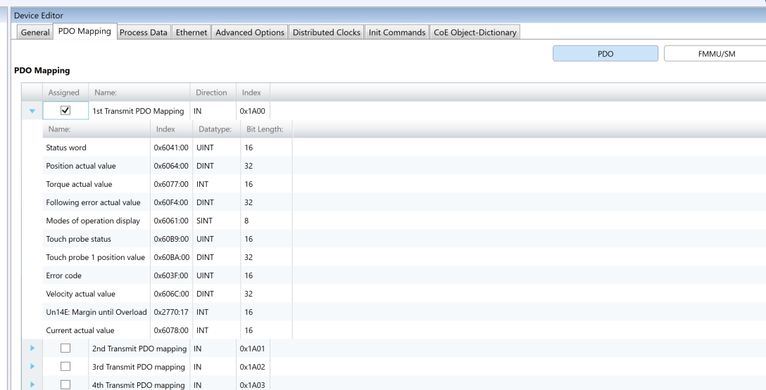
Next, please change the PDO Mapping of the Yaskawa Sigm-X according to your application. In this article, current velocity, error code, and current have also been added to the PDO Mapping.
Axis Definition
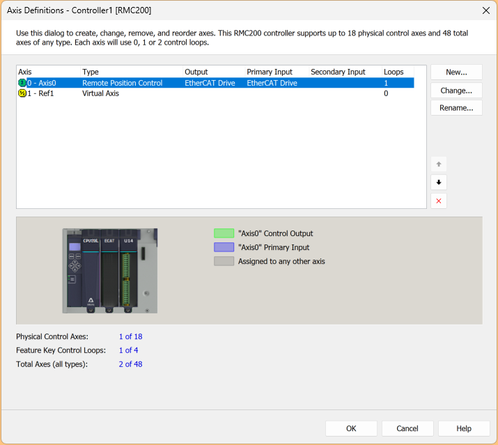
To use the Yaskawa Sigm-X on the RMC200, please add a remote axis in the Axis Definition.
Add Remote Axis
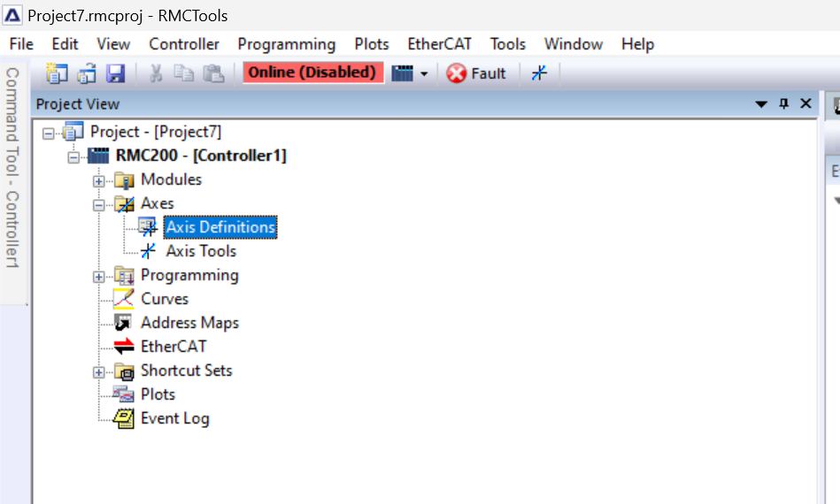
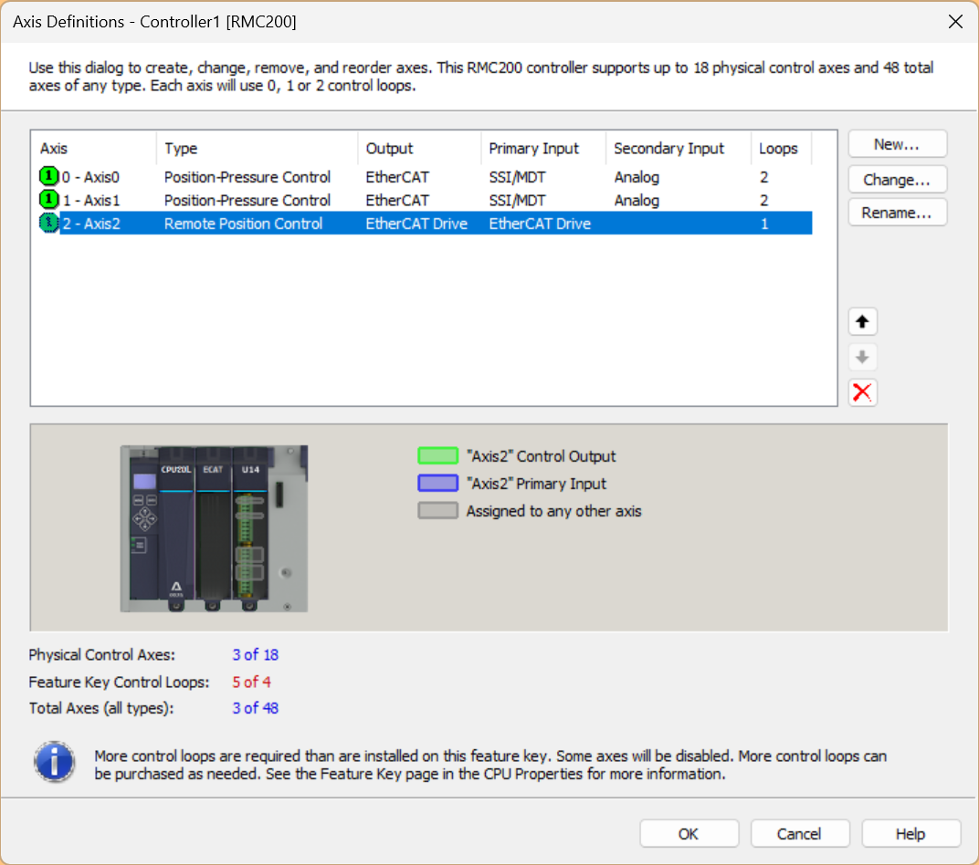
To add an EtherCAT Servo axis from RMC Tools, click Axes > Axis Definitions.
This is the axis setting screen of RMC Tools. Click New to add a new axis.
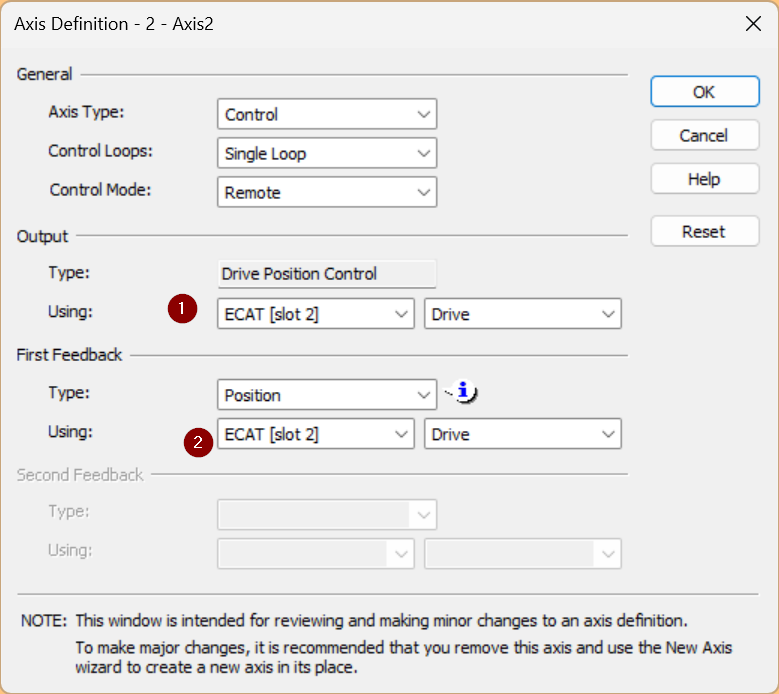
Set Control Mode to Remote, and set Output and First Feedback to ECAT[Slot 2].
Virtual Axis
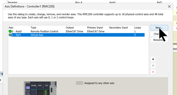
RMC200 also supports virtual axes; to add one, click the New button.
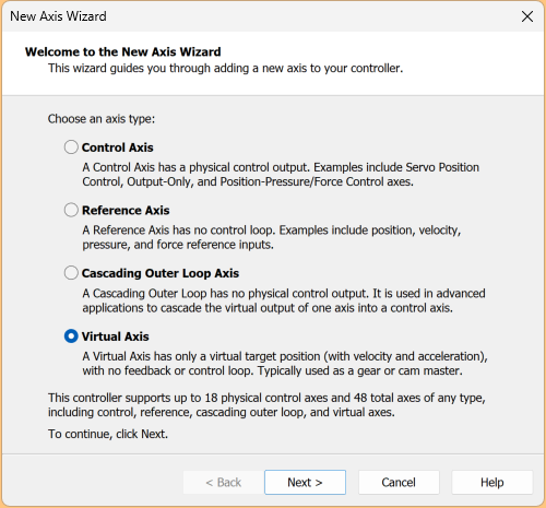
The axis addition screen will be displayed; select Virtual Axis and proceed with Next >.
Click Finish to add the virtual axis.
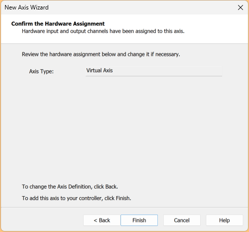
Done!
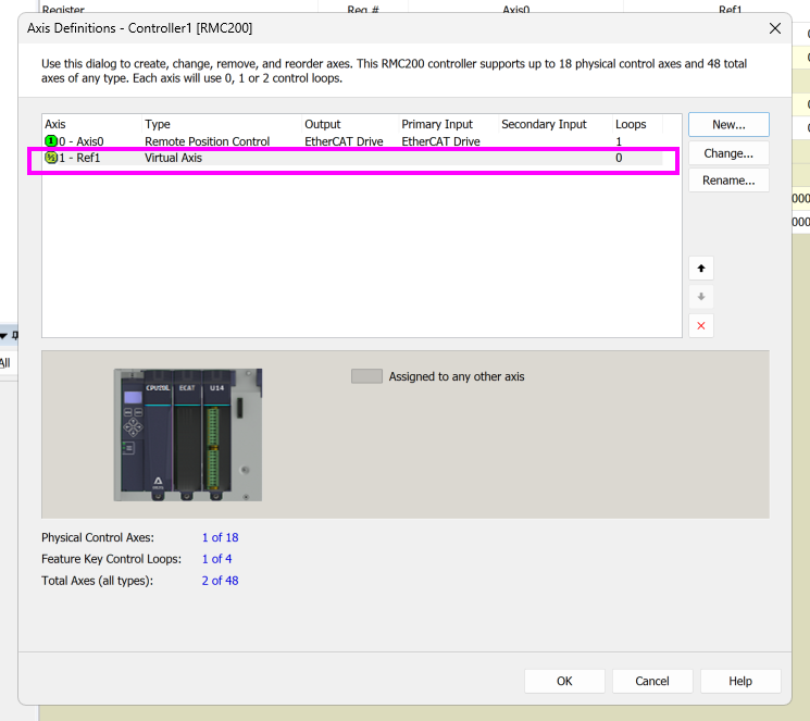
Parameters Configuration
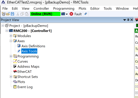
Now, to set the axis parameters for the Yaskawa Sigm-X, open Axis Tools.
This is the axis setting parameter screen of the RMC tool.
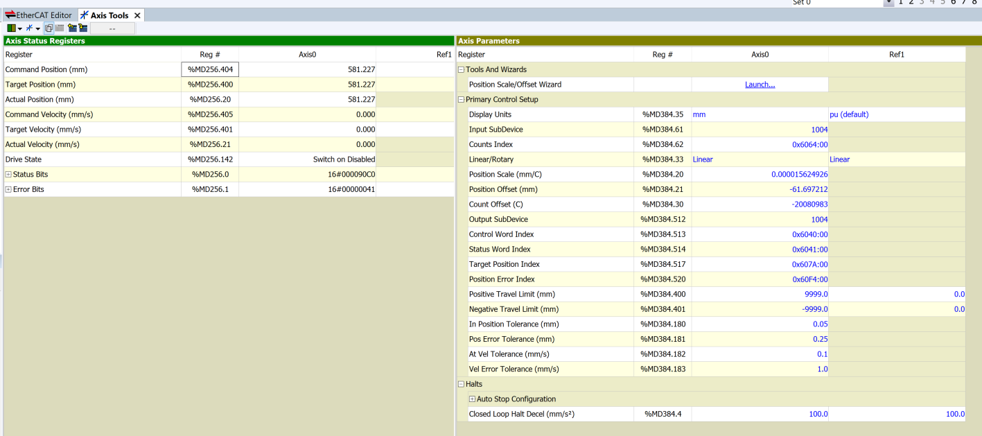
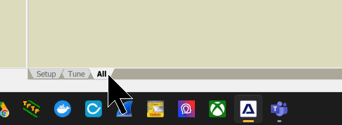
Open the All Tab at the bottom of the RMC tool.
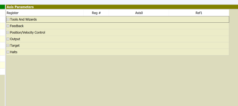
You will be able to display all parameters for all axes in the RMC tool.
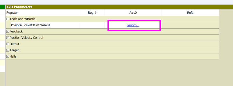
Position Scale
The first thing to set is Position Scale. This is the place to set the ratio between the travel amount of the Servo motor and the encoder.
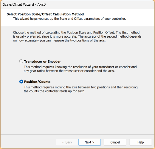
Select Position/Counts and proceed with Next >.
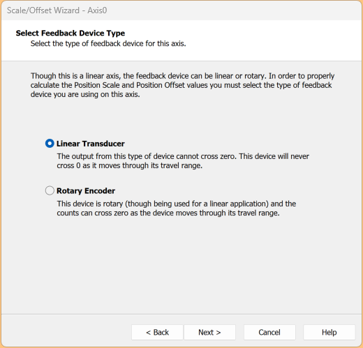
This time, select Linear Transducer and proceed with Next >.
Set Desired Position units to mm.
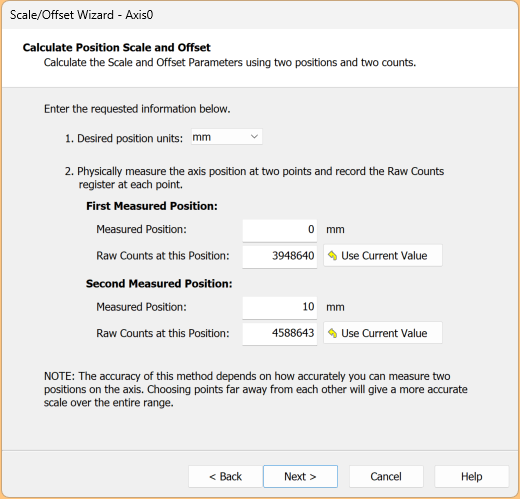
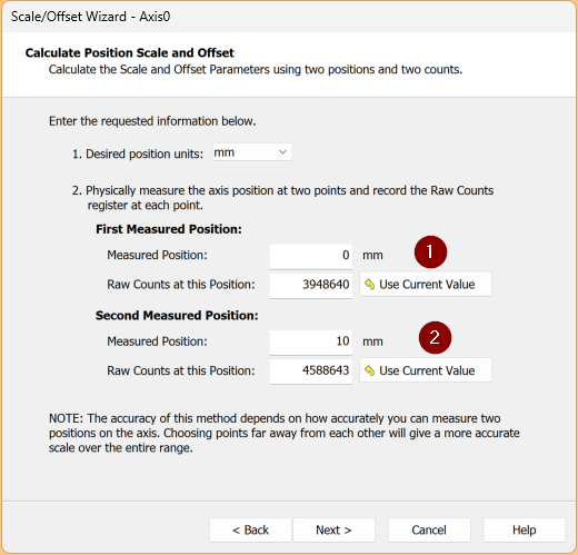
Next, use the Yaskawa tool to move to two locations. Then, for each location, click the “Use Current Value” button to record the corresponding Counts values, and the tool will calculate it automatically.
Proceed with Next >.
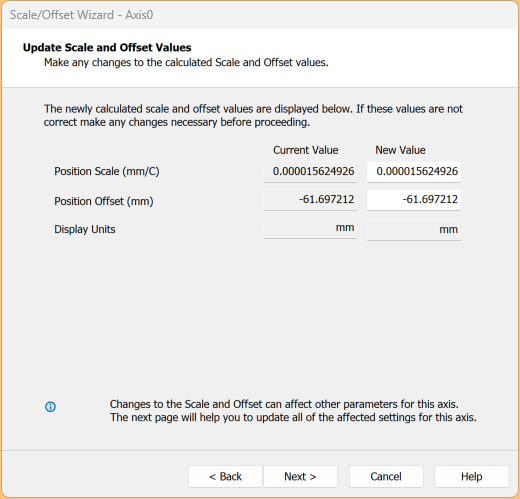
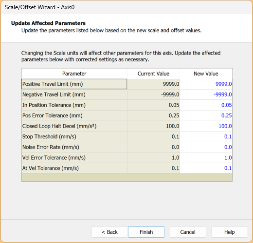
Click Finish to complete the settings.
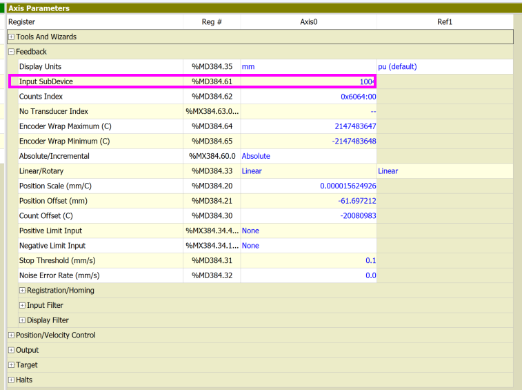
Input SubDevice
Next, configure the Input SubDevice.
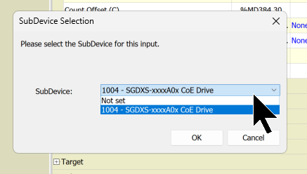
From the Drop-List, select the Yaskawa Servo connected via EtherCAT.
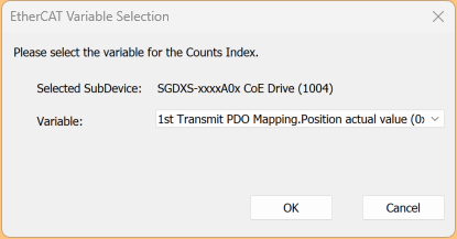
Counts Index
Set the Counts Index.
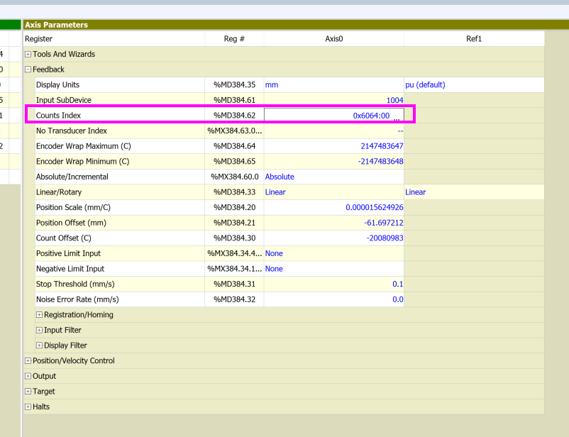
From the Drop-List, set the current position PDO to the Yaskawa Servo connected via EtherCAT.
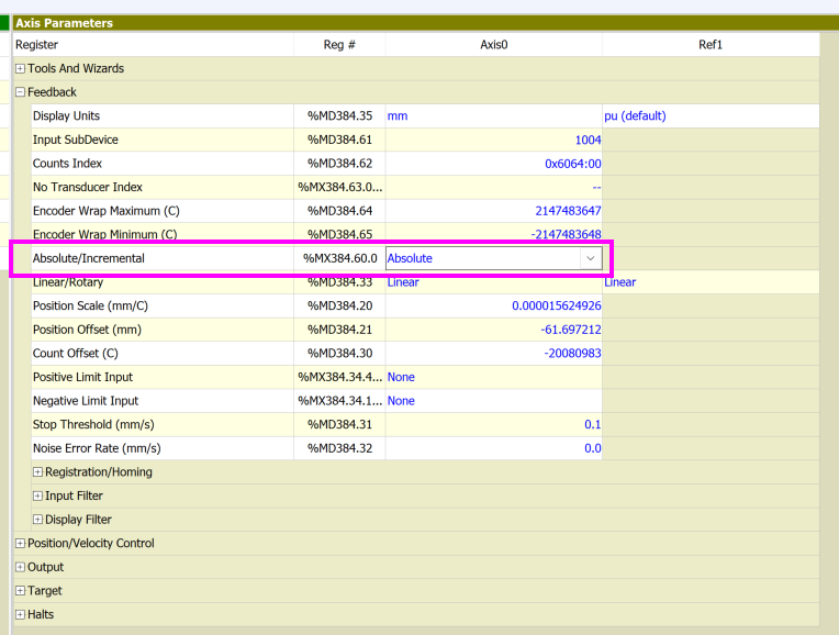
Absolute/Incremental
Set the Servo encoder type. The one used in this article is Incremental.
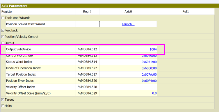
Output Subdevice
Set the Yaskawa Servo connected via EtherCAT from the Drop-List.
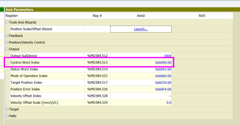
Contro Word Index
Set Control Word Index 0x6040 for the Yaskawa Servo connected via EtherCAT from the Drop-List.
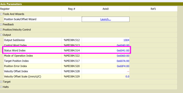
Status Word Index
Set Status Index 0x6041 for the Yaskawa Servo connected via EtherCAT from the Drop-List.
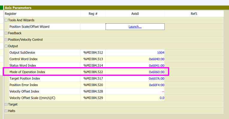
Mode of Operation Index
Set Mode Operation Index 0x6060 for the Yaskawa Servo connected via EtherCAT from the Drop-List.
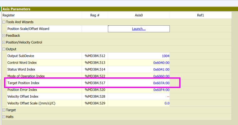
Target Position Index
Set Target Position Index 0x607A for the Yaskawa Servo connected via EtherCAT from the Drop-List.
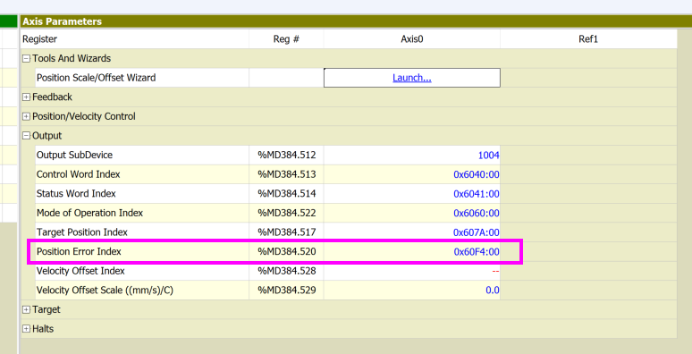
Position Error Index
Set Index 0x60F4 for the Yaskawa Servo connected via EtherCAT from the Drop-List.
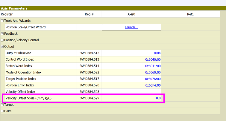
Velocity Offset Scale
In this article, Offset Scale will not be used, so be sure to set the parameters shown below to 0.
Variable Table
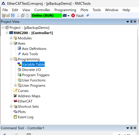
Define the variables for creating programs in RMC200.
Open Programming > Variable Table.
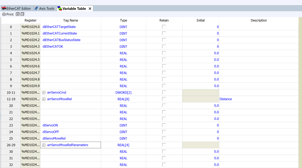
Several variables are defined in this article.
- Variables that can access the EtherCAT state
- Commands sent to each Servo
- A group of parameters required when sending commands
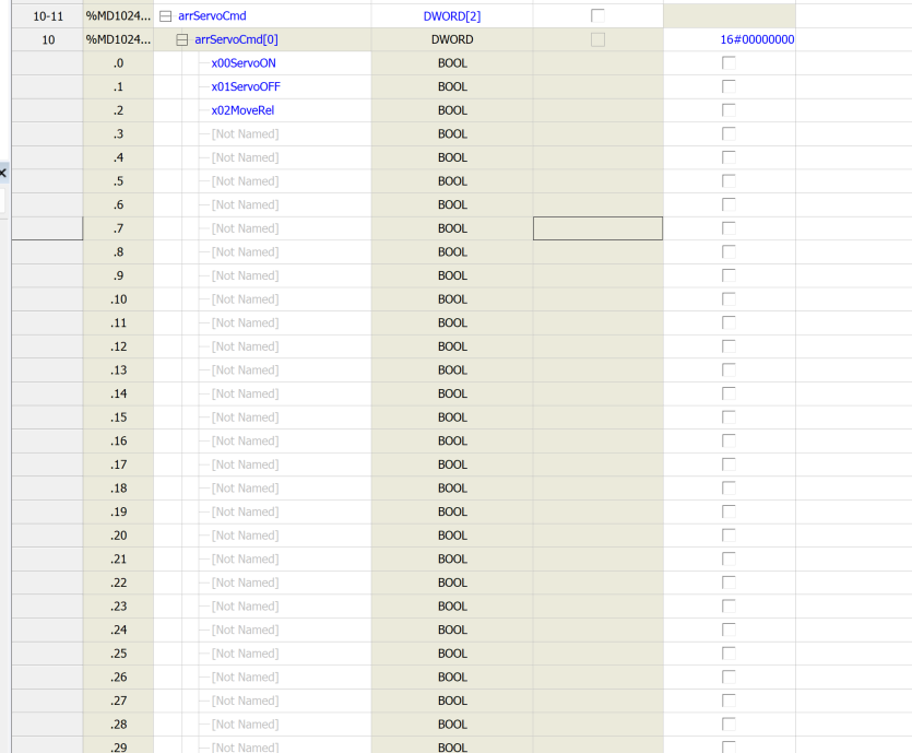
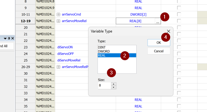
The RMC tool also supports array definitions. Individual comments are also possible for each Element of the array.
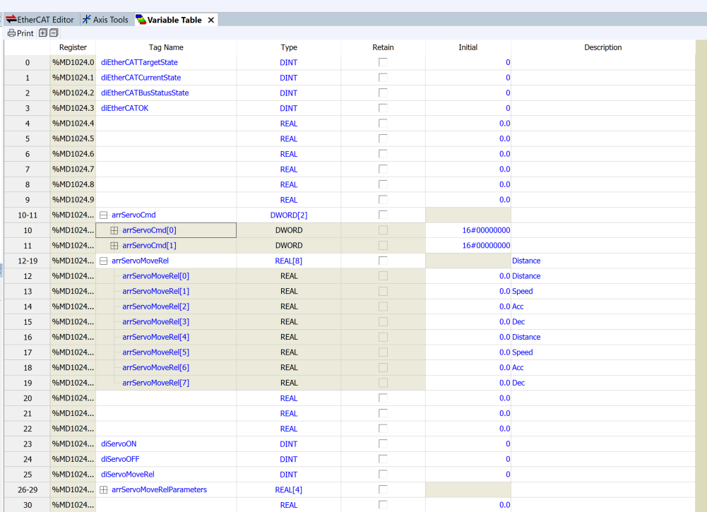
Furthermore, when a DWORD variable is defined, individual access and comment settings are possible for the 32 bits of the corresponding variable.
To define an array, simply set the length of the array in the Size column of the Variable Type screen.
Program
Next, create the program.
OB1
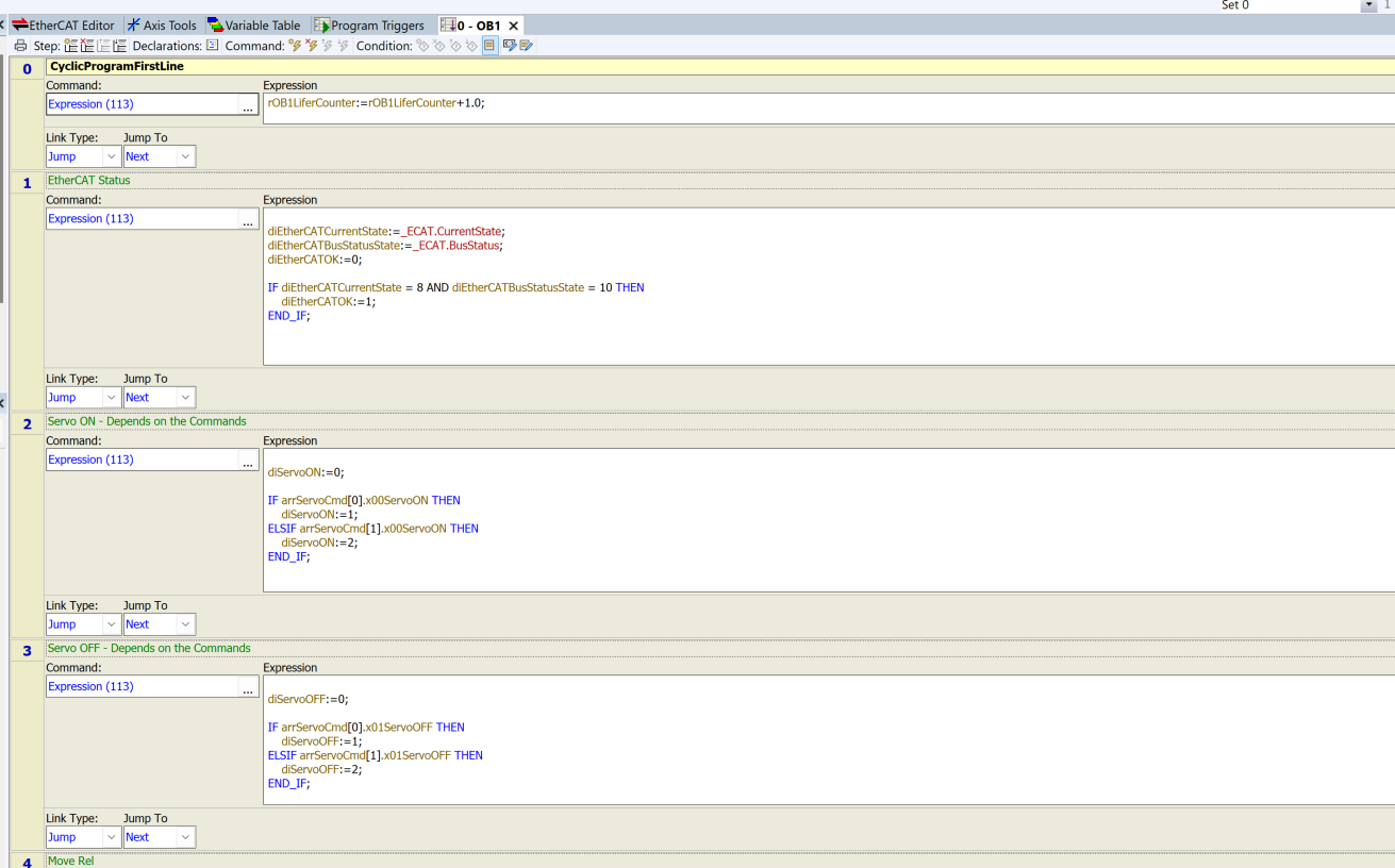
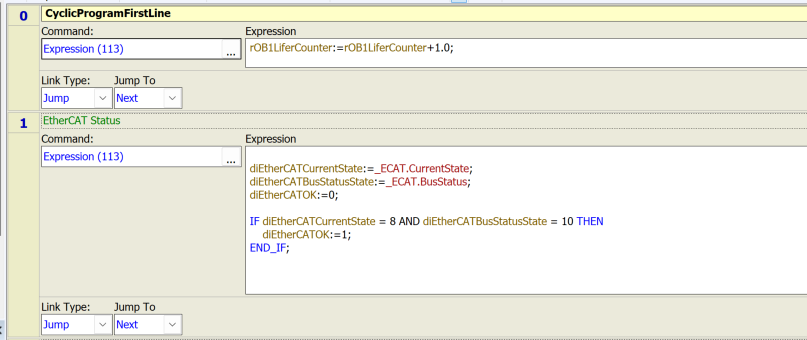
OB1 is a program that executes periodically to check the EtherCAT status and receive axis commands.
Network0・Network1
Network0 is the Life Counter, which allows you to check when the task is currently running normally.
Network1 constantly monitors the status of the EtherCAT network and writes 1 to dEtherCAT if it is OK.
Network2・Network3
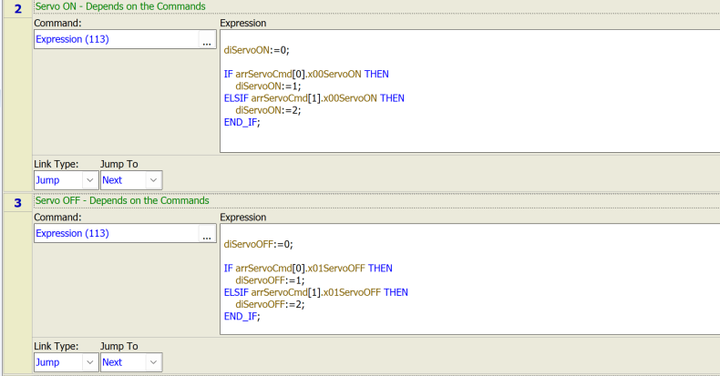
Network2 receives the Servo ON command.
For axis 1, diServoON=1, and for axis 2, diServoON=2.
Network3 receives the Servo OFF command.
For axis 1, diServoOFF=1, and for axis 2, diServoOFF=2.
These two registers will be used in the “Default Axis” utilized later.
Network4・Network5
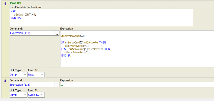
Network4 receives the relative positioning command.
For axis 1, diServoMovRel=1, and for axis 2, diServoMoveRel=2.
OB101
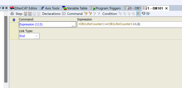
OB101 is a program that runs only once when the RMC200 enters RUN mode.
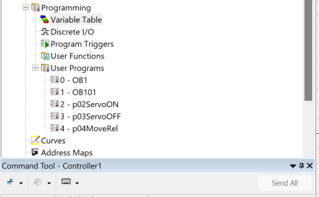
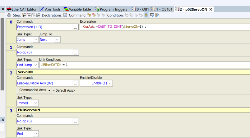
p02ServoON
This is the axis Servo ON program. The flow is as follows:
- Network0: Receive the axis number to be Servo ON and transfer the Default Axis value.
- Network1: If the EtherCAT status is OK, perform Servo ON; if NG, jump directly to Network3.
- Network2: Issue the Servo ON command.
- Network3: END.
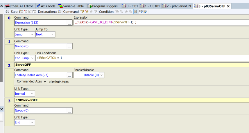
p03ServoOFF
This is the axis Servo OFF program. The flow is as follows:
- Network0: Receive the axis number to be Servo OFF and transfer the Default Axis value.
- Network1: If the EtherCAT status is OK, perform Servo OFF; if NG, jump directly to Network3.
- Network2: Issue the Servo OFF command.
- Network3: END.
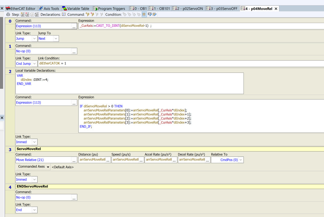
p04MotorRel
This is a program that issues a relative positioning command for the axis Servo. The flow is as follows:
- Network0: Receive the axis number to be moved and transfer the Default Axis value.
- Network1: If the EtherCAT status is OK, transfer parameters; if NG, jump directly to Network4.
- Network2: Program to transfer parameters.
- Network3: Issue the relative positioning command.
- Network4: END.
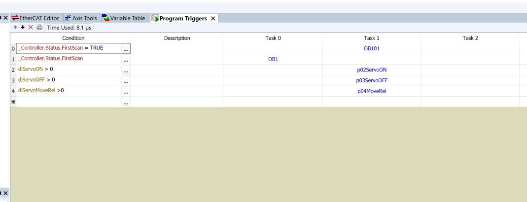
Program Trigger
Finally, define the Program Trigger.
- OB101 is a First SCAN Trigger and will not execute again once completed.
- OB1 is a First SCAN Trigger and will loop continuously after that.
- The SERVO ON/SERVO OFF/SERVO relative positioning programs start depending on the state of the variables.
Result
Please check the operation from this video.