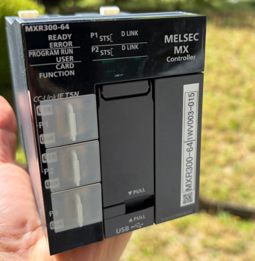
This is a new article series where we will perform various verifications using Mitsubishi Electric’s latest MXR controller. In the second part, we will build Simple CPU Communication.
- Mitsubishi Electric MXR300-64
- Weidmuller UR20-FBC-CC-TSN
- Mitsubishi Electric NZ2GN2S1-32D
- Mitsubishi Electric R00CPU
- Mitsubishi Electric RJ51AW12AL
- Anywire BL296PB-16F-V50
- Anywire BL296PB-08F-4-20
- Anywire BS-H0317-1K
Now, let’s enjoy FA!
Reference Link
http://soup01.com/en/category/mitsubishi-en/mxr-en/
SIMPLE CPU COMMUNICATION?
This function enables data communication between modules equipped with an Ethernet port and communication target devices. By connecting to the communication target device using the Ethernet port, data communication can be performed between the specified devices at the specified timing. You can build a communication system without creating a program by simply setting parameters in GX Works3. Furthermore, by using modules equipped with Ethernet ports to collect data from existing devices, it is possible to realize IoT utilizing existing equipment.
.
Implementation
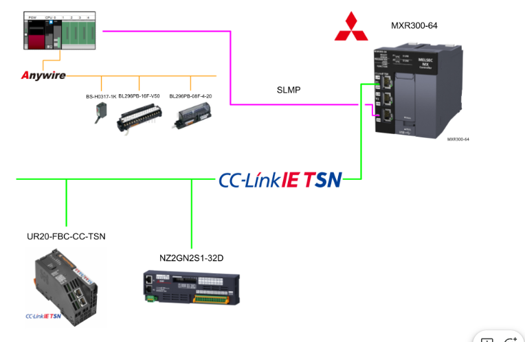
This is the structure of this article.
GXWORKS3 Version
This is my GXWORKS3 version for this time.

IQ-R Side
First, we will configure the Mitsubishi IQ-R CPU side.
IP Setting
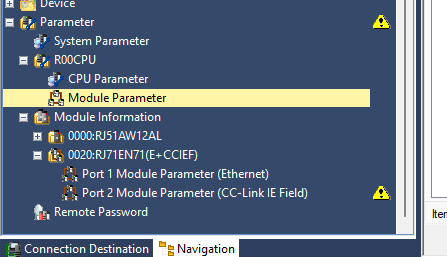
To set the IP address of the IQ-R CPU’s built-in Ethernet port, click R00CPU Module Parameter.
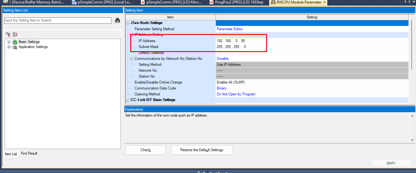
Set the IP address according to the network.
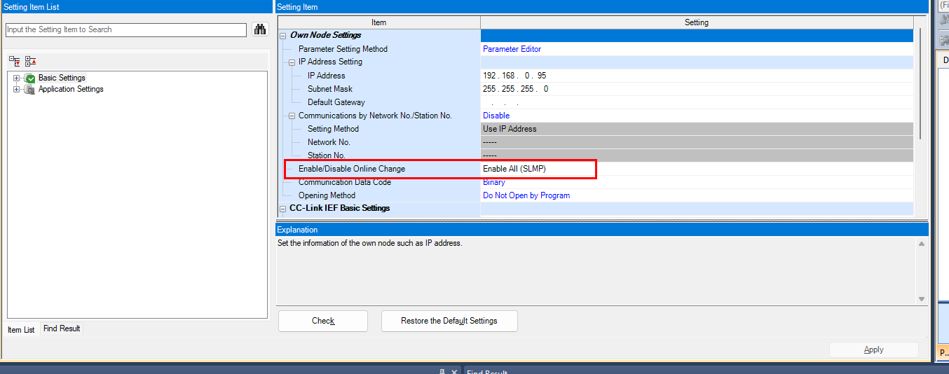
Enable SLMP
Next, enable the setting in the red frame in the figure below.
RJ71EN71 Setting
Finally, we configure the RJ71EN71.
IP Setting
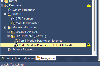
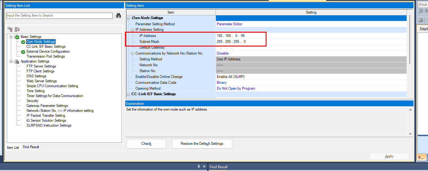
Click Module Information RJ71EN71 Port2 Module Parameter.
Set the IP address in Basic Setting Own Node Setting according to the network.
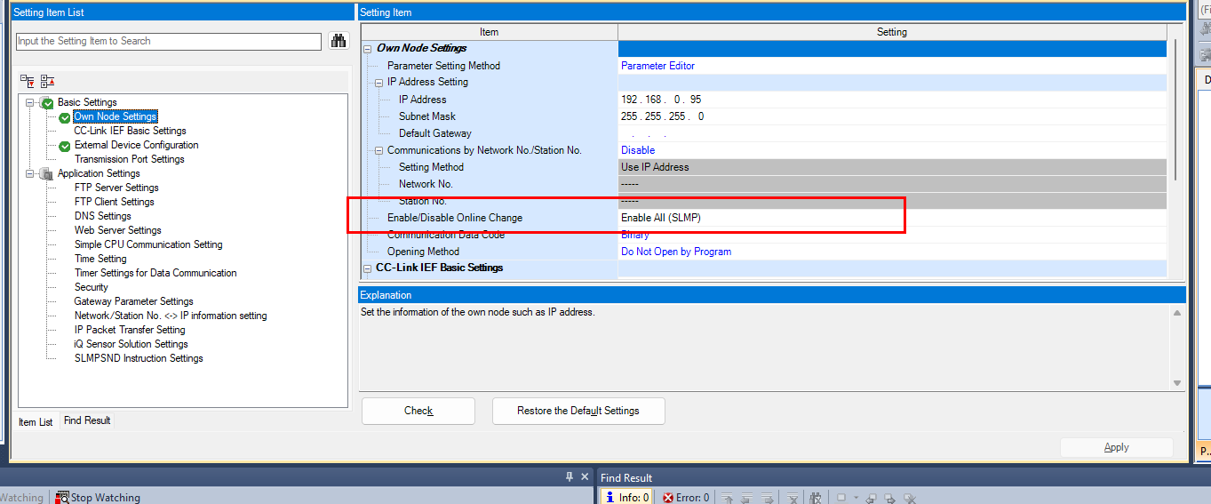
Enable SLMP
Next, enable the setting in the red frame in the figure below.
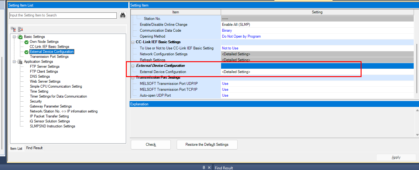
External Device Configuration
Now we will set up the external connection devices.
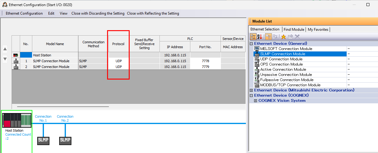
Add Ethernet Device SLMP Connection.
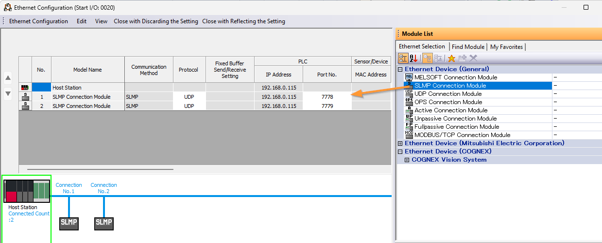
Next, set the Protocol to UDP.
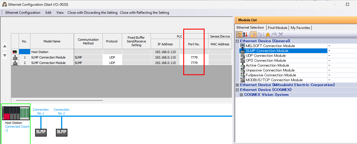
Set the Port number.
Program
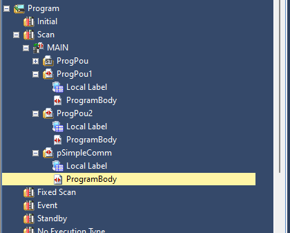
Next, we will create the communication test program for the IQ-R side.
Rung1
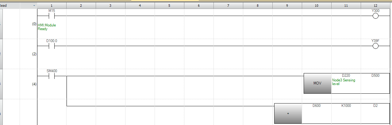
This is a simple 1-contact, 1-coil circuit that turns ON the output relay Y300 when M15 is ON.

Rung2
This is a simple 1-contact, 1-coil circuit that turns ON the output relay Y39F when D100.0 is ON.

Rung3-4
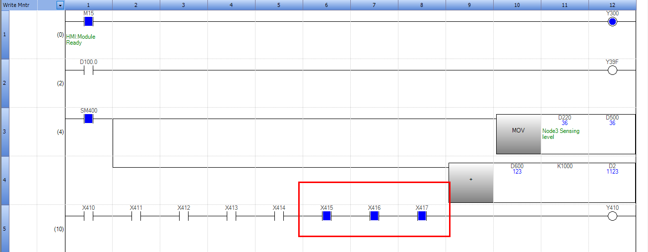
In Rungs 3 and 4, the transferred sensing level value from D220 is transferred to D600 and simultaneously multiplied by 1000 and stored in D2.

Rung5
Rung 5 is a circuit that turns ON the output relay Y410 when all 8 points from X410 to X417 are ON.

Download
Next, download the project to the IQ-R and restart the CPU.
MXR Controller Side
Next, we will configure the MXR300-64 side.
IP Setting
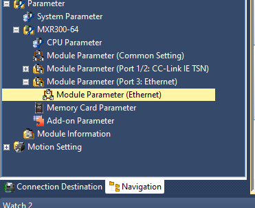
First, set the IP address of the MXR300-64. Click Module Parameter Module Parameter(Ethernet).
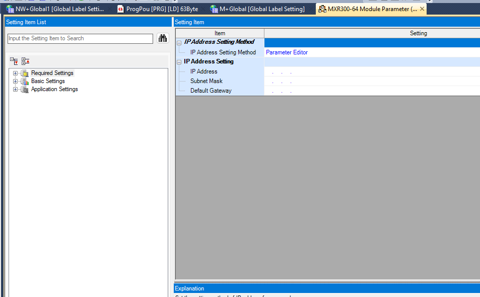
This is the Ethernet setting screen.
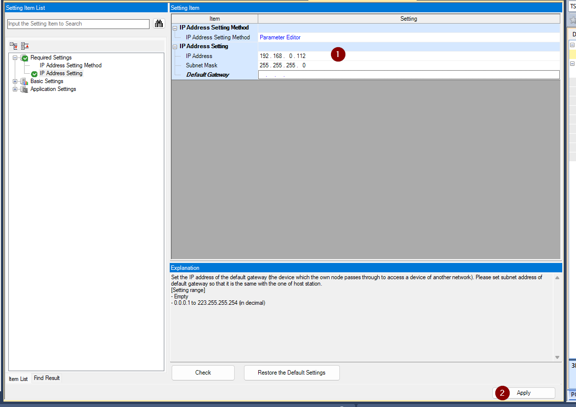
Set the IP address according to the network and apply the setting with Apply.
Simple CPU Communication Setting
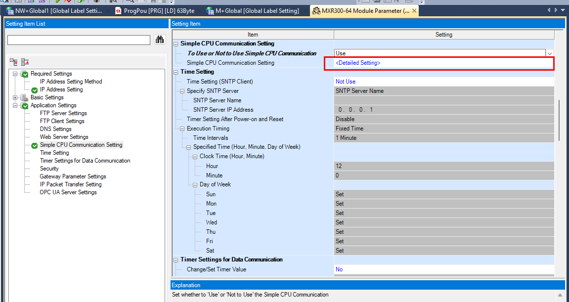
Next, to enable the Simple CPU Communication setting, go to Application Settings Simple PLC Communication Settings and set the part in the red frame to USE.
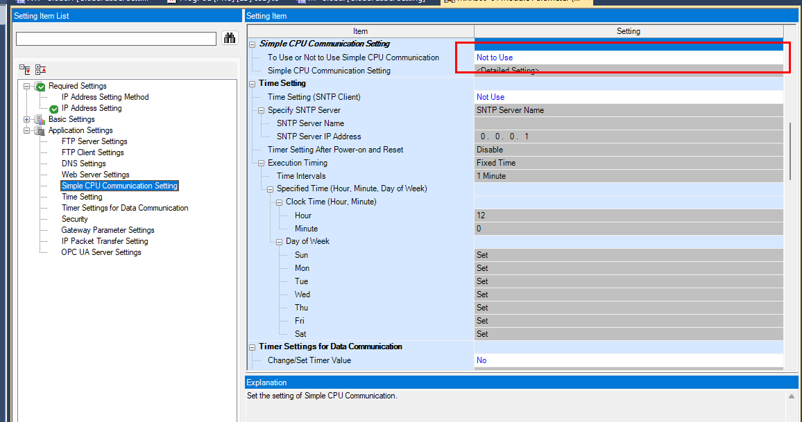
Next, click Detail Setting below.
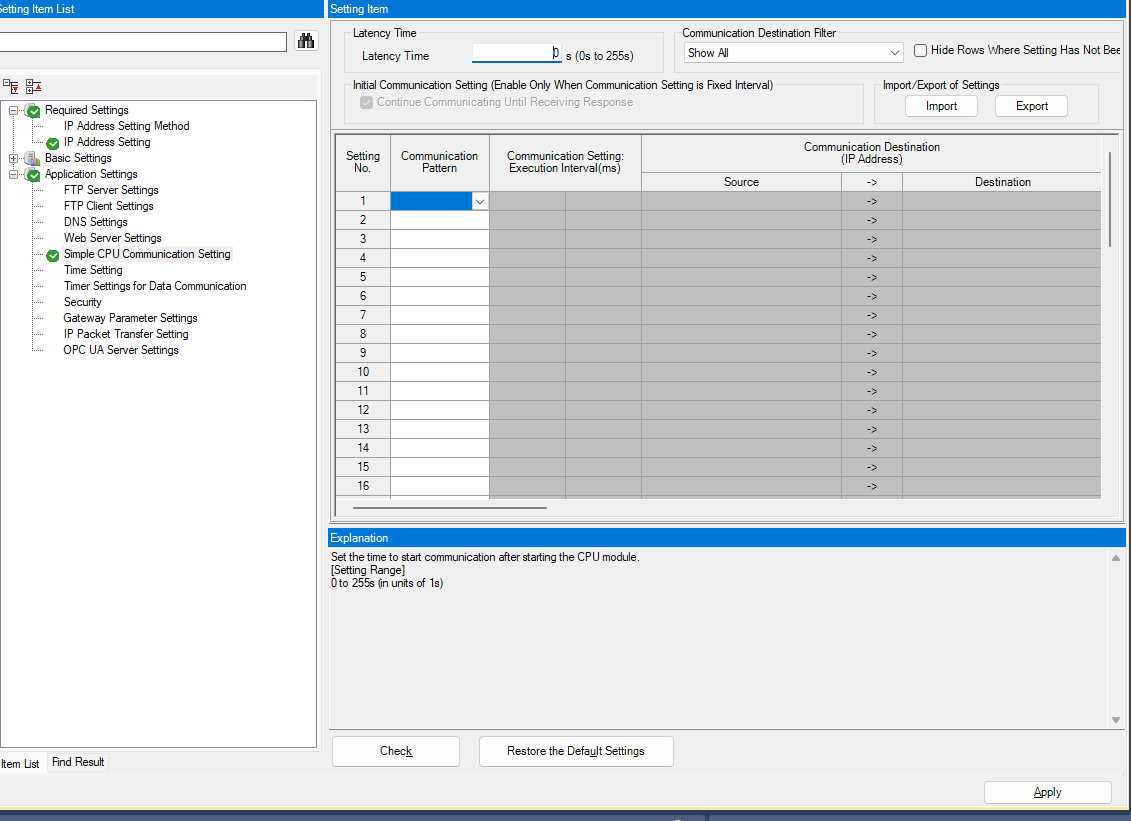
This is the Simple PLC Communication setting screen.
SLMP-Compatible Device
Communication Setting – Communication Pattern
First, set whether the connection corresponding to the Communication Pattern is read or write (from the controller’s perspective).
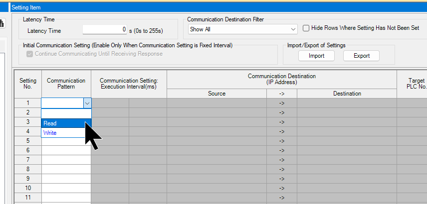
First, set the read command.
Communication Setting – Source
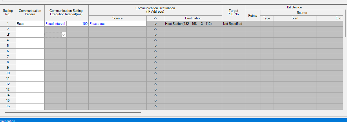
Now, set the Source (connection destination).
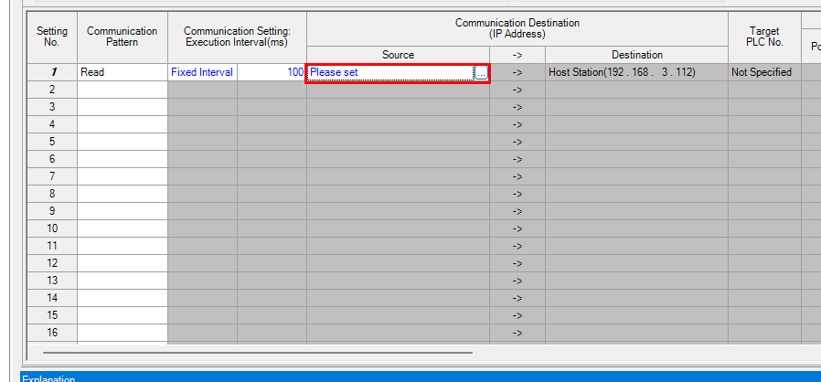
This is the communication source setting screen.
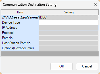
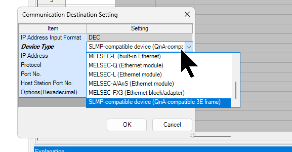
Select the communication method from the Device Type drop-list. This time, we set it to SLMP-Compatible Device.
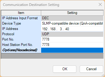
Next, set the IP address and the PORT number to use.
Communication Setting – Target No
Leaving this as No Specified is fine.
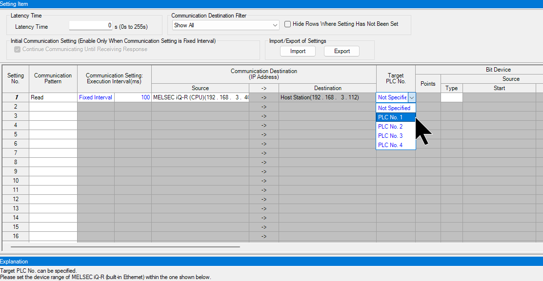
Communication Setting – Source-Bit
Next, set the Bit device type to be acquired from the communication source.
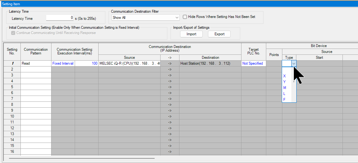
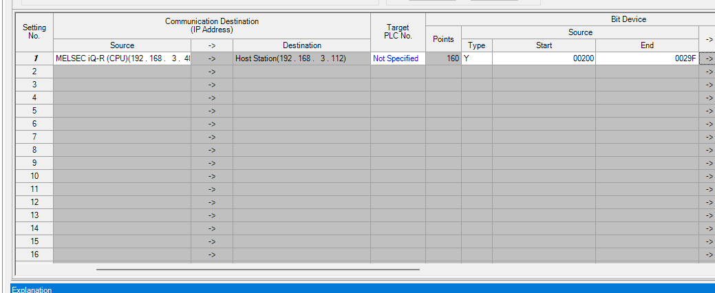
In this example, we specified Y and set it to acquire 160 points of data from Y200 to Y29F.
今回の例ではYに指定し、Y200からY29Fまで160点のデータを取得すると指定しました。
Communication Setting – Source-Word
Now, set the Word device type to be acquired from the communication source.
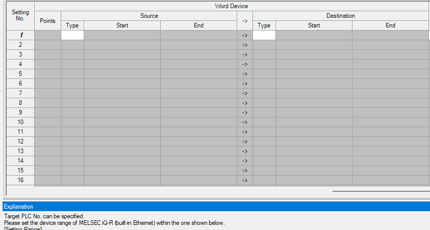
In this example, we specified Y, set it to acquire 100 points of data from D200 to D299, and then transfer the data from D200 to D299.
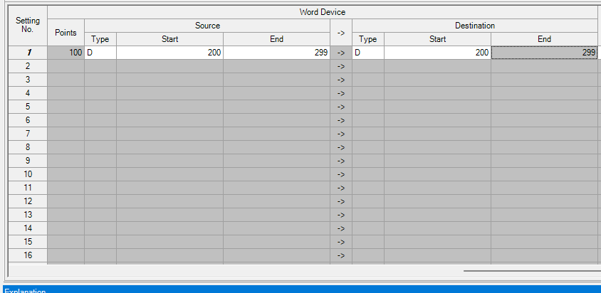
Finally, click the Check button to check for setting errors.
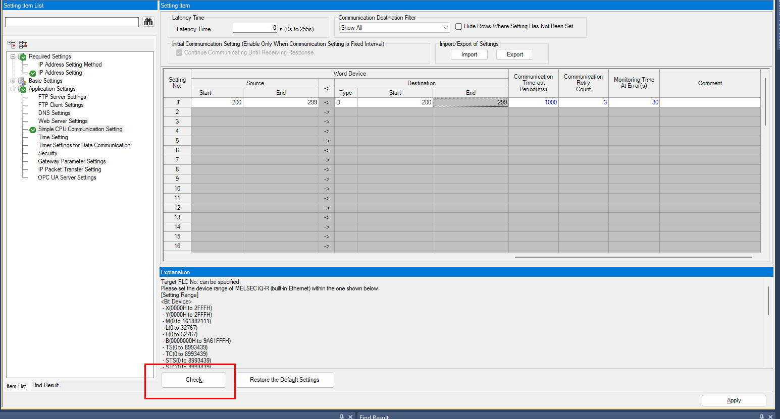
Done!

MELSEC IQ-R(Built-in Ethernet)
Communication Setting – Device Type
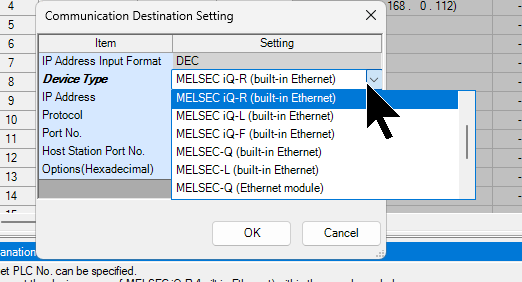
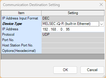
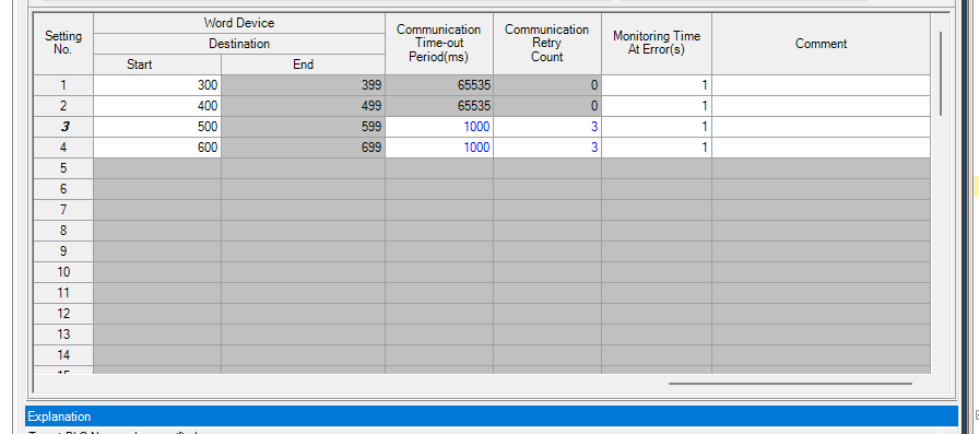
Retry/Monitoring Time
Program
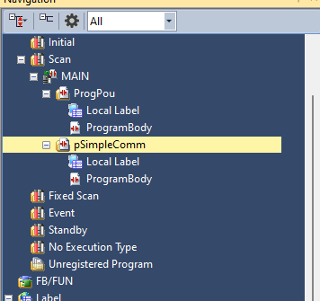
This time, we created a communication test program called pSimpleComm.
Now we will briefly explain the program.
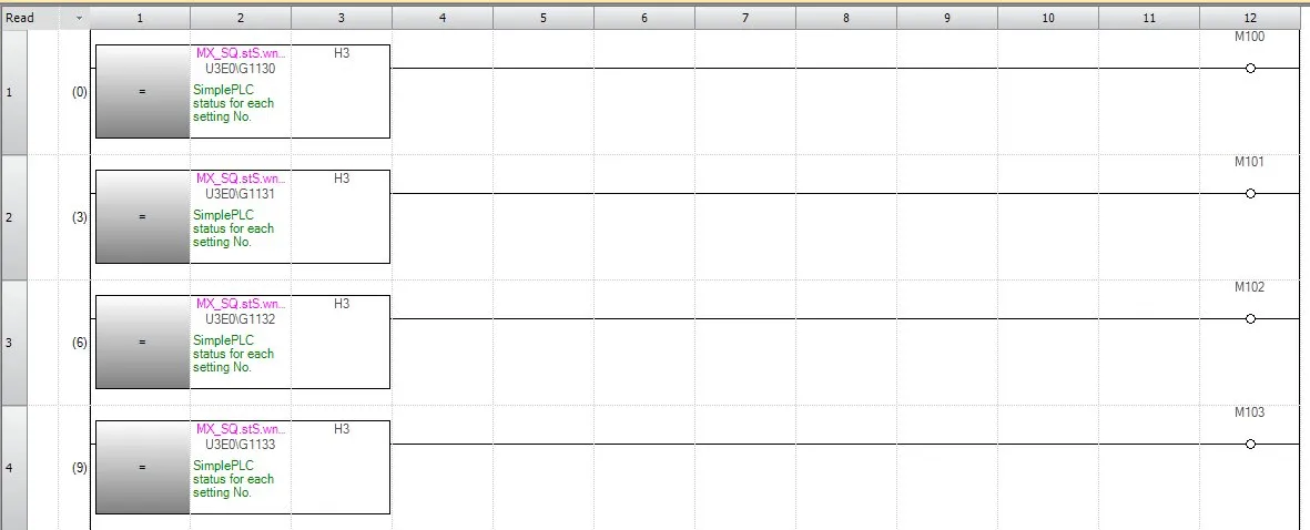
RUNG1-4
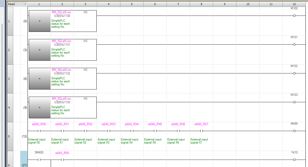
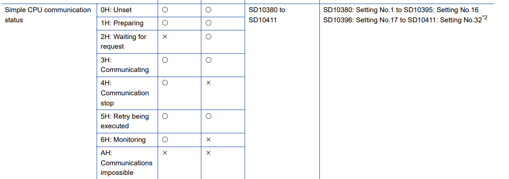
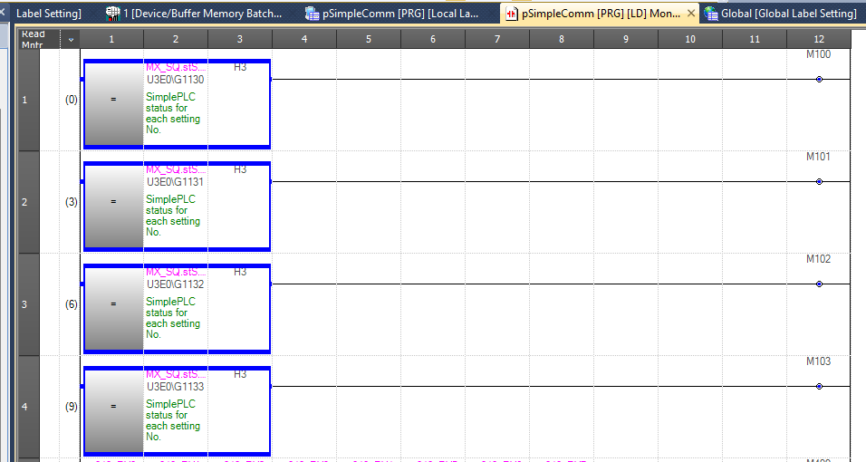
This block is a group of circuits that compare the status word of each setting number of the MX_SQ (SimplePLC) module with the constant H3, and turn ON the corresponding auxiliary relay if they match.
Rung5
This rung is a circuit that turns ON the auxiliary relay M499 when all 8 external input signals X0 to X7 (st040_RX0 to st040_RX7) are ON.

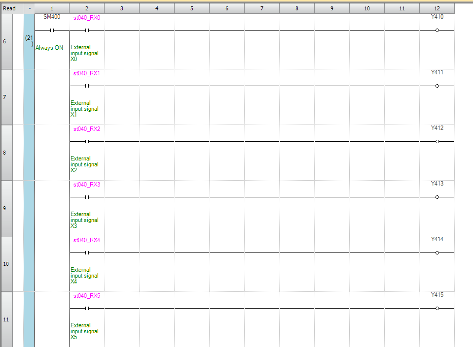
Rung6-11
This is a program that mirrors remote inputs to local outputs and transfers them to the IQ-R.
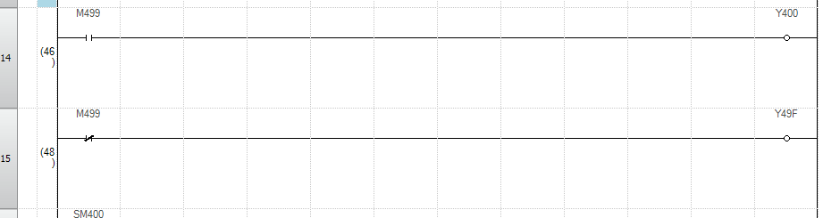
Rung14-15
This is also a program that transfers data from the MXR controller to the IQ-R.
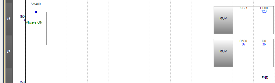
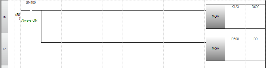
Rung16
This is also a program that transfers data (Word device) from the MXR controller to the IQ-R.
Download
Finally, let’s download the project to the MXR controller.
Results
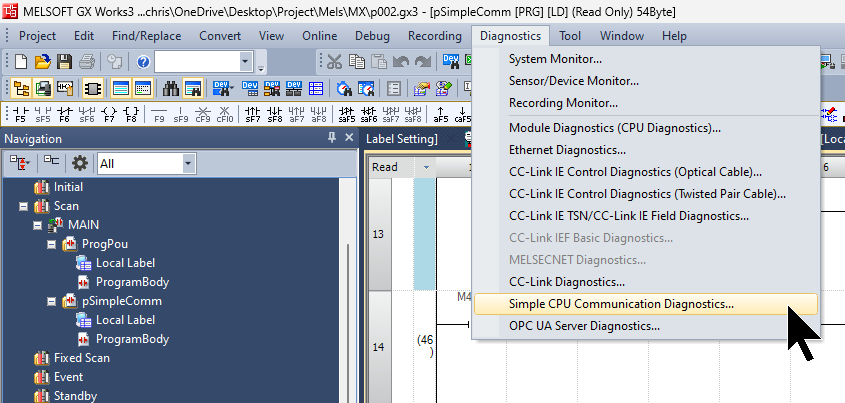
First, check the communication status from GXWORKS3. Click Diagnostics Simple CPU Communication Diagnostics.
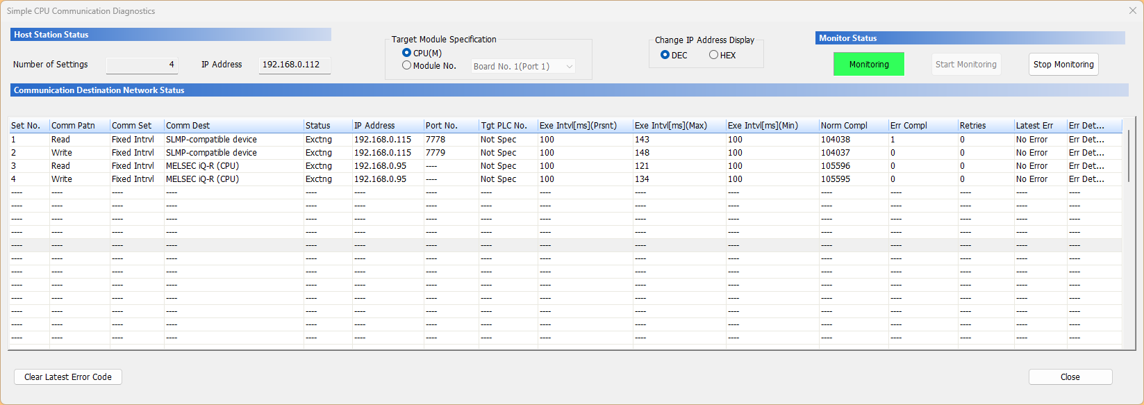
Done! Currently, all 4 connections are communicating normally.
We were also able to confirm that all 4 connections are fine on the program.
Data exchange of bit devices and word devices between the IQ-R and MXR controllers was also successful.