In the Last part we used TwinCAT I/O Devices to communicate with the S7-CPU.Now we can make some PLC Program for display etc.But before we start it, let’s’ talk a little bit about TF6620.
S7 Communication is a Protocol from Siemensa and we can use this Protocol to communicate with Siemens Devices(Input/Output/DB).
S7-300/400/1200/1500 are supported by TF6200 and we can implement it in I/O Devices or PLC Function Blocks.
Here is part1:
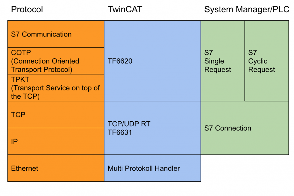
If viewed from the Protocol side, S7 Communication is used to communicate with S7-CPU with COTP,TPKT Protocol.
If viewed from the TwinCAT side, S7 Communication is done by TF6620 and TCP/UDP RT is done by TF6631.
Finally, if viewd from the PLC side, the S7 Single Request and S7 Cyclic Request are implemented ,and we have the S7 Connection Object.

Implemtation
Let’s create some programs!
DUT
Firstly we will create the DUT to group all Connection State,Error,Reset into one variables.
DUT_Comm_S7
In this DUT, we have the Status and Control variables inside the S7 Connector.
| TYPE DUT_Comm_S7 : STRUCT //Input Error AT %I* :BOOL; State AT %I* :BYTE; //Output Reset AT %Q* :BOOL; //Req Input ReceiveCounter AT %I* :BYTE; ErrorID AT %I* :WORD; //Req Output WriteToS7Enable AT %Q* :BOOL; SendRequest AT %Q* :BYTE; END_STRUCT END_TYPE |
DUT_Comm_S7_Object1
And then we will define the DUT for write/read the variables with Siemens.Do you remember these variables that Created in the last tutorial?
Sorry that I am very lazy to create the request separately, I will create a DUT_Comm_S7_Object1 that is extended from DUT_Comm_S7.
It means that if we would like to create another request – we only just Extend the DUT_Comm_S7 again!

It would be like this:
| TYPE DUT_Comm_S7_Object1 EXTENDS DUT_Comm_S7 : STRUCT //Read From S7 rDB1_DBD0 AT %I* :DWORD; rDB10_DBD4 AT %I* :REAL; rDB11_DBX0_7 AT %I* :BOOL; //Write to S7 wDB20_DBD0 AT %Q* :REAL; wDB20_DBW4 AT %Q* :INT; wDB20_DB6_3 AT %Q* :BOOL; END_STRUCT END_TYPE |
FC
Now we can create some Function.In this tutorial there are 2 functions , and display the status from Connector and Display in the PLC HMI.
FC_CheckS7ConnectorIsError
Check the Status of S7 Connection and Return True if the status is 16#F1 or 16#F5.
| FUNCTION FC_CheckS7ConnectorIsError : BOOL VAR_INPUT ID :BYTE; END_VAR FC_CheckS7ConnectorIsError:=FALSE; CASE id OF 16#F1,16#F2,16#F3,16#F4,16#F5: FC_CheckS7ConnectorIsError:=TRUE; END_CASE |
FC_GetS7ConnectorStatusText
A String with the Connector status is returned and displayed in PLC HMI.
| FUNCTION FC_GetS7ConnectorStatusText : STRING VAR_INPUT ID :BYTE; END_VAR CASE ID OF 16#00: FC_GetS7ConnectorStatusText:=’idle’; 16#01: FC_GetS7ConnectorStatusText:=’Start’; 16#10: FC_GetS7ConnectorStatusText:=’TCP setup’; 16#11: FC_GetS7ConnectorStatusText:=’TCP setup wait for response’; 16#20: FC_GetS7ConnectorStatusText:=’COTP setup’; 16#21: FC_GetS7ConnectorStatusText:=’COTP setup wait for response’; 16#30: FC_GetS7ConnectorStatusText:=’S7 setup’; 16#31: FC_GetS7ConnectorStatusText:=’S7 setup wait for response’; 16#40: FC_GetS7ConnectorStatusText:=’is connected’; 16#F1: FC_GetS7ConnectorStatusText:=’TCP error’; 16#F2: FC_GetS7ConnectorStatusText:=’TCP setup error’; 16#F3: FC_GetS7ConnectorStatusText:=’TCP timeout’; 16#F4: FC_GetS7ConnectorStatusText:=’COTP setup error’; 16#F5: FC_GetS7ConnectorStatusText:=’S7 setup error’; 16#FF: FC_GetS7ConnectorStatusText:=’Reset’; END_CASE |
Function Block
This Function Block will link with send/receive the data with S7-CPU and also display the status and value of variables in HMI.
FB_Communication_S7
| FUNCTION_BLOCK FB_Communication_S7 VAR // Connector:DUT_Comm_S7_Object1; //HMI hmiConnectorStatusText :STRING; hmiConnectorStatusError :BOOL; hmiConnectorReset :BOOL; hmiRequestReceiveCounter :BYTE; hmiRequestErrorID :WORD; hmiRequestWriteToS7Enable :BOOL; hmiRequestSendRequest :BOOL; hmiReadFromS7DB1DBD0 :DWORD; hmiReadFromS7DB10DBD4 :REAL; hmiReadFromS7DB11DB0_7 :BOOL; hmiWriteToS7DB20DBD0 :REAL; hmiWriteToS7DB20DBW4 :INT; hmiWriteToS7DB20DBX6_3 :BOOL; ReceiveConuterBackUp :byte; //Internal FB _R_TRIG :ARRAY[0..3]OF R_TRIG; _Ton :ARRAY[0..3]OF ton; END_VAR |
| //Counter hmiRequestReceiveCounter:=Connector.ReceiveCounter; //Rest Connector.Reset:=hmiConnectorReset; //Request Connector.WriteToS7Enable:=hmiRequestWriteToS7Enable; _R_TRIG[0](CLK:=hmiRequestSendRequest); IF _R_TRIG[0].Q THEN Connector.wDB20_DBD0:=hmiWriteToS7DB20DBD0; Connector.wDB20_DBW4:=hmiWriteToS7DB20DBW4; Connector.wDB20_DB6_3:=hmiWriteToS7DB20DBX6_3; Connector.SendRequest:=Connector.SendRequest+1; //Read From S7 CPU hmiReadFromS7DB1DBD0:=Connector.rDB1_DBD0; hmiReadFromS7DB10DBD4:=Connector.rDB10_DBD4; hmiReadFromS7DB11DB0_7:=Connector.rDB11_DBX0_7; END_IF //Counter Checker IF hmiRequestReceiveCounter <> ReceiveConuterBackUp THEN ReceiveConuterBackUp:=hmiRequestReceiveCounter; END_IF; //hmi Dislpay hmiConnectorStatusText:=FC_GetS7ConnectorStatusText(Connector.State); hmiConnectorStatusError:=FC_CheckS7ConnectorIsError(Connector.State); hmiRequestReceiveCounter:=Connector.ReceiveCounter; hmiRequestErrorID:=Connector.ErrorID; |
POU
Finally we will call it the Main POU.
| PROGRAM MAIN VAR S7:FB_Communication_S7; b:bool; END_VAR S7(); |
TwinCAT I/O Devices
Compile your project to check for any error.
Now we can Link the variables to I/O Devices.
Right Click the State>Change Link.
Choose MAIN.S7.Connector.State as the variable.
And then do the same operation for other variables also.
PLC HMI
This is the screen for display the S7-CPU variables and the status.
Test
Let’s write some values on the Siemens Side.
If you see “is connected” displayed on the TwinCAT side, the connection is ok!
The Send Request is sent while the hmiRequestWriteToS7Enable and hmiRequestSendRequest button is pressed.
we will see the value from Siemens CPU.
And Also we will see the value from TwinCAT3.
Please download the project from this link:
https://github.com/soup01Threes/TwinCAT3/blob/main/TwinCAT_Project_TF6620__2.zip