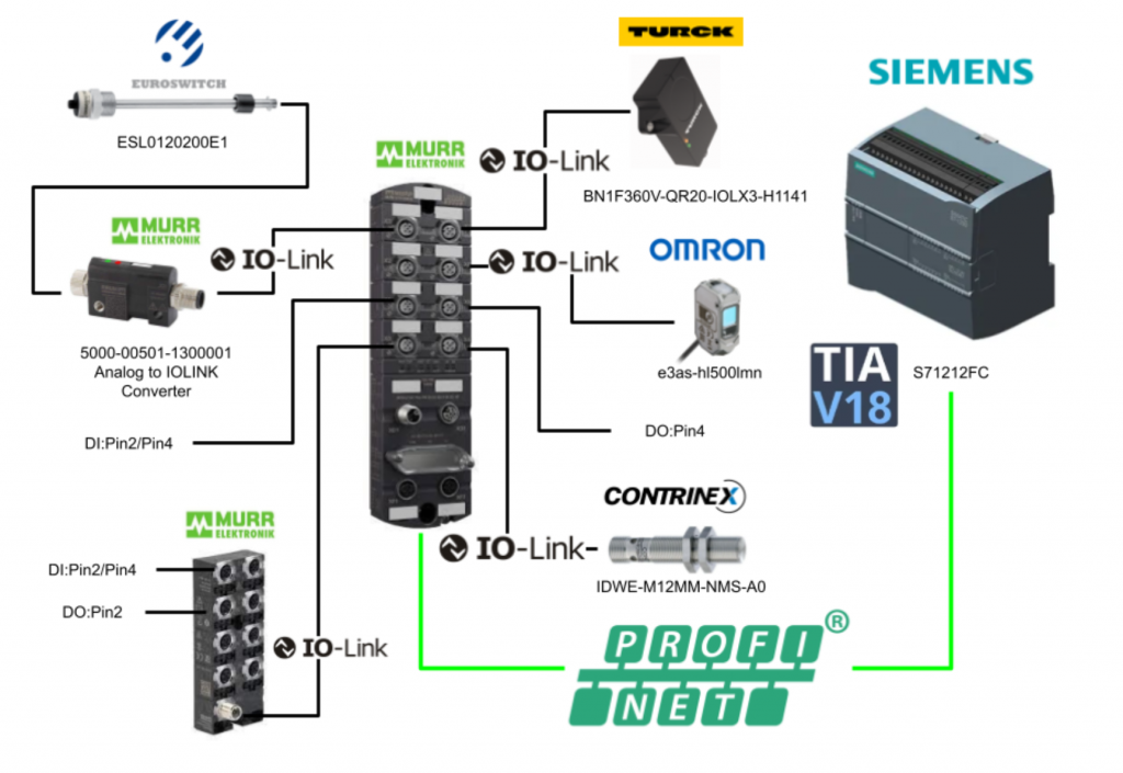
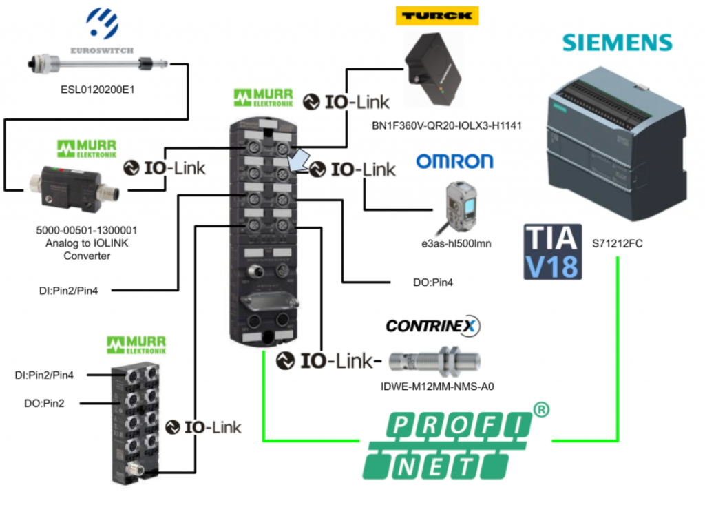
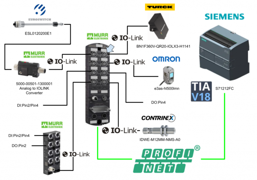
This article uses Murrelektronik’s IMPACT67 Pro PN DIO8 IOL8 M12L 5P for Profinet communication with Siemens S7-1212FC.
For the IOLINK devices, this time using Murrelektronik’s IO-Link HUB and analogue>IO-Link converter, TURCK’s BN1F360V-QR20-IOLX3-H1141, OMRON’s e3as-hl500lmn and IDWE-M12MM-NMS-A0 from CONTRINEX.
Let’s get started!
IMPACT67 Pro PN DIO8 IOL8 M12L 5P?
The Murrelektronik IO-LINK Master IMPACT67 Pro PN DIO8 IOL8 M12L 5P used in this project is,PROFINET Device compatible, M12 L Code 5 Pin power supply and 8 Port M12 Port (DI/DO/IOLINK configurable).
This is the Profinet Fieldbus specification.
59719?
This is an IOLINK-Hub made by MURRELEKTRONIK.
- 50 mm plastic housing
- 1 x M12 IO-Link class A
- 8 x M12 I/O
- 16 configurable inputs and outputs
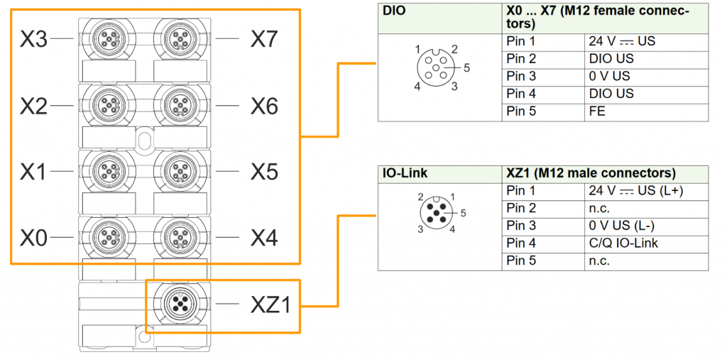
This is the Layout of the 59719 MURRELEKTRONIK IOLINK-Hub used in this article.
XZ1 is the device power supply and IOLINK Port (Class A), while X0 to X7 are input or output Ports.
Process Data
This is the input Process Data for the 59719 IO-Link Hub.
Byte 2 and Byte 3 are only for E0 types and do not apply to the 59719 used in this article.
This is the output Process Data of the 59719 IO-Link Hub.
EUROSWITCH?
This device from EUROSWITCH – with 4-20 mA analogue level sensor + 2 programmable digital thresholds, also available for water – mineral oil – diesel fuel – petrol.
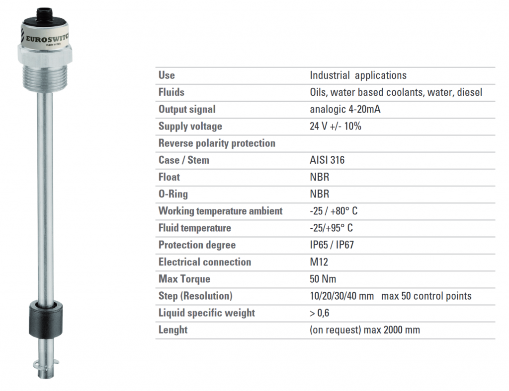
Find out more information from this Link.
Pin Assignment
This is the Pin arrangement of the level sensor.
IO-Link converter with analog input
This is a Converter that converts analogue input to IOLINK data from MURRELEKTRONIK.
- Analogue input side is M12 female A-Code Connector
- IOLINK side is M12 male A-Code Connector
- Resolution 16 bits
- Deviation 45 ppm
- Sampling rate ≤200 Hz
In fact, MURRELEKTRONIK also offers various Converters, which can be used for a variety of applications. Incidentally, the one used in this case is 5000-00501-1300001.
5000-00501-1300001 can convert the following four analogue input types.
Pin Assignment-Analog Side
This is a pin layout diagram for the analogue input side.
Pin Assignment-IO LINK Side
This is the Pin layout diagram on the IOLINK side.
LED
MURRELEKRNIK analogue input>IOLINK converters have LED1 and LED2 to indicate the status of the device, see MANUAL for more information on LEDs.
Range
This is the Range when set to analogue input 4…20 mA.
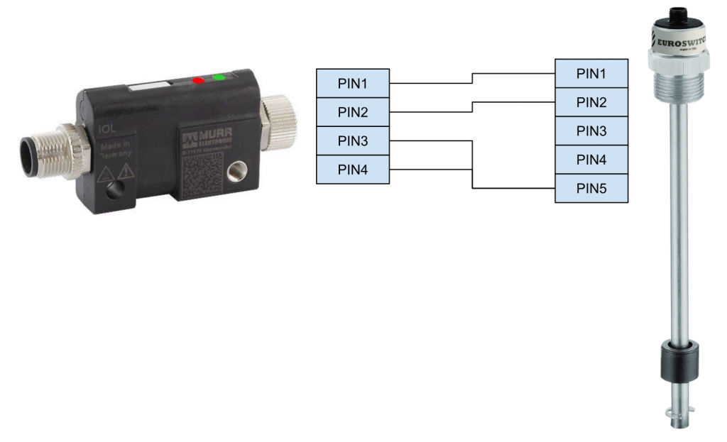
Wiring
This is the wiring for a MURRELEKTRONIK analogue input > IO-Link converter and EUROSWITCH level sensor.
TURCK BN1F360V-QR20-IOLX3-H1141?
This is a TURCK angle detection IOLINK sensor.
- LED status display
- Angle detection with single axis (measuring range 360 °)
- Temperature detection: -40 °C to 85 °C (acyclic communication, accuracy ±3 °C)
- Protection class IP68/IP69K
- DC 18 to 30 V
- M12 x 1 male connector, 4-pin
- IO-Link communication support
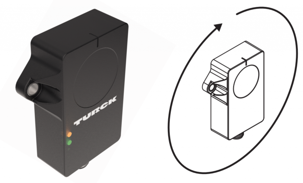
These are the specifications for the BN1F360V-QR20-IOLX3-H1141 used in this project.
Process Data
This is Process Data for TURCK BN1F360V-QR20-IOLX3-H1141.
Pin Assignment
This is a Pin layout diagram for TURCK BN1F360V-QR20-IOLX3-H1141.
Implementation
Siemens Side
Hardware Configuration
Add new device
Add new device to add S7-1212FC to the project.
The Add new device screen is displayed.
CPU1212FC DC/DC/DCを選び>OKで進みます。
The new TIA has enhanced security settings and allows you to add a Password setting depending on the application. On this screen, you can set whether a Password is added to the TIA project.
Here you can set whether the PLC can be accessed outside of Siemens engineering tools and HMIs.
The next step is to set the access level.
Recheck all settings and complete with Finish.
Download and Install GSDML
To set up a Profinet network, you need to obtain a GSDML File. Download the GSDML File from the Link below.
Click Options>Manage general station description files (GSD).
The GSDML management screen appears and the … button is clicked.
Select the GSDML Folder that was downloaded earlier.
Done!GSDML File found Install installs the GSDML File.
Done!
Add MURRELEKRNIK IO LINK Device
Next, click on Device & Networks to add Murrelektronik IO-Link devices.
Drop Other field devices>Murrelektronik>IMPACT67 Pro>V1.0>54630…
MURRELEKRNIK’s IO-Link Master has been added.
Configure Profinet Network
Next, click on Not Assigned and select PLC_1.PROFINET interface_1 to connect the S71200 with PROFINET.
Done!
IP Address
Click Show address labels.
The IP address of each device is displayed and should be set according to the application.
Device Name
The device name is important in PROFINET networks, click on MURRELEKRNIK IO-Link Master.
Set the device name in Properties>PROFINET>Ethernet address>PROFINET.
Assign Device Name
If you are already connected to the actual device, you can now directly assign the device name of the MURRELEKTRONIK IO-Link Master. Right-click on the device>Assign device name.
The Assign PROFINET device name screen is displayed.
You can search for PROFINET devices currently in the network using the Update list and assign device names using the “Assign name”.
Configure Port
Next, double-click on the device to build each port of the MURRELEKTRONIK device.
This is the Port construction screen.
Port X0
PortX0 is connected to MURRELEKTRONIK ‘s configurable 16 input/output IOLINK HUB 59719.
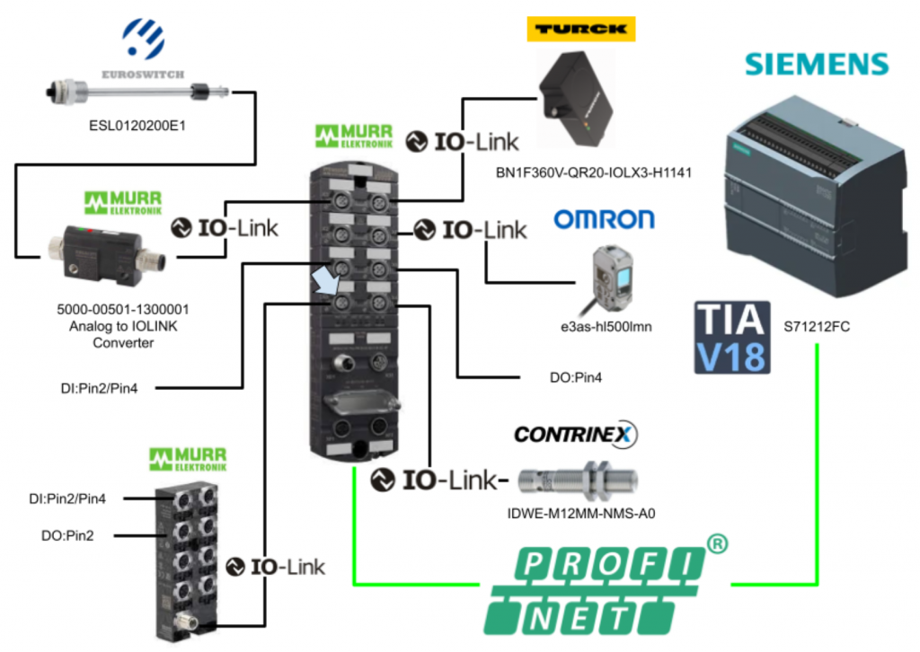
Add Submodule>Murrelektronik IO-Link devices>Digital hubs+PQI>59719 from the Catalog to Slot1 X0 and set I address and Q address.
Port X1
Digital inputs and connections are also made to Pin 2 and Pin 4 of PortX1.
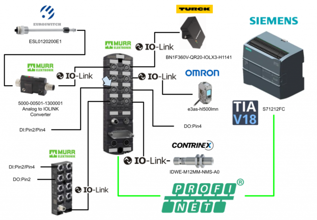
Add Submodule>Generic IO-Link Devices>SIO Module>Standard digital Input from Catalog to Slot1 X1 and set I address.
Port X2
PortX2 is an empty Port.
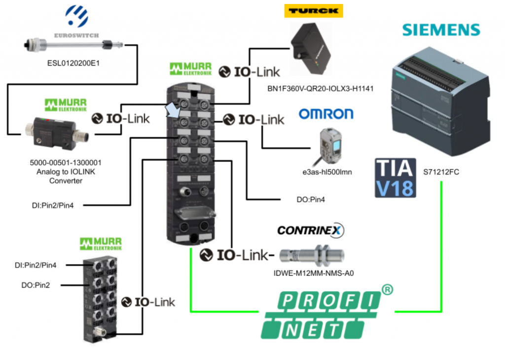
Add Submodule>Generic IO-Link Deviecs>Deactivated from Catalog to Slot1 X2.
Port X3
PortX3 is connected to a configurable analogue input>IOLINK converter from MURRELEKTRONIK, the analogue input being an ESL0120200E1 4-20 mA level sensor from EUROSWITC.
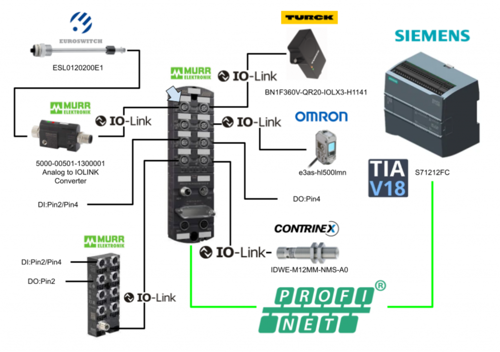
In Slot 1 X3, from the Catalogue, add Submodule>Murrelektronik IO-Link devices>Analog Input Converter+PQI>500x-00501-1300001 … and set the I address.
Set Process data lower limit/upper limit and Device Function.
This time, set the 4…20 mA conversion function.
Port X4
PortX4 connects to CONTRINEX IOLINK sensor IDWE-M12MM-NMS-A0.
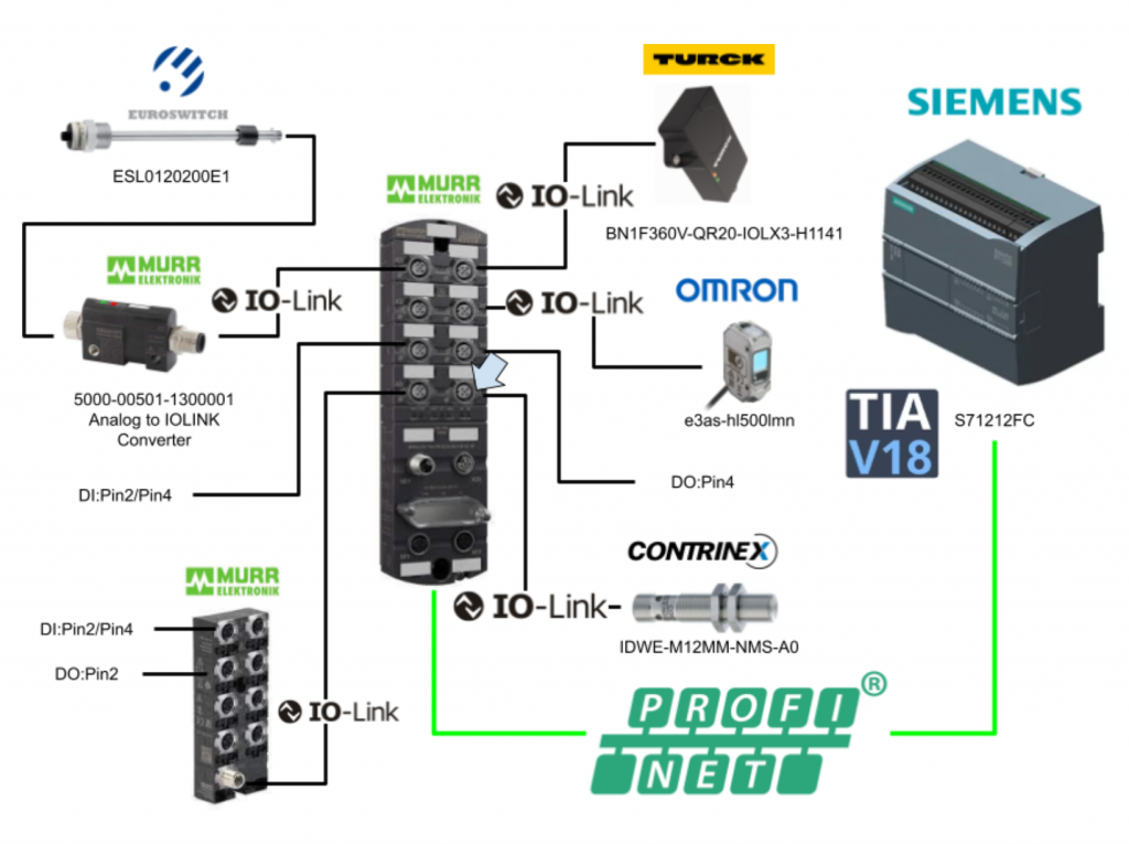
Add Submodule>Generic IO-Link Devices>Generic Input and output devices+PQI>IO-Link In/Out 04/02 Bytes+PQI from the Catalog to Slot 1 X4 and set I address and Q address.
Generic Input and output devices+PQI>IO-Link In/Out 04/02 Bytes+PQI is set because the IDWE-M12MM-NMS-A0 from CONTRINEX has 4 Bytes input and 1 Bytes output IO-Link data.
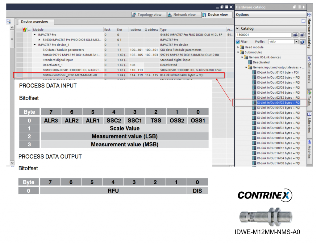
Port X5
PortX5 is connected to the digital output.
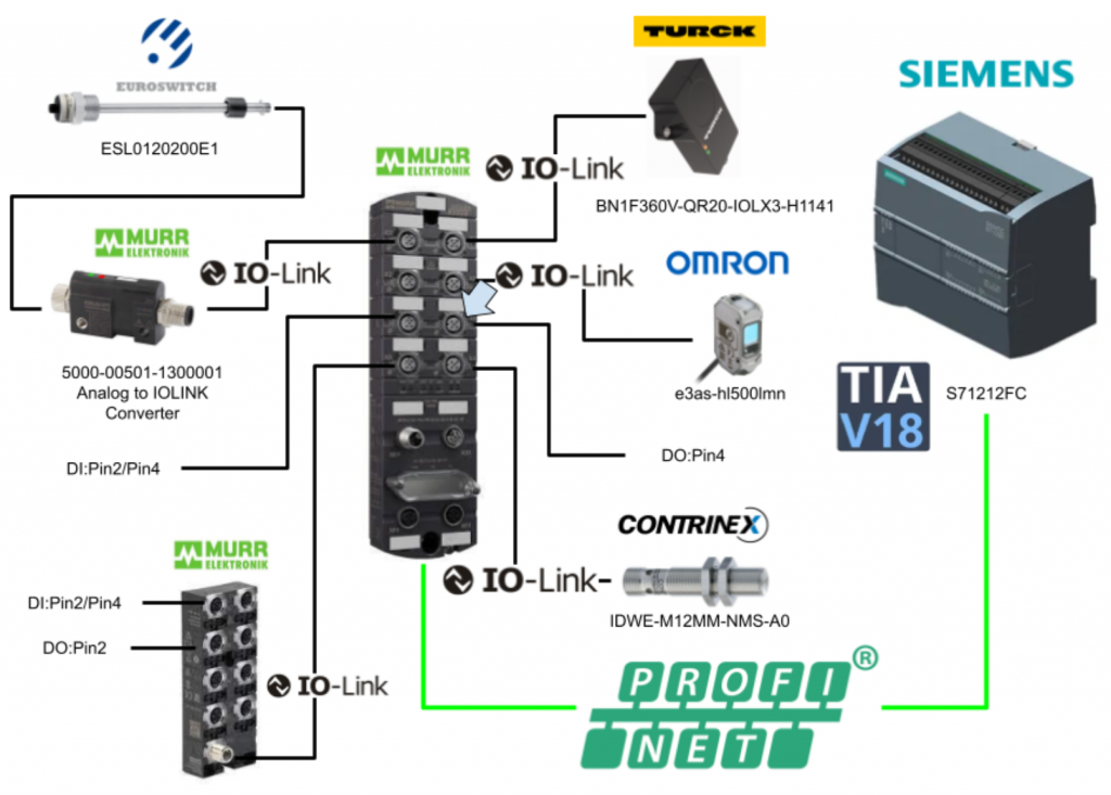
Add Submodule>Generic IO-Link Devices>SIO Module>Standard digital Output from the Catalog to Slot1 X5 and set the Q address.
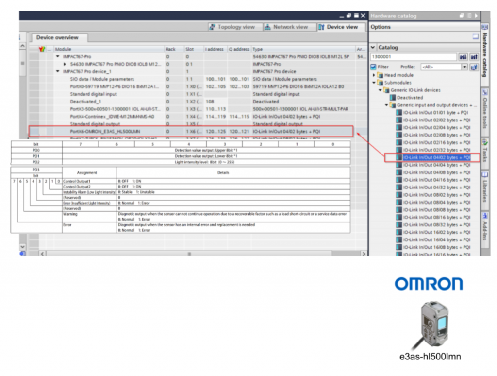
Port X6
PortX6 is connected to the OMRON IOLINK sensor E3AS-HL500L-MN.
Add Submodule>Generic IO-Link Deviecs>Generic Input and output devices+PQI>IO-Link In/Out 04/02 Bytes+PQI from the Catalogue to Slot 1 X6 and set I address and Q address.
Generic Input and output devices+PQI>IO-Link In/Out 04/02 Bytes+PQI is set because the OMRON E3AS-HL500L-MN has 4 Bytes input and 1 Bytes output IO-Link data.
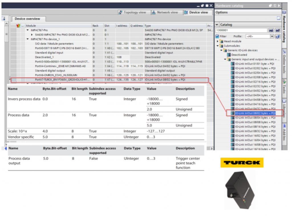
Port X7
PortX7 connects to TURCK IOLINK sensor BN1F360V-QR20-IOLX3-H1141.
Add Submodule>Generic IO-Link Devices>Generic Input and output devices+PQI>IO-Link In/Out 08/02 Bytes+PQI from the Catalog to Slot1 X7 and set I address and Q address.
Generic Input and output devices+PQI>IO-Link In/Out 04/02 Bytes+PQI is set because TURCK’s BNF-360V-QR2-IOLX3-H1141 has 8 Bytes of input and 1 Bytes of output IO-Link data.
Option Slot
Add web server functionality to the Option Slot.
Clock Tags
Add a System Memory Bit or Clock Memory Bit under PLC>System and clock memory.
Tags
Define IQ Tags according to address.
Program
Data Unit Type
DUT_Contrinex _IDWE_M12MM-NMS_A0_IN_Byte0
This is the Contrinex IDWE_M12MM-NMS_A0 sensor Byte0 structure.
DUT_Contrinex _IDWE_M12MM-NMS_A0
This is the Contrinex IDWE_M12MM-NMS_A0 sensor structure, which contains the Scale Value and Measure Value as well as the Byte 0 Bool Status.
DUT_EUROSwitch_LevelSeneor
This is the structure of the EUROSwitch level sensor.
This structure summarizes the 4-20 mA analogue input values and level values from the analogue input to IOLINK converted data at MURRELEKTRONIK.
DUT_Murr_IOLinkMaster_PQI
This is the last 1Bytes PQI structure when Port is used as IOLINK Port in MURRELEKTRONIK’s Profinet IO LINK Master. (There are 2Bytes, but the second byte is only the inverted data of the first byte, so it is not defined here.)
DUT_Murr_IOLINKHUB_59719_IN_Bytes2_3
Here is the data for the IO-Link HUB Byte2/Byte3 from MURRELEKTRONIK, Byte2/3 is only for type E0 and does not apply to the 59719 used in this case.
DUT_Murr_IOLINKHUB_59719_IN
This is a structure that summarises the MURRELEKTRONIK IO-Link HUB data.
DUT_Murr_Submodule 1_SIO_PortBase_Pin
This is the structure used by MURRELEKTRONIK’s Profinet IOLINK Master when the PORT is set as SIO (Standard Input/Output).
DUT_OMRON_E3AS_HL500LMN_IN_Status
This is the structure that summarises the Status of the OMRON IOLINK device E3AS_HL500LMN 3rd Byte.
DUT_OMRON_E3AS_HL5000LMN_IN
This is the structure of Omron’s E3AS_HL500LMN sensor, which includes the DetectValue Output and LightIntensityLevel as well as the Byte3 Bool Status.
DUT_RawArray_Length2
This is a 2Bytes array structure that collectively defines Process Input data (%I).
DUT_RawArray_Length4
This is a 4Bytes array structure that collectively defines Process Input data (%I).
DUT_RawArray_Length8
This is an array structure of 8Bytes that defines a collection of Process Input data (%I).
DUT_TURCK_BN1F360V_QR20_IOLX3-H1141_IN
This is a structure that summarises the input data for TURCK’s BN1F360V-QR20-IOL3-H1141.
DUT_TURCK_BN1F360V_QR20_IOLX3-H1141_OUT
This is a structure that summarises the output data of TURCK’s BN1F360V-QR20-IOL3-H1141.
Function Block
FB_Contrinex _IDWE_M12MM-NMS_A0
This is a Function Block that converts the raw data of the Contrinex IOLink device IDWE-M12MM-NMS-A0.
Interface
This is the Interface of the Function Block.
Network1
Bit 0 of Byte 3 is the OSS1 output of Contrinex’s IDWE-M12MM-NMS-A0.
Network2
Bit 1 of Byte 3 is the OSS2 output of Contrinex’s IDWE-M12MM-NMS-A0.
Network3
Bit 2 of Byte 3 is the TSS1 output of Contrinex’s IDWE-M12MM-NMS-A0.
Network4
Bit 3 of Byte 3 is the SSC1 output of Contrinex’s IDWE-M12MM-NMS-A0.
Network5
Bit 4 of Byte 3 is the SSC2 output of Contrinex’s IDWE-M12MM-NMS-A0.
Network6
Bit 5 of Byte 3 is the ALR2 output of Contrinex’s IDWE-M12MM-NMS-A0.
Network7
Bit 6 of Byte 3 is the ALR3 output of Contrinex’s IDWE-M12MM-NMS-A0.
Network8
Bit 7 of Byte 3 is the ALR1 output of Contrinex’s IDWE-M12MM-NMS-A0.
Network9
Byte 2 is the ScaleValue of Contrinex’s IDWE-M12MM-NMS-A0.
Network10
Byte 0 and Byte 1 are the Measure Value of Contrinex’s IDWE-M12MM-NMS-A0.
FB_EUROSwitch_LevelSeneor
This level sensor from EUROSWITCH is a Function Block that converts the raw data of IO devices acquired from the analogue input>IOLINK converter connected to MURRELEKTRONIK .
Interface
This is the Interface of the Function Block.
Network1
Network1 SWAPs values converted to 4-20 mA obtained from MURRELEKTRONIK .
Network2
Network2 converts the values converted earlier to 4-20 mA and 0-100% level values.
Network3
Network3 outputs the result of the previous operation to the Function Block.
FB_Murr_IOLINKDevices_PQI
This is the (last 2 Bytes) Port diagnostic information that comes with MURRELEKTRONIK ‘s IOLink Master.
Interface
This is the Interface of the Function Block.
Network1
Network1 uses the SCATTER function to batch transfer Byte data into structures.
Network2
Network2 outputs Bit0 values to NewPar.
Network3
Network3 outputs Bit3 values to SubstDev.
Network4
Network4 outputs Bit4 values to PortActive.
Network5
Network5 outputs Bit5 values to DevCom.
Network6
Network6 outputs Bit6 values to DevErr.
Network7
Network7 outputs Bit7 values to PQ.
FB_Murr_IOLINKHUB_59719
This one extracts IOLink Hub data and PQI information from MURRELEKTRONIK (59719 is not applicable as it is not an E0 type, but we made it just in case).
Interface
This is the Interface of the Function Block.
Network1
Network1 transfers the 0-byte and 1-byte data together in the internal variable Word.
Network2
Network2 uses the SCATTER function to batch transfer Word data into a structure.
Network3
Network3 forwards the Bit0 value of Byte3 to ErrorAtPowerSupply.
Network4
Network4 transfers the Bit1 value of Byte3 to ErrorAtTempature.
Network5
Network5 forwards the Bit2 value of Byte3 to ErrorAtInOuty.
Network6
Network6 transfers the Bit3, Bit4, Bit5 and Bit6 values of Byte3 together to the DIA.
Network7
Network7 transfers the Bit7 value of Byte 3 to GlobalStatus.
Network8
Network8 forwards the Byte4 value to DeviceIdentification.
Network9
Network9 uses the GATHER function to transfer the structure data together into Word.
Network10
Network11 retransfers the Byte0 and Byte1 values of the Word to the output data.
FB_TURCK_BN1F360V_QR20_IOLX3_H1141
This is a Function Block that converts the raw data of TURCK’s IOLink device BN1F360V-QR20-IOLX3-H1141.
Interface
This is the Interface of the Function Block.
Network1
Network1 transfers Byte0 and Byte1 SWAPs to the inverted Process Data.
Network2
Network2 SWAPs Byte 2 and Byte 3 and forwards them to Process Data.
Network3
Network3 transfers Byte 4 to the Scale variable.
Network4
Network4 transfers Byte 5 to the VendorSpecific variable.
FB_OMRON_E3AS_HL5000LMN
This is OMRON’s E3AS-3AS-HL500-MN Function Block for converting raw data from IO devices.
Interface
This is the Interface of the Function Block.
Network1
SWAP Byte0 and Byte1 and output them as DetectValueOutput values.
Network2
Btye2 is the IntensityLevel value.
Network3
Bit 0 of Byte 3 is ControlOutput 1 of OMRON’s E3AS-3AS-HL500-MN.
Network4
Bit 1 of Byte 3 is ControlOutput 2 of OMRON’s E3AS-3AS-HL500-MN.
Network5
Bit 2 of Byte 3 is the InstabilityAlarm of OMRON’s E3AS-3AS-HL500-MN.
Network6
Bit 4 of Byte 3 is an InsufficinetError for OMRON’s E3AS-3AS-HL500-MN.
Network7
Bit 6 of Byte 3 is a Warning for OMRON’s E3AS-3AS-HL500-MN.
Network8
Bit 7 of Byte 3 is in Error for OMRON’s E3AS-3AS-HL500-MN.
FB_Murr
Interface
This is the Function Block of FB_Murr, which is connected to MURRELEKTRONIK ‘s IOLINK Master to get the devices of the 8 Ports and the PQI of each Port.
Network1
Network1 reads the input (X1Pin4) of the Port configured as the SIO (standard IO) of MURRELEKTRONIK and sets the output (X5Pin4) to True when that input is set to True.
Network2
Network2 reads the inputs (X2Pin4 and X2Pin2) connected to MURRELEKTRONIK ‘s 16-configurable IOLink Hub 59719 and if X2Pin4 is True, the output is switched on and off at 1 Hz (X3Pin2 repeatedly. X2Pin2 If True, the output is turned on all the way (X3Pin2).
Network3
Network3 uses a MURRELEKTRONIK Analog>IOLINK converter to convert EUROSWITCH 4-20 mA analogue inputs into IOLINK data, which is then transferred to the DB.
Network4
Network4 converts Contrinex IDWE-M12MM-NMS-A0 IOLINK data and transfers it to the DB.
Network5
Network5 converts the IOLINK of the OMRON E3AS-HL500L-MN into data and transfers it to the DB.
Network6
Network6 converts TURCK’s BN1F360V-QR20-IOLX3-H1141 IOLINK data and transfers it to the DB.
DB
DB_MurrIOLINK_Data
This DB brings together the data of each Port as a Struct.
OB1
Finally, you can call FB_Murr with OB1.
Result
From IOLINK Tools
Check the IO-Link Master from MURRELEKTRONIK ‘s IO-Link Tools.” Click on ‘Search Master’.
Done!
Right-click IO-Link Master and click the Assign button.
IO-Link Master has been added to the project.
The next step is to import the IODD File into the tool.
Set the Folder where the IODD File is stored in the Field of Path.
Select the required IODD File >Import.
Now connect with the IO-Link Master via Go Online.
Proceed with Yes.
Next, click on the Check Device button to compare with the Online project.
Click Takeover devices into engineering to download the data to the Offline project.
Done!
In some cases, it may also be necessary to upload the parameters of the IO-Link device.
Click on “Upload from device”.
Done!
In this article we will look at the parameters of Contrinex Sensors in a little more depth.
ALR1/ALR2/ALR3 for the IOLINK output Bit ALR1/ALR2/ALR3.
SSC1 and SSC2 correspond to the outputs of SSC1 and SSC2.
If SSC1 is higher than 10, SSC1 outputs True.
If SSC2 is higher than 5, SSC2 outputs True.
The Process Data Tab allows you to view the inputs and outputs of each IO-Link device.
From TIA
The next step is to check the status of the IO-Link Master from the Siemens TIA tool.
Currently the MURRELEKTRONIK IO-Link Master has a green CHECK MARK and the S7-1200 is communicating with the MURRELEKTRONIK IO-Link Master.
Each Slot has no problems.
This video shows Contrinex working with the IDWE-M12MM-NMS-A0.
Siemens.Connect with murrelektronik PN And Contrinex IOLINK Devices IDWE‐M12MM‐NMS‐A0
This video shows a video that works with MURRELEKTRONIK ‘s analogue>IOLINK converter.
Siemens.Connect with murrelektronik PN And murrelektronik IOLINK Analog Converter
This video shows the IOLink HUB 59719 input from MURRELEKTRONIK in conjunction with the IOLink HUB 59719 input.
Siemens.Connect with murrelektronik PN And murrelektronik IOLINK HUB 59719 INPUT
This video shows the IOLink HUB 59719 output from MURRELEKTRONIK in conjunction with the IOLink HUB 59719 output.
Siemens.Connect with murrelektronik PN And murrelektronik IOLINK HUB 59719 OUTPUT
This video shows a video working with MURRELEKTRONIK ‘s IOLink Master SIO.
Siemens.Connect with murrelektronik PN And murrelektronik IOLINK SIO
This video shows TURCK’s BN1F360V-QR20-IOLX3 H1141 in conjunction with TURCK.
Siemens.Connect with murrelektronik PN And TURCK IOLINK Device BN1F360V‐QR20‐IOLX3 H1141
This video shows a video working with OMRON’s E3AS-HL500LMN.
Siemens.Connect with murrelektronik PN And OMRON IOLINK Device E3AS‐HL500LMN
Download
You can download this project from this Link.
https://github.com/soup01Threes/Siemens/blob/main/TestingMurr.zap18