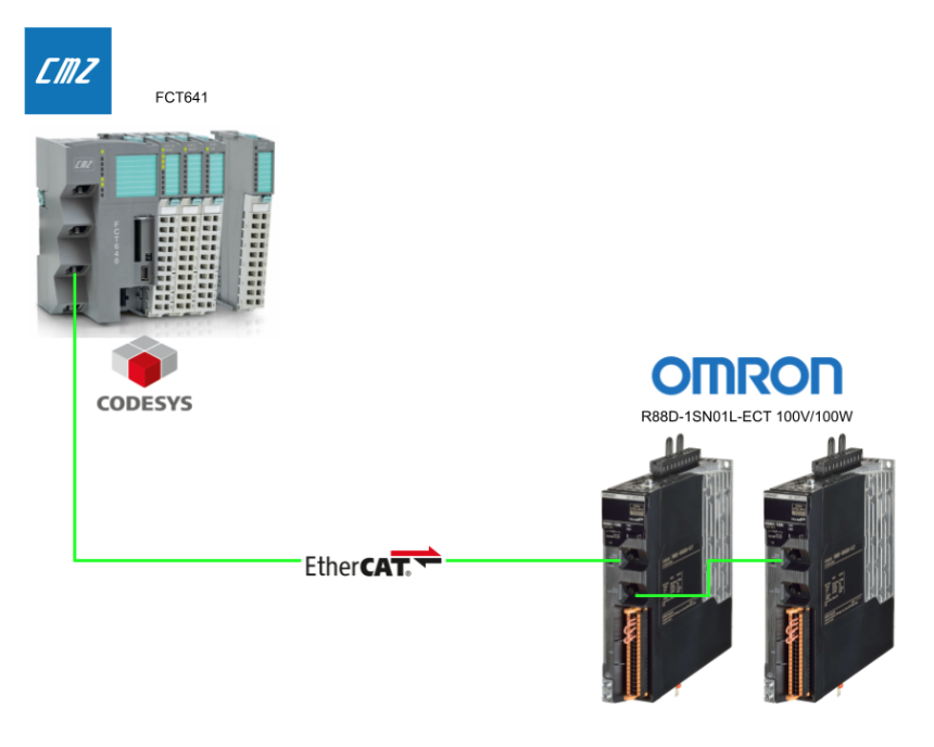
In this follow-up to the previous article, we continue exploring dual-axis control using the CMZ motion controller “FCT641” with CODESYS SoftMotion and OMRON servo drives (R88D-1SN01L-ECT) over EtherCAT.
This time, we focus on MC_GearIn / MC_GearOut to demonstrate master-slave axis synchronization (gear control).
We’ll walk through key topics such as velocity ratio tracking, coupling/decoupling timing, and hands-on HMI-based operation for intuitive testing and tuning.
Come on, let’s enjoy FA!
Foreword
Thank you from the bottom of my heart for visiting my technical blog and YouTube channel.
We are currently running the “Takahashi Chris” radio show with Full-san (full@桜 八重 (@fulhause) / X) which I deliver every Wednesday night.
Sharing, not hoarding, technical knowledge
We publish technical information related to factory production technology and control systems for free, through blogs and videos.
With the belief that “knowledge should be accessible to everyone,” we share practical know-how and real-world troubleshooting cases from our own field experience.
The reason we keep it all free is simple: to help reduce the number of people who struggle because they simply didn’t know.
If you’ve ever thought:
- “Will this PLC and device combination actually work?”
- “I’m having trouble with EtherCAT communication—can someone test it?”
- “I want to try this remote I/O, but we don’t have the testing environment in-house…”
Feel free to reach out!If lending equipment or sharing your configuration is possible, we’re happy to verify it and share the results through articles and videos.
(We can keep company/product names anonymous if requested.)
How can you support us?
Currently, our activities are nearly all unpaid, but creating articles and videos takes time and a proper testing environment.If you’d like to support us in continuing and expanding this content, your kind help would mean a lot.
Membership (Support our radio show)
This support plan is designed to enhance radio with Mr Full.
https://note.com/fulhause/membership/join
Amazon Gift List (equipment & books for content production)
Lists equipment and books required for content creation.
https://www.amazon.co.jp/hz/wishlist/ls/H7W3RRD7C5QG?ref_=wl_share
Patreon (Support articles & video creation)
Your small monthly support will help to improve the environment for writing and verifying articles.
https://www.patreon.com/user?u=84249391
Paypal
A little help goes a long way.
https://paypal.me/soup01threes?country.x=JP&locale.x=ja_JP
Just trying to share things that could’ve helped someone—if only they’d known.
Your support helps make knowledge sharing more open and sustainable.
Thank you for being with us.
soup01threes*gmail.com
Technical knowledge shouldn’t be kept to ourselves.
Reference Link
MC_GearIn (FB)
MC_GearIn is a function block that links a slave axis (driven axis) to a master axis (main axis) and applies a constant speed ratio between the two axes.
Once this block is initiated, the slave axis is gradually accelerated to the specified ratio of speeds, and when the target speed ratio is reached, coupling (coupling) with the master axis is complete.
At this time, the distance traveled until coupling is established is not compensated (the misaligned distance remains unchanged).

Notes
- MC_GearIn must be executed after the function block of the motion system that controls the master axis (e.g., MC_MoveVelocity, MC_MoveAbsolute, etc.) is called.Otherwise, the slave axis will lag behind the master axis.
- If the speed ratio needs to be changed during MC_GearIn operation, it can be changed by calling MC_GearIn again.In this case, a prior call to MC_GearOut is not necessary.
- When the specified speed ratio is reached, the output flag InGear is set; the coupling mechanism after InGear is set depends on the axis’ current control mode.
interface
input-output(Inout)
| name | Type | initial value | Description. |
| Master | AXIS_REF_SM3 | – | Master axis (spindle) axis reference.The master axis does not necessarily have to be stopped. |
| Slave | AXIS_REF_SM3 | – | This is an axis reference for the slave axis (driven axis). |
input(Input)
| name | Type | initial | Description. |
| Execute | BOOL | – | On the rising edge (0 to 1), the GearIn function starts executing. |
| RatioNumerator | DINT | 1 | Numerator for specifying the target speed ratio of the master and slave axes in fractional form. |
| RatioDenominator | UDINT | 1 | Denominator of the target speed ratio.For example, if the numerator is “1” and the denominator is “2,” the slave axis will have half the speed of the master axis. |
| Acceleration | LREAL | – | This is the maximum acceleration to allow the slave axis to reach the target velocity ratio.[Unit: u/s²]. |
| Deceleration | LREAL | – | This is the maximum reduced speed to allow the slave axis to reach the target speed ratio.[Unit: u/s²]. |
| Jerk | LREAL | – | This is the maximum jerk (rate of change of acceleration) when the slave axis is accelerating or decelerating.[Unit: u/s³]. |
| BufferMode | MC_BUFFER_MODE | – | This mode specifies the chronological order of this FB’s actions with the previous action |
Output(Output)
| 名称 | Type | initial value | Description. |
| InGear | BOOL | – | In the case of TRUE, the slave axis has reached the set speed ratio and coupling (coupling) is established. |
| Busy | BOOL | – | If TRUE, it indicates that this function block is currently being executed (processed). |
| Active | BOOL | – | Indicates that this function block has control authority over the slave axis. |
| CommandAborted | BOOL | FALSE | When TRUE, it indicates that the operation of this function block has been interrupted by an interrupt by another FB, etc. |
| Error | BOOL | – | If TRUE, it indicates that an error occurred during the processing of this FB. |
| ErrorID | SMC_ERROR | – | When an error occurs, this identification code indicates the detailed type of error. |
Example
This figure shows the transition of each signal and axis speed when the MC_GearIn function block is executed twice consecutively.

FB Settings
Here is an example of GearIn FB in use.

1st GearIn
For the first GearIn, the Ratio: ratio is “1”, i.e., the slave axis runs at the same speed as the master axis.

Second GearIn
The second GearIn is Ratio: the ratio is “2”, i.e., the slave axis runs at twice the speed of the master axis.

time chart
The overall process is,
- The first GearIn is performed and the slave axis accelerates until it reaches the same speed as the master axis.
- When the set speed (ratio “1”) is reached, InGear is set.
- Once Execute is turned off, the coupling is de-coupled.
- When the second GearIn is executed, the slave axis is further accelerated and reaches twice the speed of the master axis.
- InGear is set again, and a new ratio (ratio “2”) is used for the coupled state

First.Execute (first execution instruction)
When first set to ON (1), the GearIn operation starts; when set to OFF (0), the GearIn operation ends (stops).

First.InGear (1st speed ratio achieved signal)
It turns ON when the slave axis reaches the set ratio (here “1”).Once turned ON, it is held until Execute is turned OFF.

Second.Execute (second execution instruction)
After the first Execute is turned OFF, it is turned ON again to start the next GearIn operation.

Second.InGear (second speed ratio achieved signal)
It turns ON when the next set ratio (in this case “2”) is reached.

MySlave.Velocity (velocity of slave axis)
Finally, let’s look at the speed of Slave: after the first run, the speed gradually increases, following the speed of the master axis, achieving a ratio of “1”.After the ratio is achieved, the speed changes temporarily when Execute is turned off.
The next time the second Execute is turned on, the speed increases further, eventually reaching a ratio of twice the master axis speed.

MC_GearOut
MC_GearOut is a function block that disconnects (unlinks) a slave axis (driven axis) from a master axis (spindle).When this block is executed, the slave axis is disconnected from the master axis to which it was previously connected.

Notes
- It is usually assumed that some other movement command (e.g., MC_Stop or MC_GearIn) will be executed after this block.
- If no move command is specified after MC_GearOut, the slave axis will default to “maintain the previous speed.In other words, the slave axis will continue to move at the same speed after uncoupling, so it is recommended that the subsequent process be explicitly specified to prevent unintended movement.
interface
input-output(Inout)
| name | Type | Description |
| Slave | AXIS_REF_SM3 | This is an axis reference for the slave axis (driven axis). |
input(Input)
| name | Type | Description |
| Execute | BOOL | Execution of GearOut (decoupling) operation starts at the rising edge (0→1). |
Output(Output)
| 名称 | 型 | 説明 |
| Done | BOOL | When TRUE, it indicates that the axis has been successfully decoupled. |
| Busy | BOOL | If TRUE, it indicates that the processing of this function block has not yet been completed (is in process). |
| Error | BOOL | If TRUE, it indicates that an error occurred during the execution of this FB. |
| ErrorID | SMC_ERROR | When an error occurs, the error code indicates the type of error. |
Implementation
Variable Declaration
This one controls two axes (_Axis1 and _Axis2) and also declares instances for gear connection (MC_GearIn) and disconnection (MC_GearOut) between axes.
| PROGRAM pAxis VAR _Axis1: fbAxis; _Axis2: fbAxis; _AxisGear :SM3_Basic.MC_GearIn; _AxisGearOut:SM3_Basic.MC_GearOut; END_VAR |
Program
This is an addition to the previous program, using MC_GearIn to link slave axis _Axis2 to master axis _Axis1 with a velocity ratio, and the slaves follow at the speed of RatioNumerator : RatioDenominator.Also, use MC_GearOut to decouple if necessary.

Add screen
This time we will use the GearOut and GearIn Template screens from SMC3_Basic.

This image adds a debugging screen for operating and monitoring MC_GearIn and MC_GearOut on the HMI screen.

Log in to device
From the menu: Online > Login, the device and CODESYS IDE are connected and the application is downloaded.

start of execution
Click the Play button (F5) to start the PLC application.

result
The operation of the actual machine can be confirmed in the demo video uploaded on YouTube.