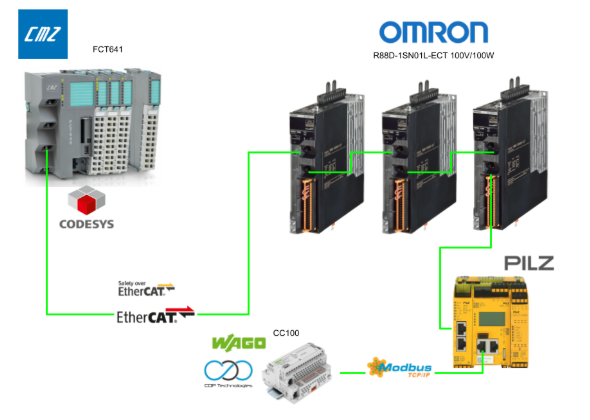
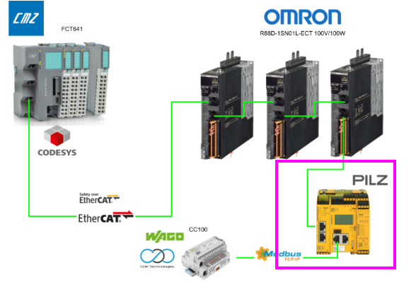
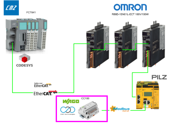
In this article, we will set up a Modbus TCP Server on the PILZ PNOZ m B1 Side to publish the FSOE status of the OMRON R88D Servo. Then, we will install the CDP Runtime on WAGO’s CC100, build a Modbus TCP Client, and access that Modbus TCP Server. We will also use the CDP Studio WEBUI.
Now, let’s enjoy FA.
Reference Link
http://soup01.com/en/category/cmz_en/
PNOZ Modbus TCP
For data exchange via Modbus/TCP, the PNOZmulti 2 acts as the server. All
service data is defined in a single data record and can be accessed directly by the client.
System requirements
To use Modbus TCP with PNOZ m B1 Side, the following minimum system requirements must be met.
- PNOZmulti Configurator: From version 9.0.0
- PNOZ m B0 + PNOZ m ES ETH
Modbus/TCP – Basics
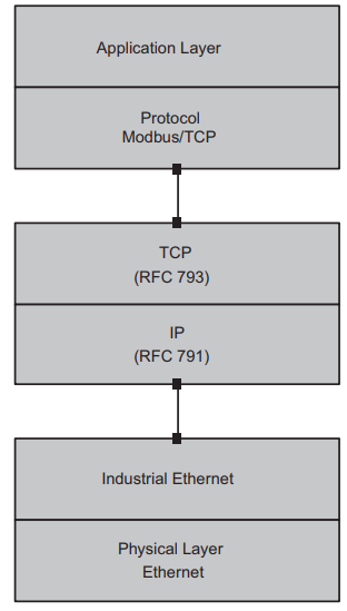
Modbus/TCP is an open fieldbus standard published by the user group MODBUS-IDA. Modbus/TCP is a protocol based on Industrial Ethernet (TCP/IP over Ethernet). It is one of the protocols for client/server communication. Data is transferred via a request/response mechanism using function codes (FC).
Modbus/TCP is connection-oriented, and before usable data can be transferred via Modbus/TCP, a connection must first be established between two Modbus/TCP interfaces.
A connection must be established between two Modbus/TCP interfaces.
The initiator of the connection is called the client. The communication partner with whom the client establishes the connection is called the server.
Modbus/TCP with PNOZmulti 2
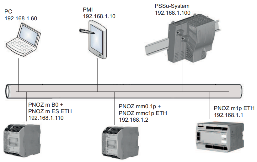
The interface for communication via Modbus/TCP is provided to the PNOZmulti 2 via the communication module PNOZ m ES ETH.
The PNOZ m ES ETH can manage up to 8 Modbus/TCP connections. The PNOZmulti 2 is always the server for the connection. The connecting client can be various devices such as a PC (PNOZmulti Configurator), control systems, or display units. These can access the concurrently configurable
PNOZmulti 2 control system.
All information polled during virtual I/O and fieldbus communication is contained in the data area. Data is accessed directly. It is no longer necessary to switch via tables/segments.
The configuration required for Modbus/TCP is already fully pre-configured in the PNOZmulti 2 operating system. All that is needed in the PNOZmulti Configurator is to activate the virtual inputs and outputs.
In the configurable PNOZmulti 2 control system, the port number “502” for data exchange via Modbus/TCP connection is fixed as the default. It is not displayed in the PNOZmulti Configurator and cannot be changed.
Data areas
The configurable PNOZmulti 2 control system supports the following Modbus/TCP data areas. Note that addressing for the PNOZmulti system starts from “0”. For devices from other manufacturers, addressing may start from “1”.
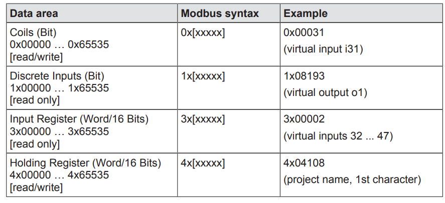
Function codes
When communicating with PNOZmulti 2 via Modbus/TCP, the following function codes (FC) can be used:
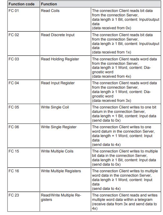
Input and output data
The following table describes the Modbus/TCP data areas containing the current status of the PNOZmulti 2 virtual inputs. These are user-configurable virtual inputs. Relevant areas for data are defined in each Modbus/TCP data area (Coils (0x), Discrete Inputs (1x), Input Registers (3x), Holding Registers (4x)). Read/write access depends on the Modbus/TCP data area.
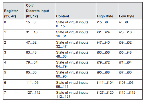
The following table describes the Modbus/TCP data areas containing the status of the PNOZmulti 2 virtual outputs. Relevant areas for data are defined in the Modbus/TCP data areas Discrete Inputs (1x) and Input Registers (3x). Read access is possible for these data areas.
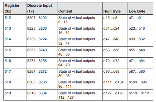
Implementation
PNOZ Side
First, we will build the PILZ Pnoz Controller side.
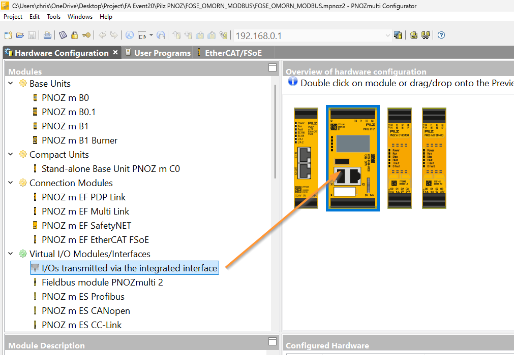
Add Virtual Interface
To use MODBUS TCP communication for the PNOZ Mult controller, add Virtual I/O >> Modules/Interfaces from the project in the PNOZmulti Configurator.
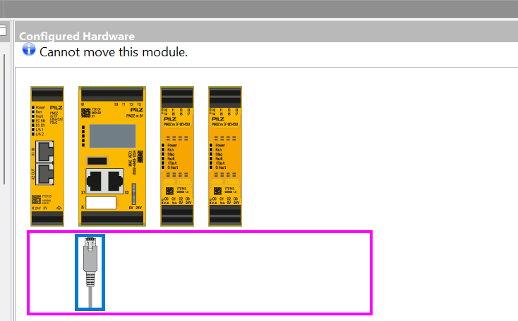
Done!
Next, let’s change the Modbus TCP Interface to an easy-to-understand name.
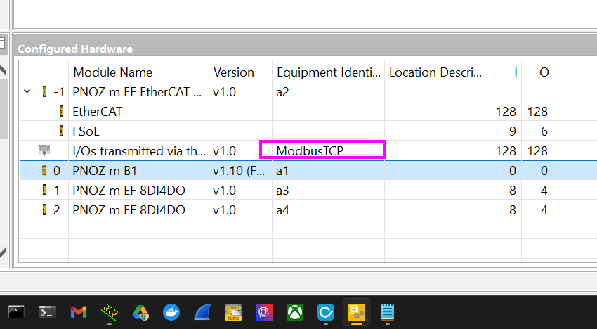
Program
Next, we will create the program for the PNOZ small controller.
Main Program – Page1
First, open Main Program > Page 1.
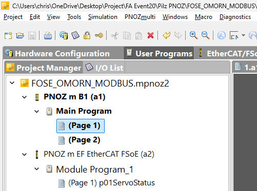
This is the program for Page 1.
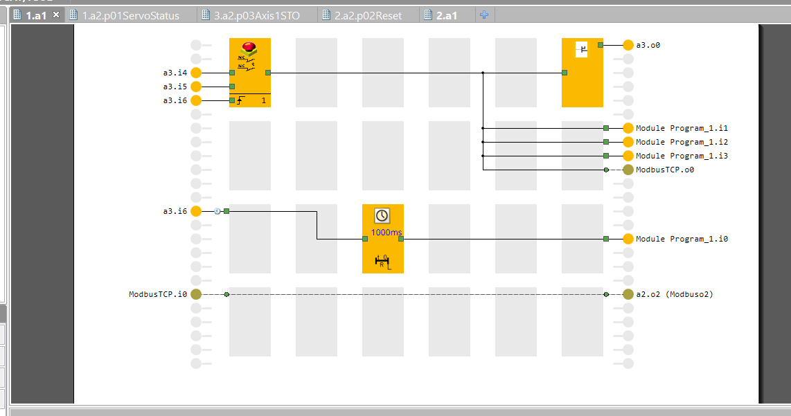
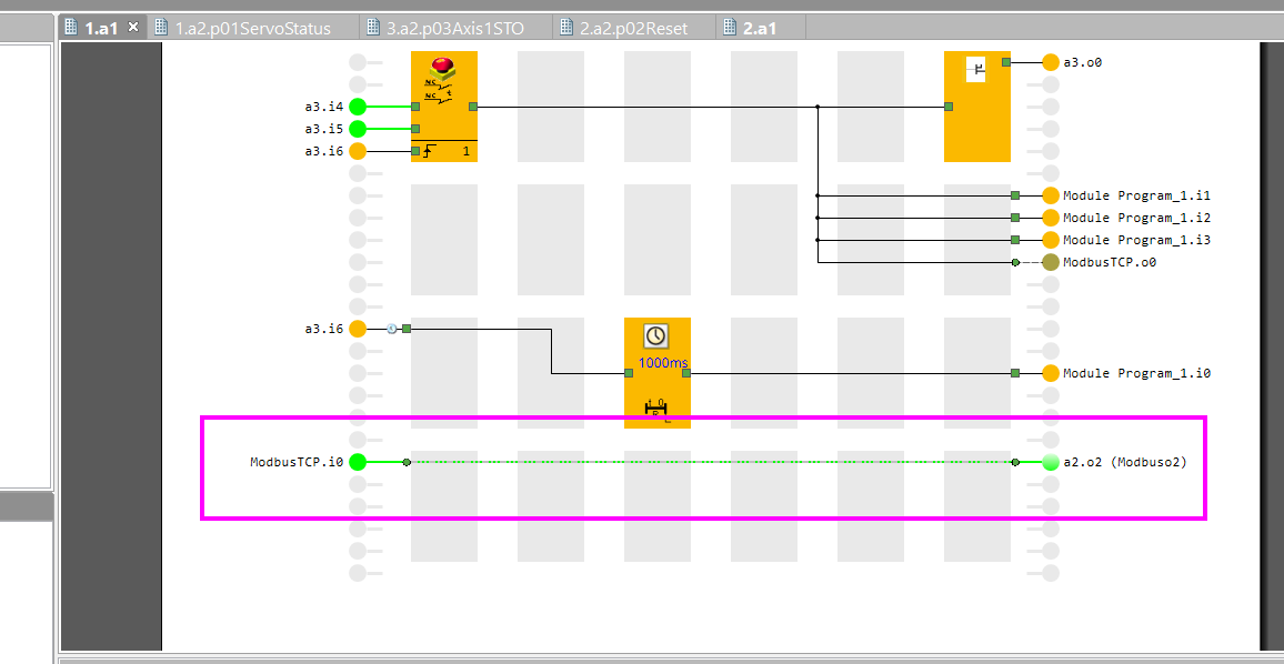
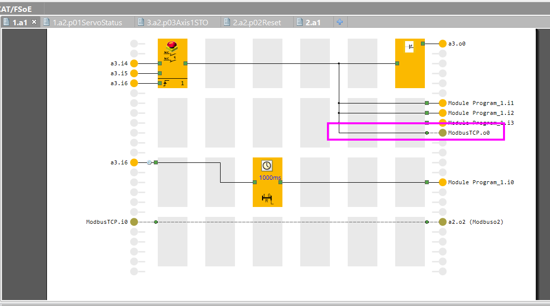
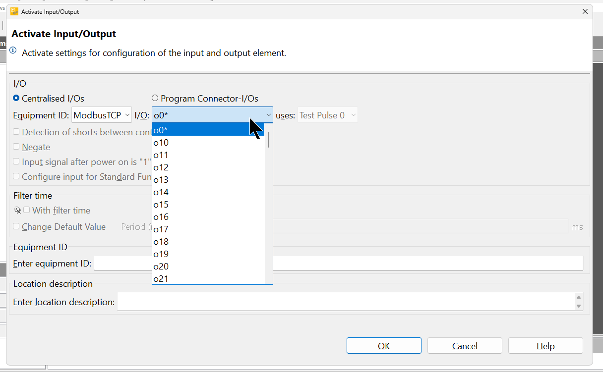
First, the emergency stop status is connected to Modbus TCP virtual output number 0.
Set the Virtual Interface added earlier in Equipment ID.
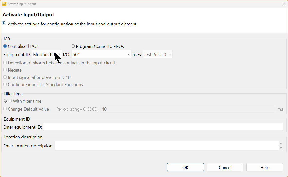
For I/O, you can set the virtual output number.
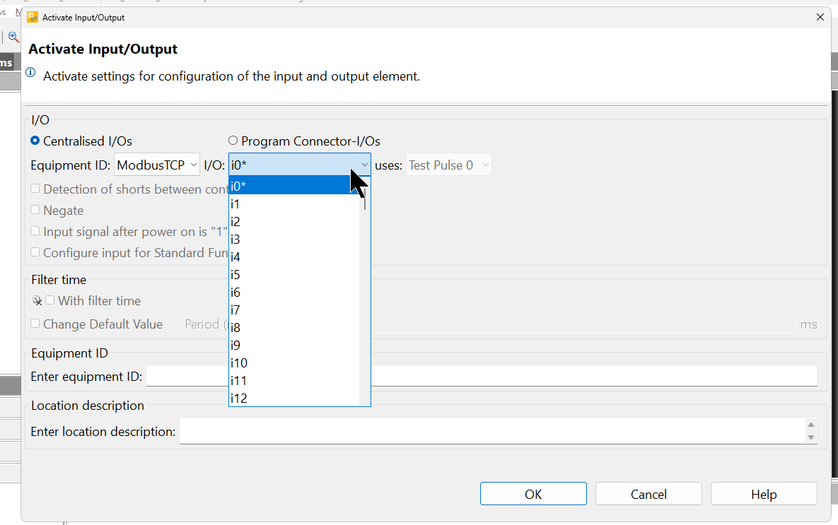
Next, since we also want to receive signals from the Modbus TCP Client, add a virtual input.
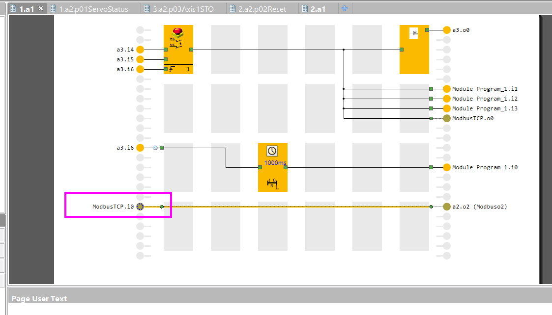
Set the virtual input number for the I/O.
Main Program – Page2
Next, create the program sheet 2, Page 2, for the Main Program.
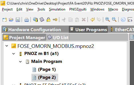
Connect the FSOE status of each OMRON R88D SERVO to the MODBUS TCP virtual outputs.
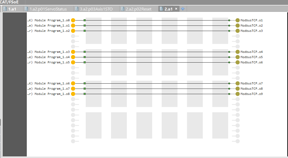
CDP Studio
Next, we will build the CDP Studio side. This time, the CDP Studio Runtime will be installed on WAGO’s CC100.
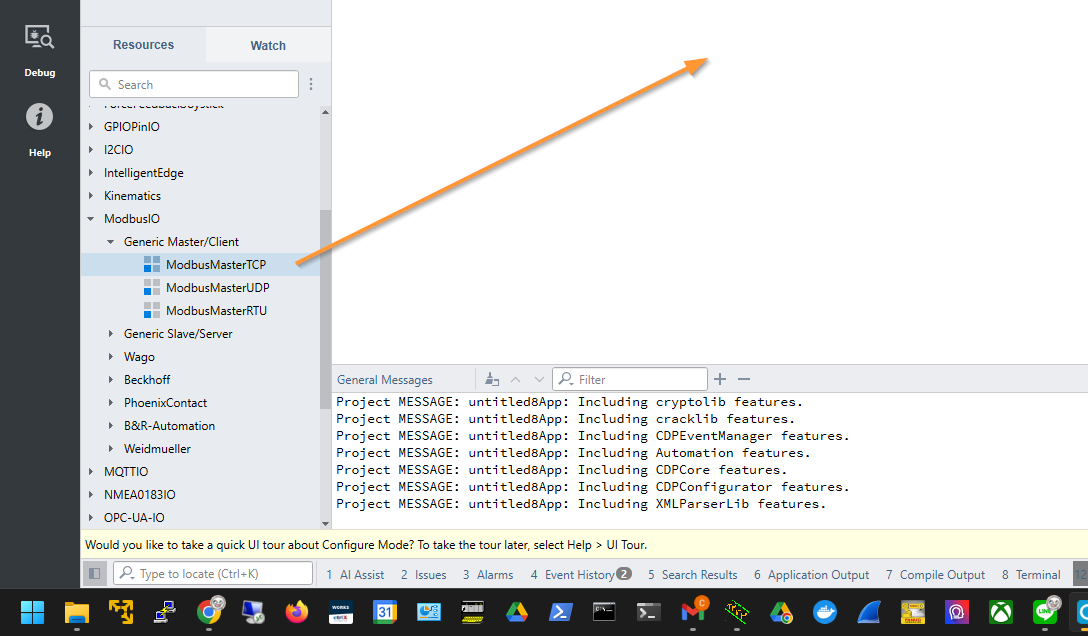
Add Modbus TCP
To add the Modbus TCP Client to the project, drop ModbusIO > Generic Master/Client > ModbusMasterTCP. This block is for operating as a Modbus TCP Client.
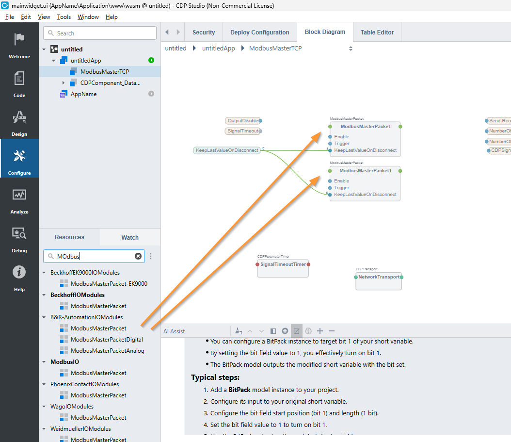
Add ModbusMaster Packet
Open the ModbusMasterTCP block and add two ModbusMaster Packet blocks. These blocks perform the connection settings for the corresponding ModbusMaster. One block corresponds to one setting.
- FC Code
- Register Number
- Number of Registers
And so on.
Click on the ModbusMasterPacket block and open Properties.
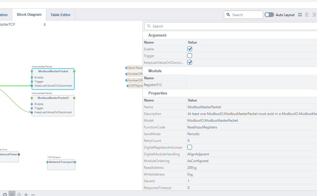
Read Input Register
For the first ModbusMasterPacket, since we want to read Input Registers, set FunctionCode to ReadInputRegisters.
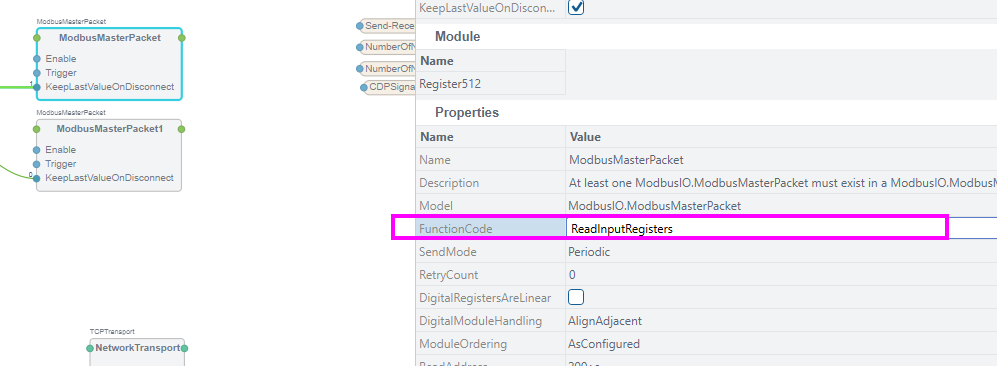
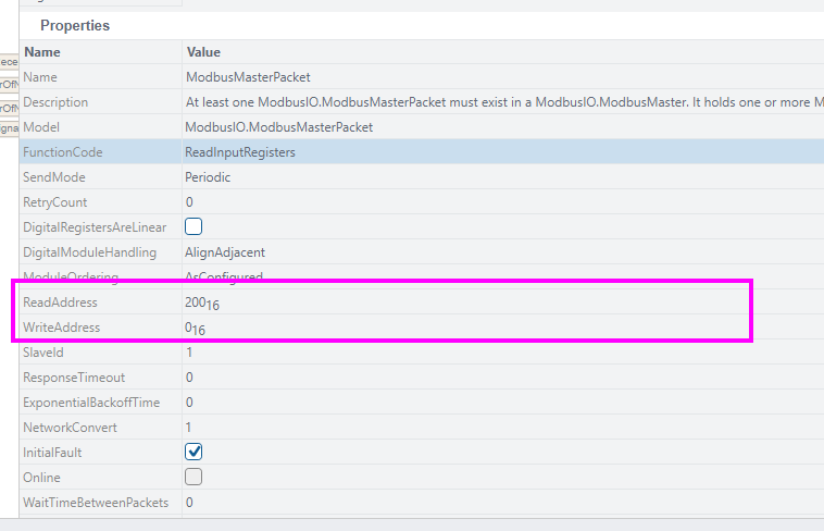
ReadAddress and WriteAddress are the access register OFFSET for the corresponding ModbusMasterPacket. Note that the setting in this field is in hexadecimal.
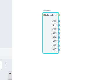
Open the ModbusMasterPacket added earlier and add 8-AI-short.
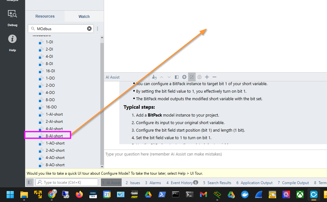
Done! Since one register is one word, this block will access 8 consecutive words. Since ReadInputRegisters was set to 200F earlier, this block will access Input Registers 200-207.
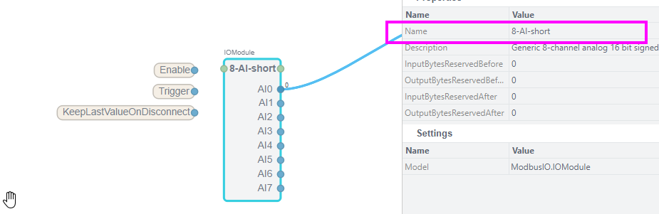
If you want to change the block name, do it in Name.
Write Multiple Register
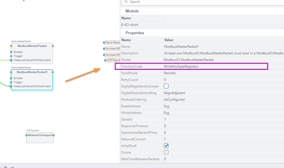
Open the Properties of the other ModbusMasterPacket block and set FunctionCode to WriteMultipleRegisters.
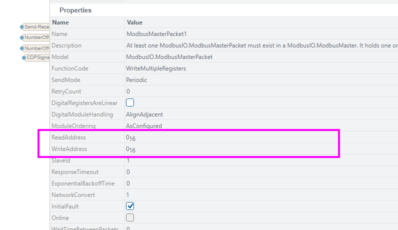
Set WriteAddress to 0. This is because the Modbus virtual inputs of PNOZ m B1 start from Modbus Register 0.
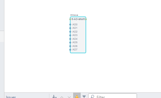
Open ModbusMasterPacket and add WriteMultipleRegisters.
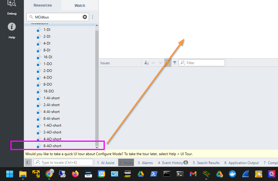
Since the number is for an 8-AO Short block, it will write to Registers 0-7.
Add HMI Apps
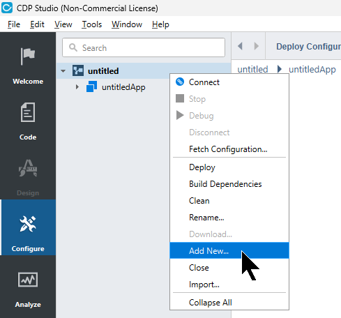
This time, we will add an HMI application to CPD Studio. That application will also run on the CC100. Right-click on the project and select Add New.
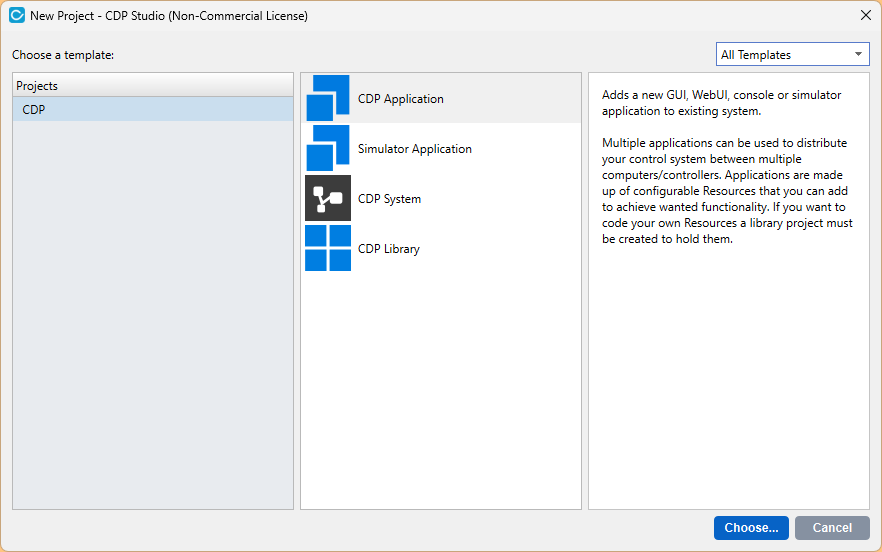
Select CDP Application and proceed with Choose.
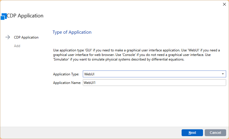
Select WebUI as the Application Type.
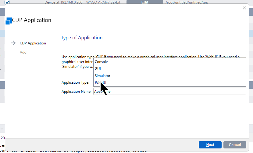
Enter the application name and proceed with Next.
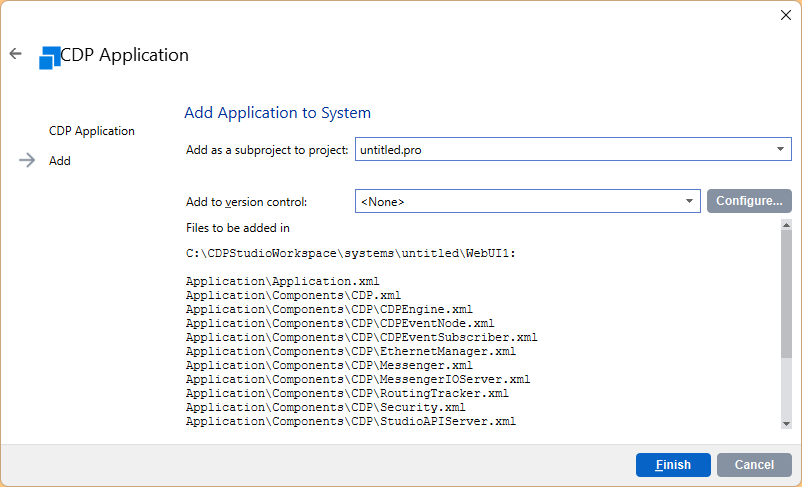
Create the project with Finish.
Done!
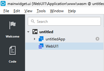
Click on Design to proceed to the WebUI creation screen.
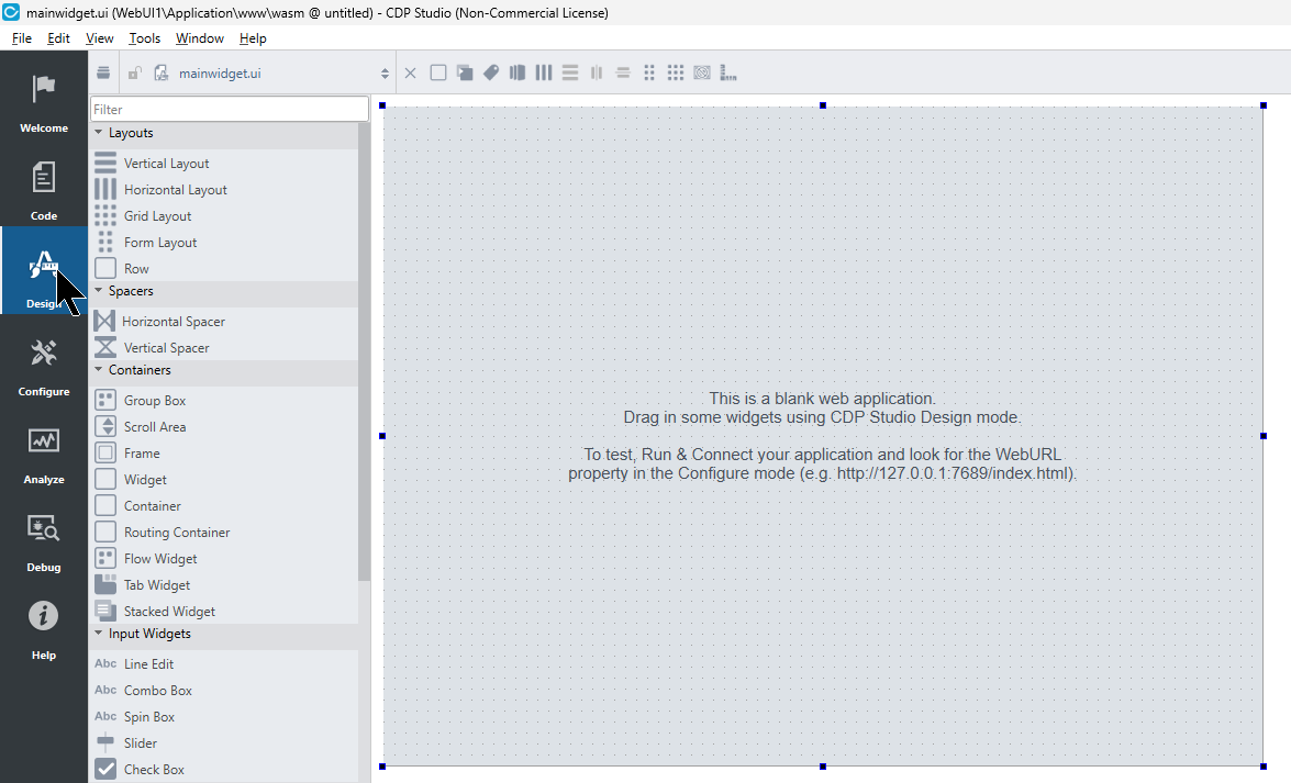
Add Container
Creating a WebUI is slightly different from a GUI application; you first need to add a Container to the screen.
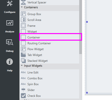
Configure Screen
This is the screen created in this article.
- Emergency stop status
- Safety status of the 3 OMRON R88D axes
- Button to turn ON/OFF Modbus virtual input 0 of PNOZ m B1 Side
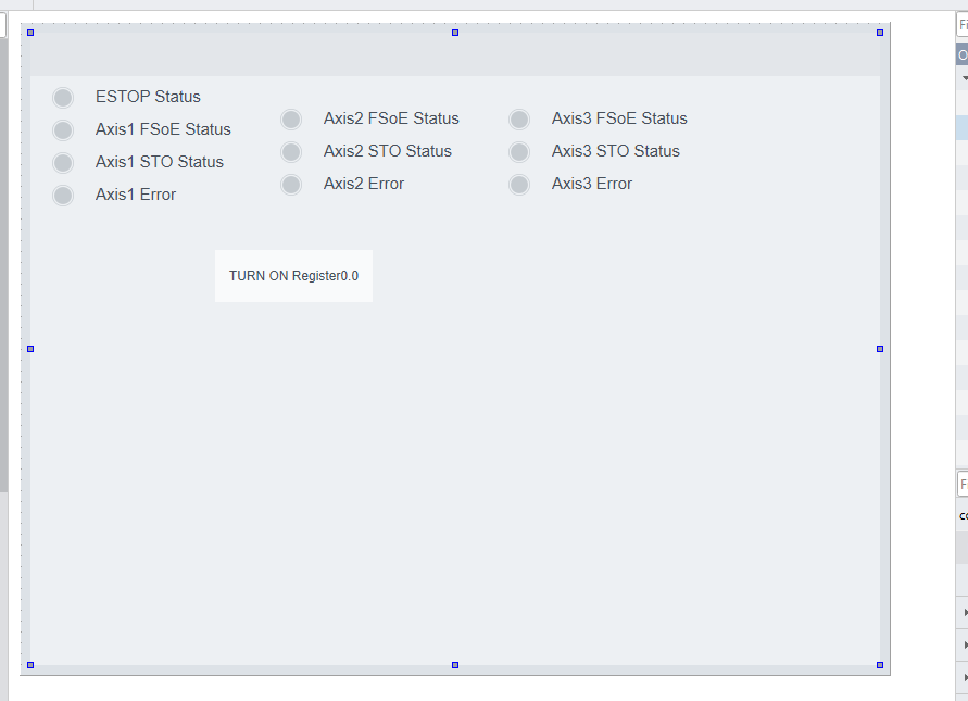
Add CDP Container
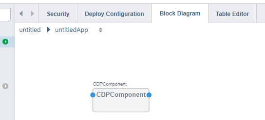
After creating the WebUI, create the signals that connect to it. Add CDPCore > CDPComponent.
Done!
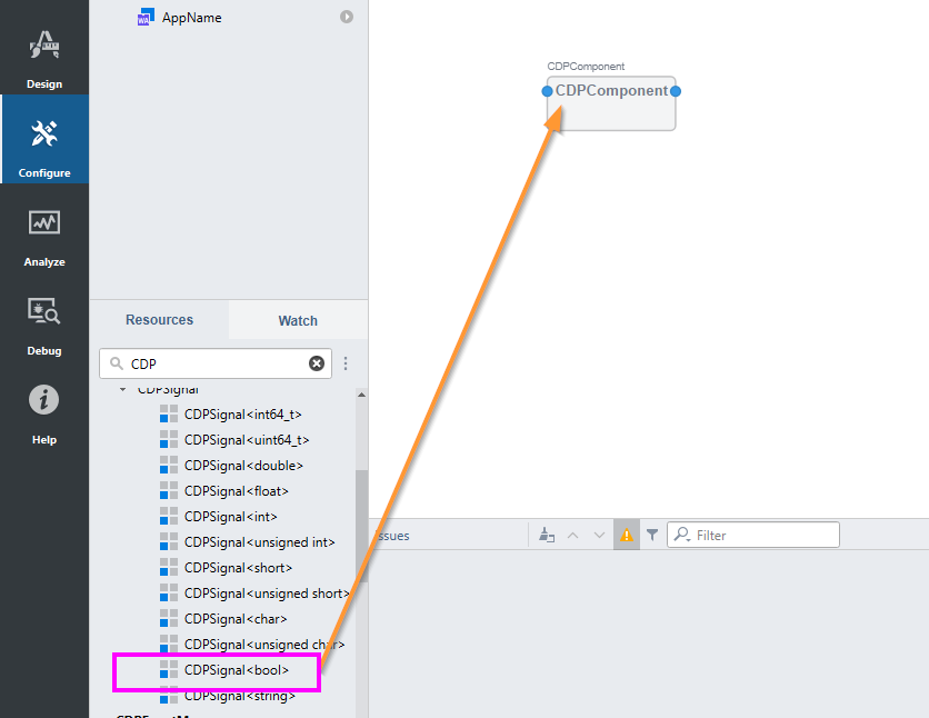
Since we want to increase the input/output signals in the CDPComponent, drop CDPSignal<bool> from Resources into the CDPComponent.
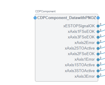
Done!
Bit Extract
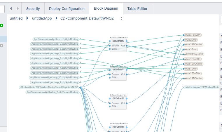
Use the Bit Extract function to specify and output a Bit at a certain position in a 16-bit word variable.
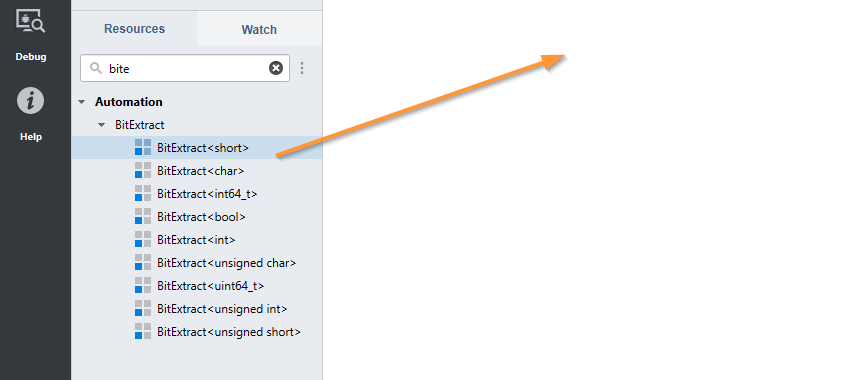
This is the BitExtract block.
- Source: Input
- BitNo: Bit position to extract from the Source word (calculated from 0)
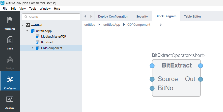
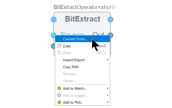
Right-click the Source parameter > click Connect From to connect with a variable.
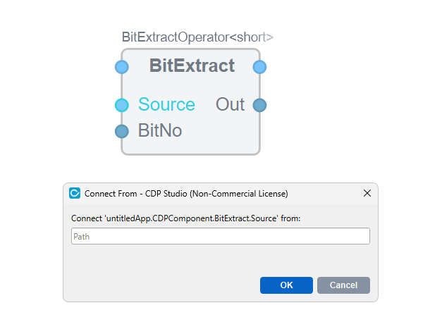
The Path setting screen will appear; connect with AI1… of the 8-AI block added to the ModbusMasterPacket earlier.
Done!
Bit Pack
Next, use the Bit Pack block to turn ON/OFF specified Bits of a word variable.
- Source: Word variable source
- BitNo: Bit position to access
- Out: Calculation result
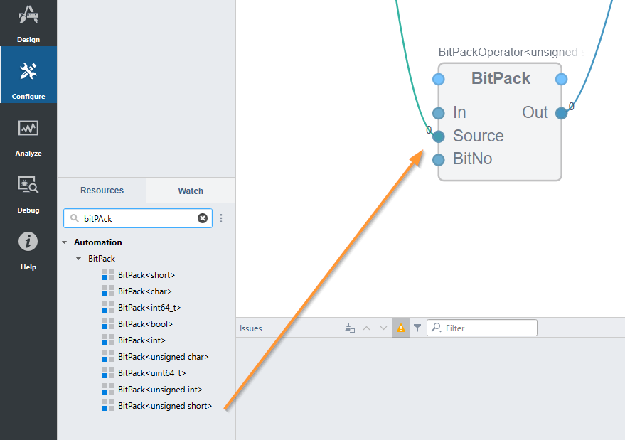
Map Write Register
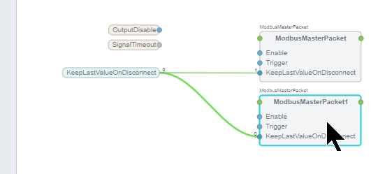
Since we want to connect with the BitPack function from earlier, open ModbusMasterPacket1 (for WriteMultipleRegisters).
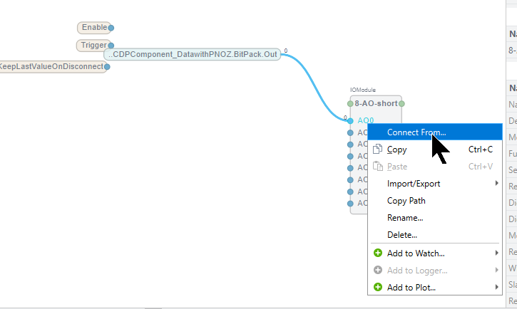
In this article, since we want to write data to a virtual input, right-click AO0 > click Connect From > connect with the output of the BitPack function from earlier.
Deloy
Finally, download the program and WEBUI project to the CC100.
Result
Done! The necessary applications have been downloaded to the CC100.
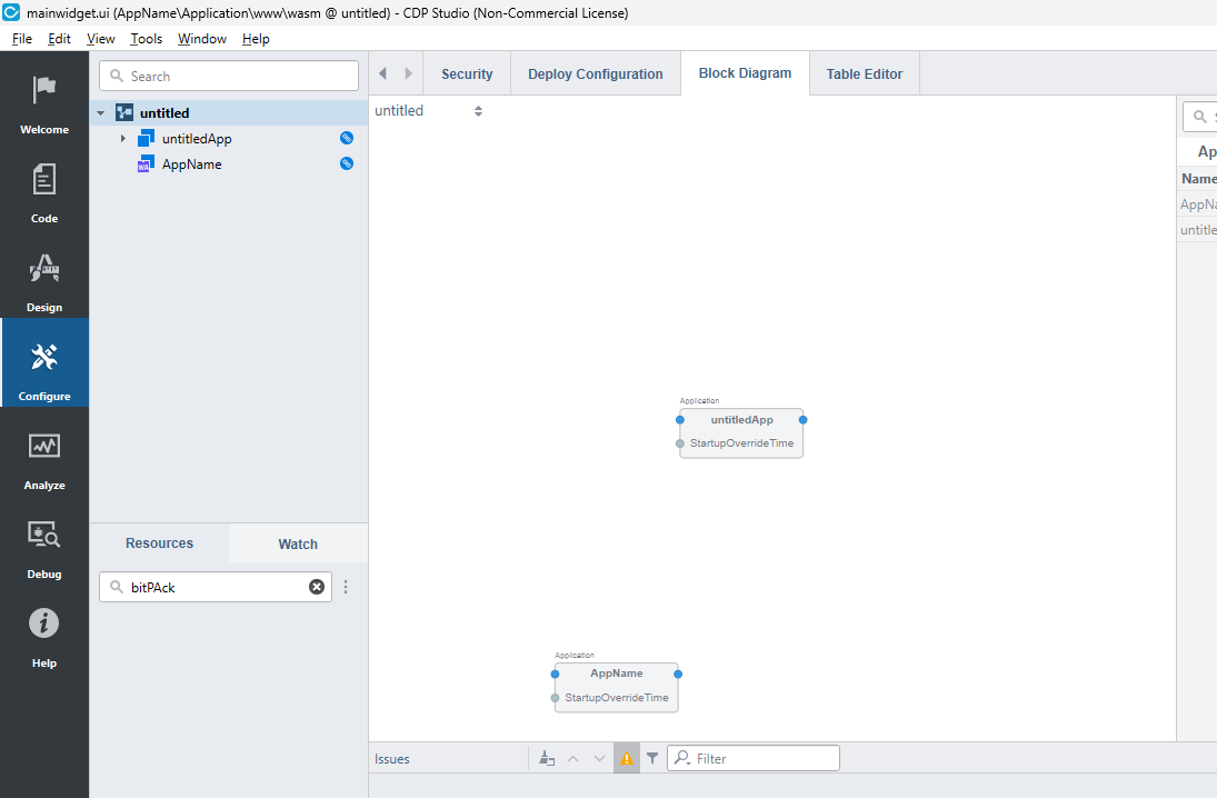
Access the link below (change the IP address to the address of your CC100).
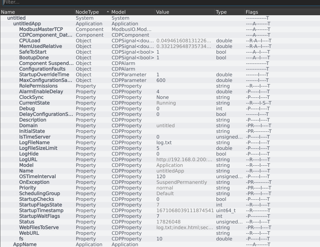
You can check the internal variables and status of the CDP Studio Runtime on a Web Browser.
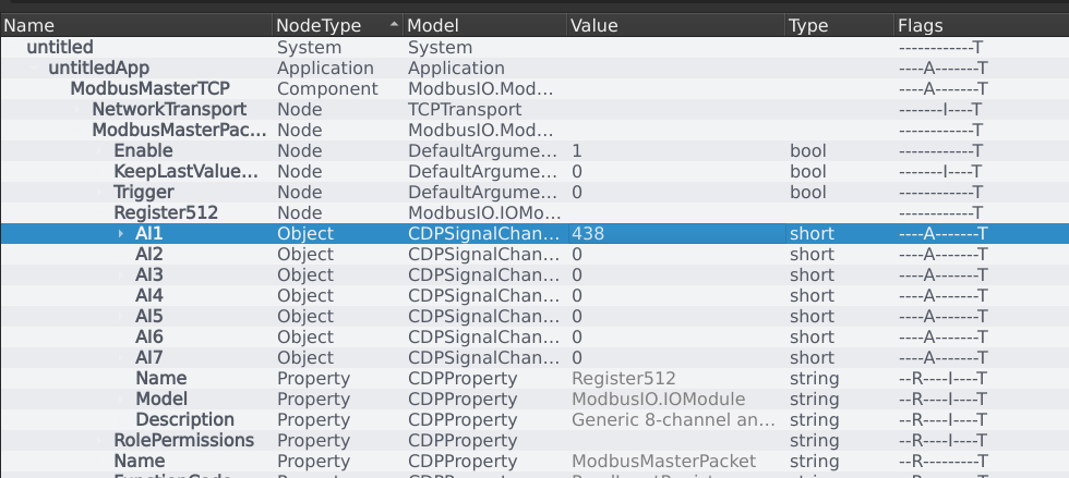
For example, you can directly check the current values of the ModbusMasterPacket register reads.
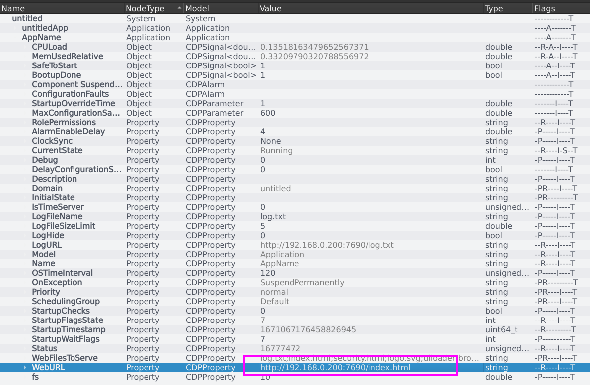
To check the WEBUI URL, the current value of the WebURL variable in the WEBUI application will be the WebUI URL.
Done! With the combination of CDP Studio Runtime and CC100, the status of the PNOZ m B1 Side controller was successfully retrieved via Modbus.
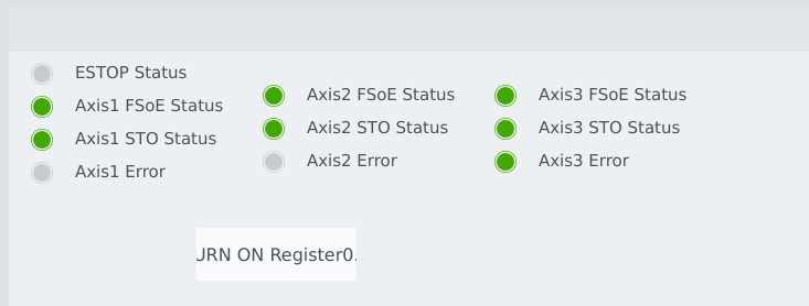
Additionally, it was confirmed that pressing a button in the WEBUI allowed the PNOZ m B1 Side to receive the signal.