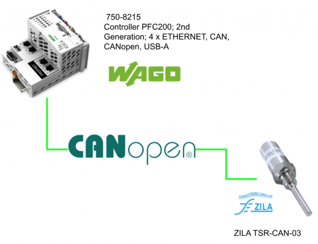
In this tutorial, I will show you how to use 750-8215 to start up a CANOPEN master and communicate with a canopen support sensor that made by ZILA.Hope you like this.
Youtube Video
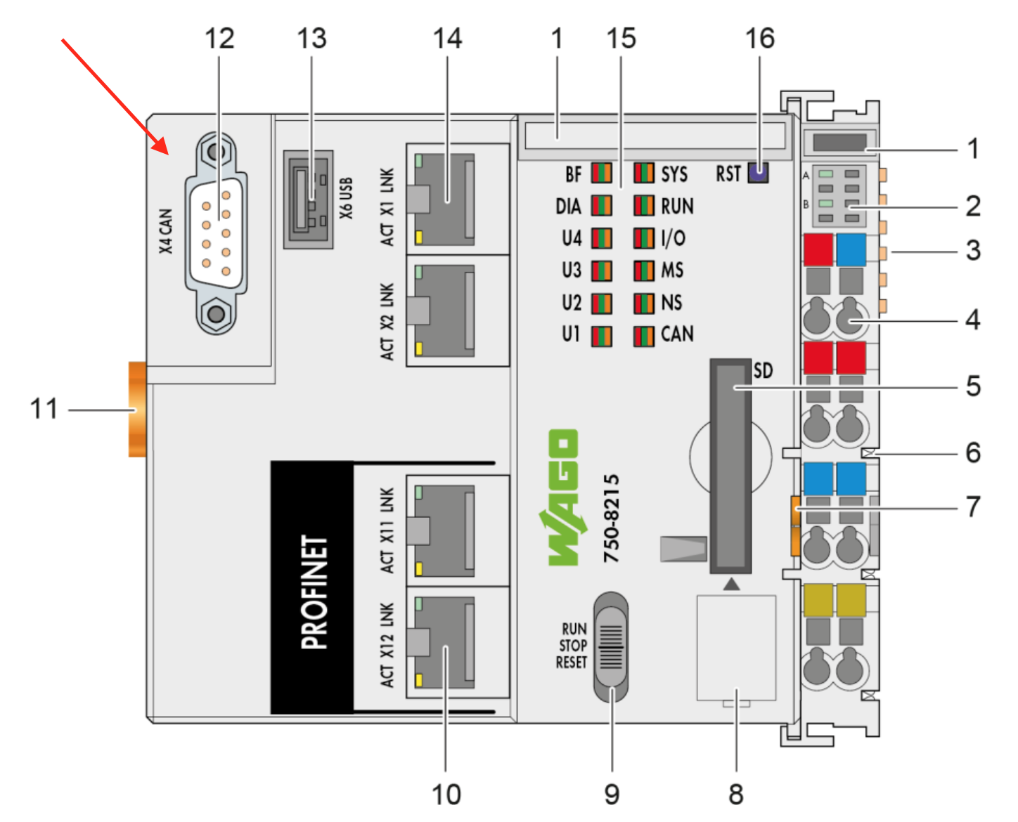
Wago 750-8215 CAN Interface
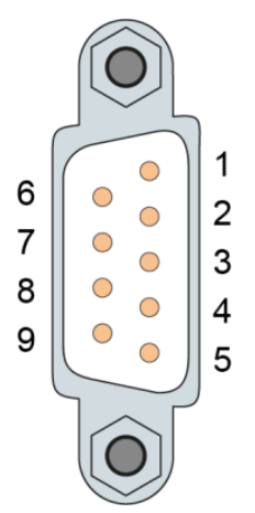
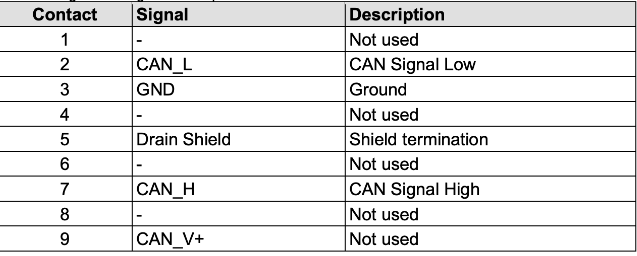
The X4 9 Male Pin is used for the CANOPEN master.
X4 Pin Assignment
Here is the Pin assignment,
Resistor
Please install an 124 Ohm resistor at the end of both side.

LED-CAN
There is a CAN LED for showing the CANBus status.Red=Error,Green is Bus running, off=Bus is not enabled.

Proess IO Max
The Max of Process is 2000 words.
CANOPEN?
Reference to Wiki;
https://en.wikipedia.org/wiki/CANopen
CANopen is a communication protocol and device profile specification for embedded systems used in automation. In terms of the OSI model, CANopen implements the layers above and including the network layer. The CANopen standard consists of an addressing scheme, several small communication protocols and an application layer defined by a device profile.

Version
CANOPEN has CAN2.0A and CAN2.0B, and Now CAN FD is released.
- CAN2.0A can be configured with11Bit Node ID,8 Bytes data and Transmission speed up to 1Mbps.
- CAN2.0B can be configured with 11/29 Bit Node ID,8 Bytes data and Transmission speed up to 1Mbps.
- CAN2.0A can be configured with 11/29 Bit Node ID,64 Bytes data and Transmission speed up to 10Mbps+.
Please confirm which version of CANOPEN Protocol is supported by your Node.
And Currently there are some industrial protocols that are based on CAN – For Example Devicenet,CANOPEN,CANOPEN FD etc..
Data Definition
CAN data can be defined as Bit or Byte as Little Endian.And here is some data type that CAN data supported:
- UNSIGNED8・UNSIGNED16・UNSIGNED32
- INTEGER8・INTEGER16・INTEGER32
- FLOAT・TIME・STRING
- etc..
Data Addressing
Now we can have an introduction of the CANOPEN addressing concept. you can imagine CANOPEN is using a look-up table like excel. A 16 bit index,8bit SubIndex and 24 bit data are included in each index entry, and the index range will represent the usage of your entry.
- From 1000h – CANOPEN parameters
- From 2000h – Specific from manufacturer
- From 6000h – Defined from Device Profile
We can image the Excel table just like below:
| Index | Sub-Index | Data Type | Description |
| 1000h | 0 | UNSIGNED32 | Device Type |
| 1001h | 0 | UNSIGNED8 | Error Regisiter |
| … | |||
| 1008h | 0 | UNSIGNED8 | =4,the numbers of sub index items of this index |
| 1008h | 1 | UNSIGNED32 | Vendor ID |
| 1008h | 2 | UNSIGNED32 | Device Code |
| 1008h | 3 | UNSIGNED32 | Revision Number |
| 1008h | 4 | UNSIGNED32 | Serial Number |
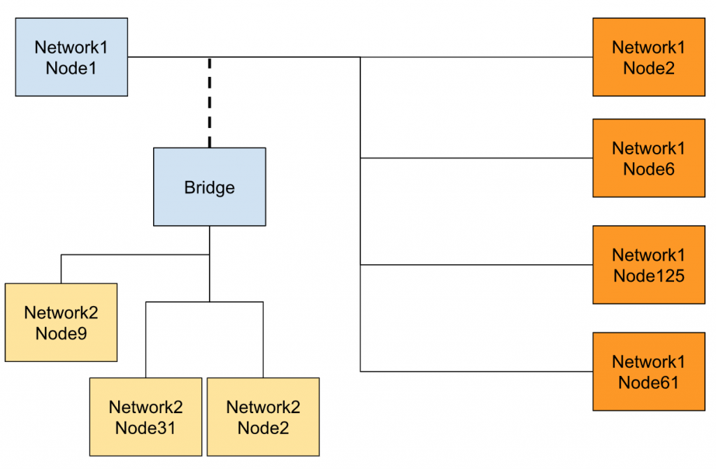
Nodes & Network
The max Node of CANOPEN is 127 and can not be duplicated.
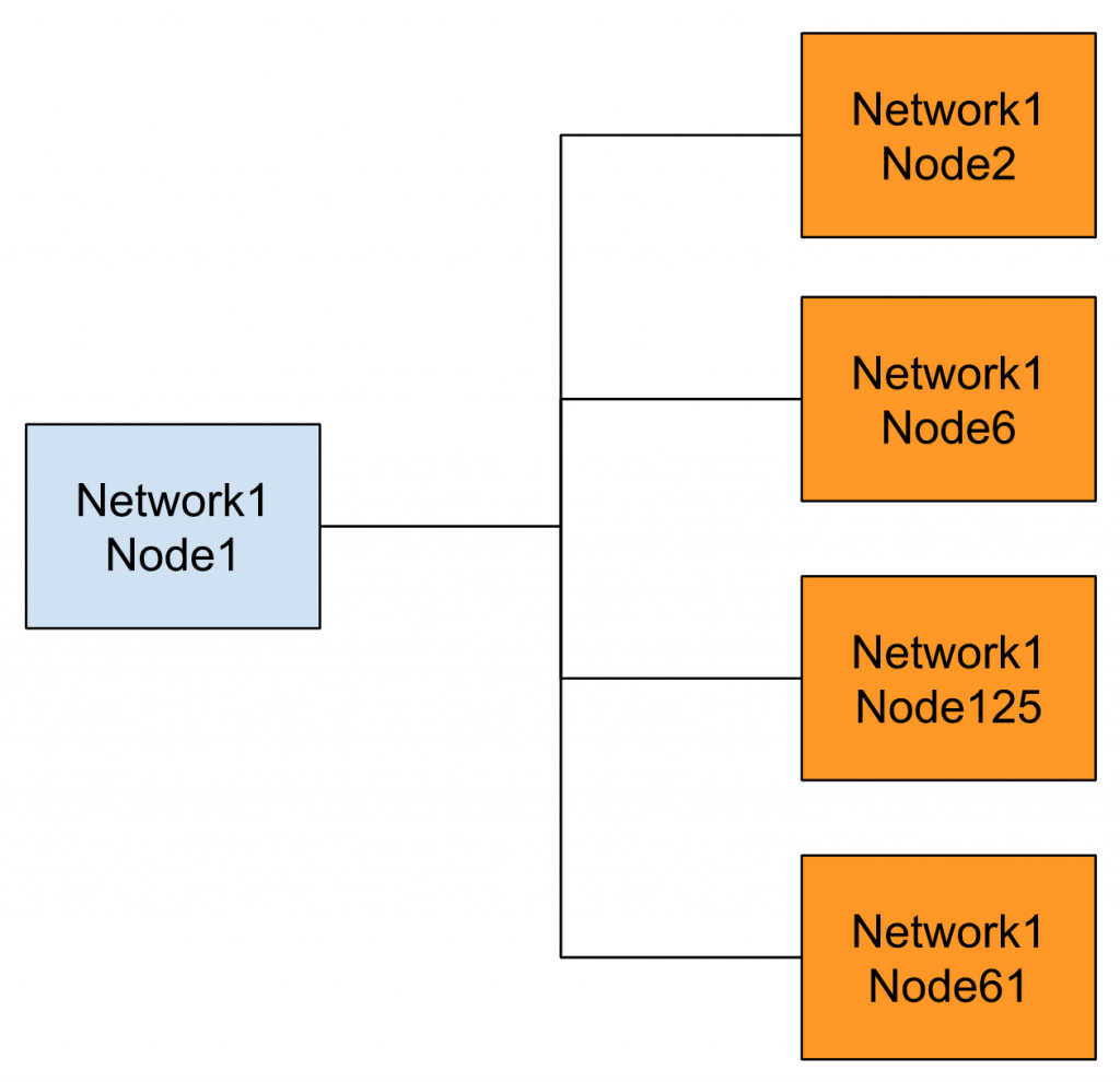
You can also use a bridge or gateway to extend the network up to 255.
Network Management
CANOPEN can get all the information of the node inside your network.for example,
- Boostup
- It is a message that is sent to the master while the node is powered on or reset.
- Heatbeat Message
- Emergericies
Then the CAN master can reset or change the state of the node.
Service & Data Access Protocol
CANOPEN provides a couples method for the user to access the data or operate some services.
- SDO/USDO(Service Data Object/Universal Data Object)
- all the parameters inside the node can be accessed by SDO.
- Base on Request and Response
- Node diagnose
- Node configuration
- PDO(Process Data Object)
- Get the optimization data model.
- The request can be triggered by cyclic, event or change.
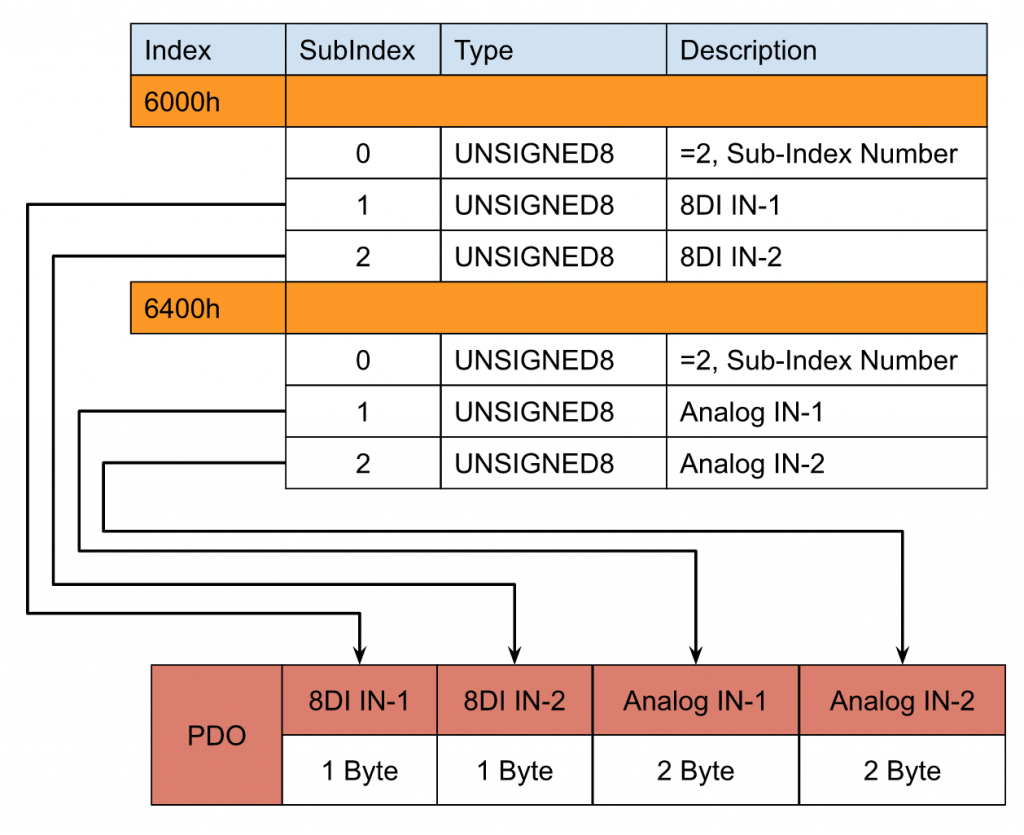
Process Data Object(PDO)
In this tutorial we only use PDO, I will explain a little more about this.PDO is an object that allows the user to access a couple of Dictionary Entries at the same time and group as a message.There is only byte data inside the telegram.
for example,
- Byte0 is an Index 6000h, SubIndex1 with 8 digital inputs in channel 1.
- Byte1 is an Index 6000h, SubIndex2 with 8 digital inputs in channel 2.
- Byte2-3 is index 6400h, Subindex 1 with analog input channel1.
- Byte4-5 is index 6400h, Subindex 2 with analog input channel2.
Finally the node will group these Dictionary Entries into one telegram and send them to the master.
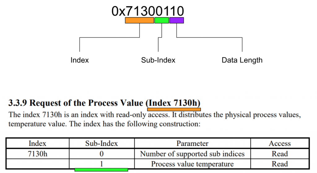
If you still can not image the PDO mapping , you can image that is a pointer in the programming language.The structure of this pointer is
- 16Bit Index
- 8Bit Subindex
- 8Bit Data Length
As I mentioned before, if we open the eds file of the sensor from ZILA ,the default value of PDO 1A00Sub1 is 0x71300110.
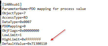
0x71300110h , 0x7139 is the index , 01 is the Subindex,10 is the Data length (16 in decimal),
Let we summary it.
| TPDO | RPDO |
| Transit PDO | Receive PDO |
| TPDO 1-512 | RPDO 1-512 |
| SubIndex0=MappedされたEntries数 | SubIndex0=the number of subindex |
| SubIndex1-n=ItemのIndex | SubIndex1-n=Item’sIndex |
Profies Available
A very big advantage that using the CANOPEN is devic profile supported.The Device profile file is described all the parameters and data are needed for communication.for example,
- CiA401 Generic I/O
- CiA402 Drives And Motion Control
- CiA406 Econder
Summary
Let’s make a summary now.CAN/CAN FD can only use their advantage with the higher layer implementation – And that is why we have CANOPEN/DeviceNet/J1939…etc.
There Are PDO and SDO objects in CANOPEN,
SDO is a max 4 bytes request and 8 Byte Segment.
PDO is max 8 bytes.
Finally, CANOPEN is a communication protocol; the nodes can not be duplicated.
Device and Application profiles are supported.
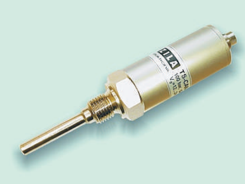
ZILA Sesnor Side
This is the Sensor that was used in my tutorial – A Temperature sensor from ZILA, a Gemeray Company with CANopen2.0A Support, from -40 to +80 °C,
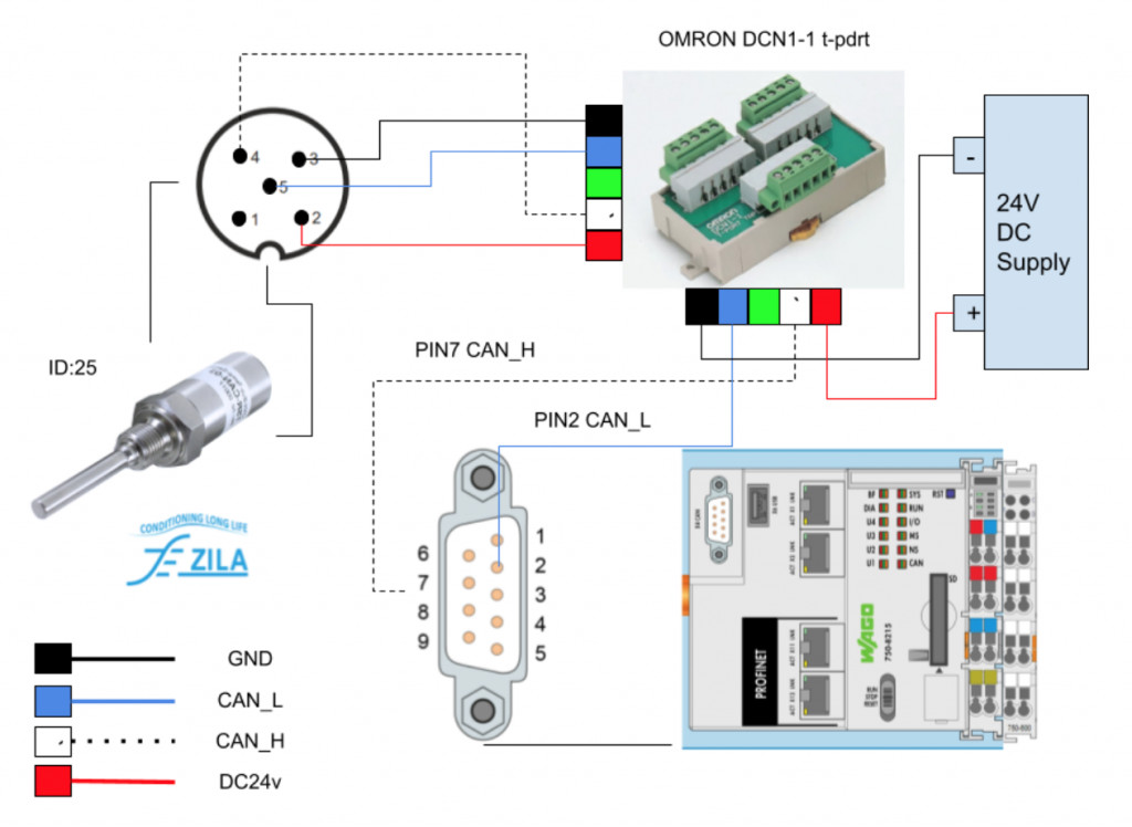
Pin assignment
Here is the Pin assignment of the Sensor(View From Sensor).

| Pin | Description |
| 1 | Program pin and do not use it. |
| 2 | Operate Voltage 24v DC |
| 3 | GND/CAN_GND |
| 4 | CAN_H |
| 5 | CAN_L |
PDO Mapping

Byte 0-1 temperature measurement
Byte0(LSD) and Byte2(MSB) are combined as Temperature measurements.
For Example, the current temperature is 24.2 if 00F2 is received(242 in decimal ,with 1 float point)
Byte2-3Not Used
Byte2 and Byte3 are not used and always 0.
Byte4-5AD Value
Byte4(LSD) and Byte5(MSB) are combined as Analog measurement values.
Byte6-SDO object 6600h alarm status
0=not alarm,1=Alarm is activated.
Byte7-SDO object 1001h Error Register
| Bit | Error | Description |
| 0 | Generic Error | Hardware defeat |
| 1 | EEPROM Error | data can not be written in the EEPROM of CAN Sensor(Hardware defeat) |
| 4 | Communication Error | Communication Error |
| 5 | Alarm Error | PV is over the alarm setting |
E!COCKPIT Version

Implemenation
Wiring
Here is the wiring diagram.
Configration
Now I will show you how to use E!COCKPIT to configure the CANOPEN Network and program.
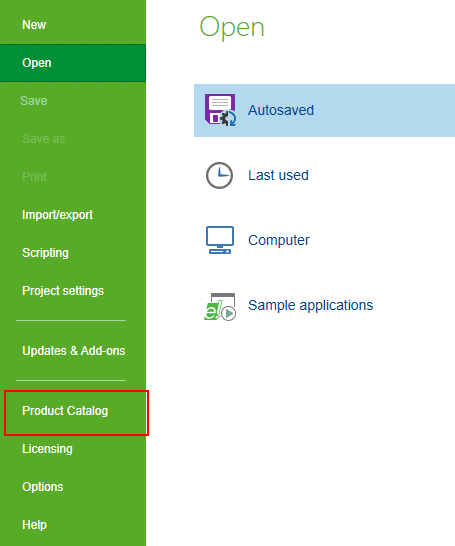
Import EDS
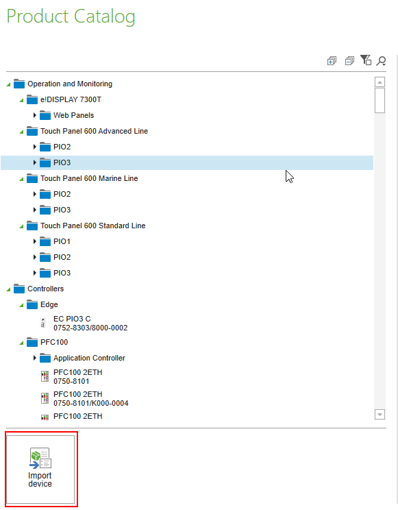
Click the Product Catalog button.
Click the Import Device Button.
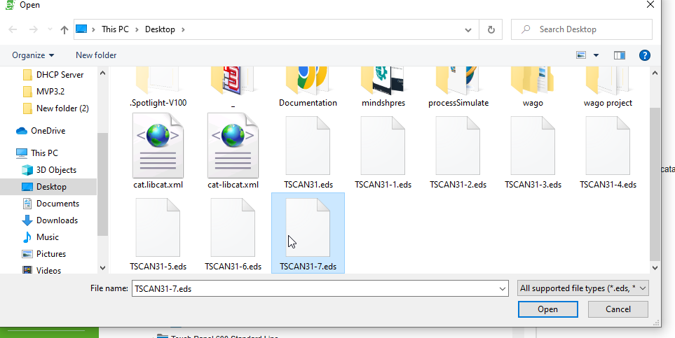
Choose the EDS File and Open it to import into your IDE.
Scan Your CPU
NETWORK>Setting to configure the scan parameters.
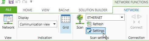
And confirm whether these parameters are correct or not.

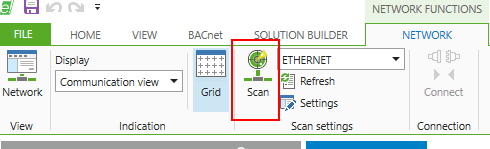
Go to NETWORK>Scan to search the CPU.
Please wait a second..
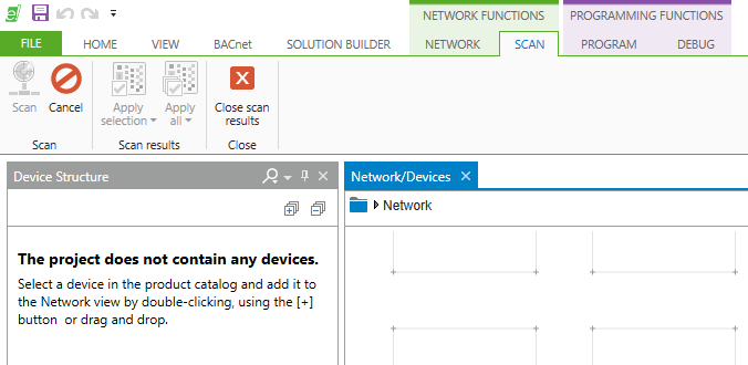
Press Apply all to get the data from the scan data to your project.

Insert the CANBus Sensor
On the Right Side of E!COCKPIT, you can directly drop the Devices from the Catalog to your current project and configure it.
Enter “CAN” in the search field>select the CANOPEN sensor TSL-CAN-03 and drop it to your project.
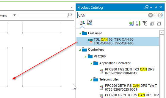
please wait a second..

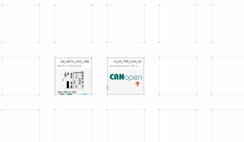
TSL-CAN-03 is inserted in your project.

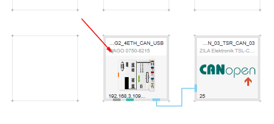
Connect to the CPU
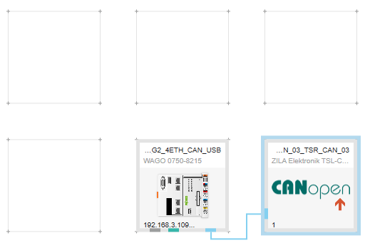
Now we can connect the TSL-CAN-03 Node to your Wago PLC 750-8215 CPU.

You only need to do it just like below.
The CANOpen network is built.
Node Setup
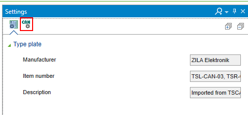
Right Click the node and press the Settings to configure your Node.

The Settings screen is shown on the right side.

Click the CAN Icon.
Node ID
Please enter the Node ID that is matched to your CANOPEN Sensor.
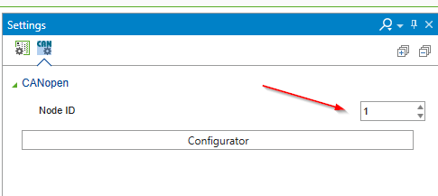
Configurator
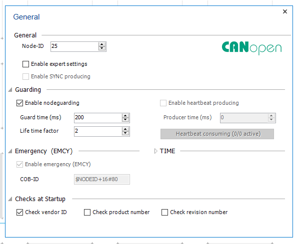
But we can do the advanced settings by Start up the Configurator.

For Example you can set the Guard Time or Check Vendor ID Options,etc.
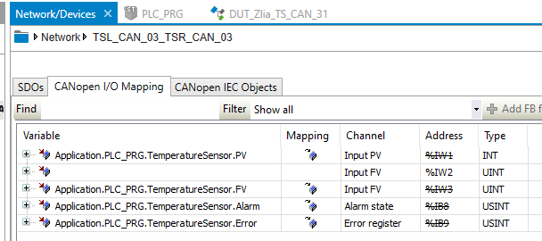
Mapping
After the basic settings are finished , we can double Click the following Node to configure the Mapping.

You can add the SDOs and configure the PDO Mapping here.
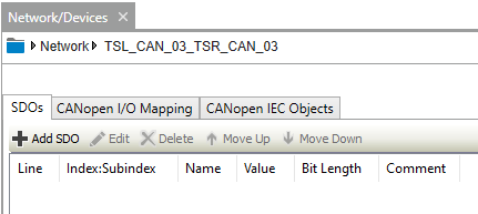
Variables in the user program can be assigned in the CANopen I/O Mapping Tab.

Create Variable
Let’s create some variables for PDO Mappings.
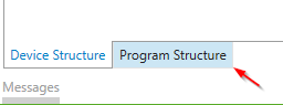
Right>Click DUT to create the Data Unit Type.(It is not necessary but just my programming style).

Enter the DUT name and “Add” it.
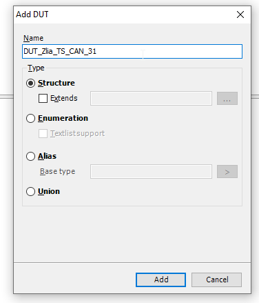
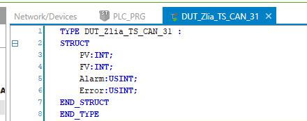
Define these Variables that are matched from the above part.(PV/FV/Alarm/Error)
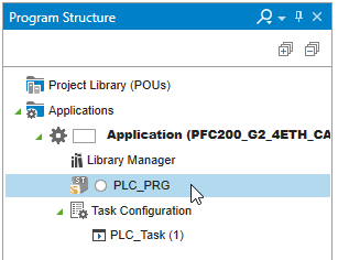
Program
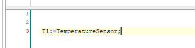
Then we can start to create the user program.
Define 2 variables with the same DUT inside your program.

And then take a Transfer logic in the User program.
Link it
Finally, please link these variables to the CANopen I/O Mapping.
Master Setup
After the mapping is finished, we can configure the Master Side of the wago CPU. Please double click the CPU.
Basic
Click the CAN ICON and choose the Baud rate.

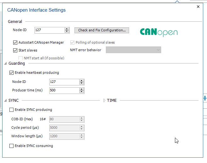
Interface Settings
Click the Interface Setting button to have advanced settings.
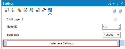
Some detail settings like Max Node-ID,Producer time can be configured in it.
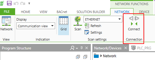
Download
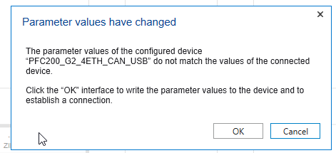
Now we can Download the project to your CPU in NETWORK Tab>Connect.
Press “OK” if an existing project is inside your project.
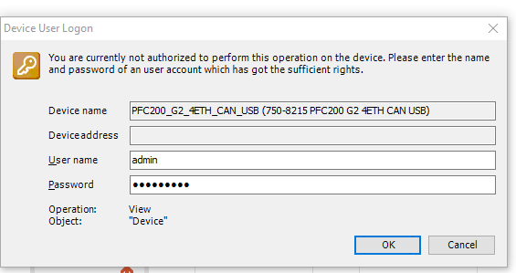
Please wait a second..

Enter your username and password>OK.
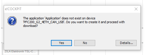
YES.
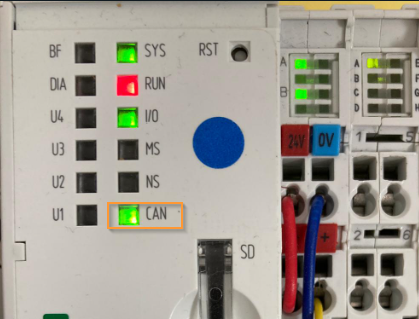
The CAN LED on your CPU is changed to Green.
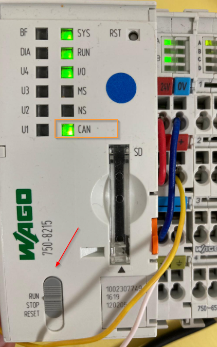
Run it
Finally Press the Run button to change the CPU status to RUN.
Result
The PV/FV values are returned from the CAN Open sensor.
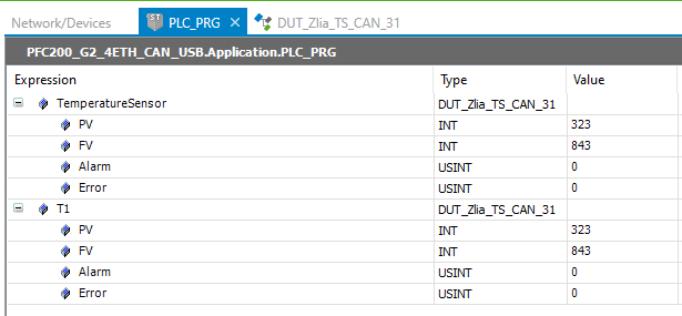
And the PV and FV will be increased if I grasp the temperature sensor.
