This is the Third episode of the Visual Components Tutorial. This time we will introduce the robot Path generation. Let’s get started!
Your Target
At the end of this Tutorial, your robot can also generate the moving Path just like this.
Reference Link
Start your Application!
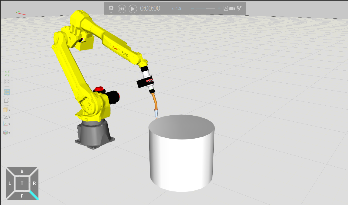
This is the Layout for this project.
Add Tools
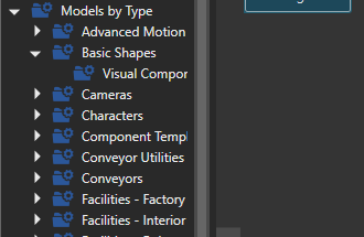
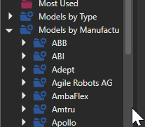
Classify Models by Type from eCatalog.
Add Welding Torch welding tools from Robot Tools.

Add Cylinder
This time we will add Cylinder.
Add Visual Components>Basic Shapes>Cylinder Geo and adjust the size.

Add Program-1
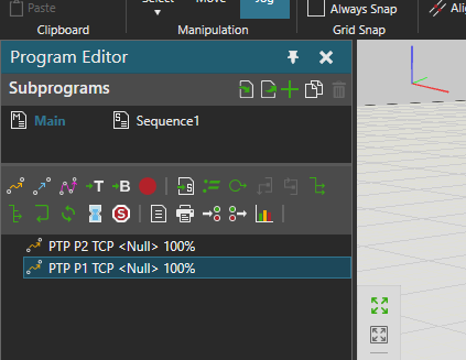
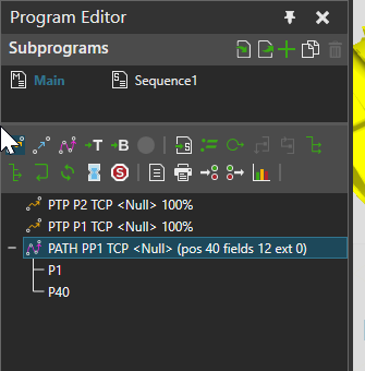
The next step is to add the robot program. The figure below shows only PTP P2 and PTP P1.
- PTP P2 is the standby position before work
- PTP P1 is the standby position
Add Path Statement
Create a Path Motion for the robot to move along the Cylinder Geo.
Click on “Path Statement” to add a Path Statement to your program.

Done!But that is still not enough, so we need to specify a Path move Point.

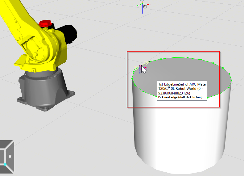
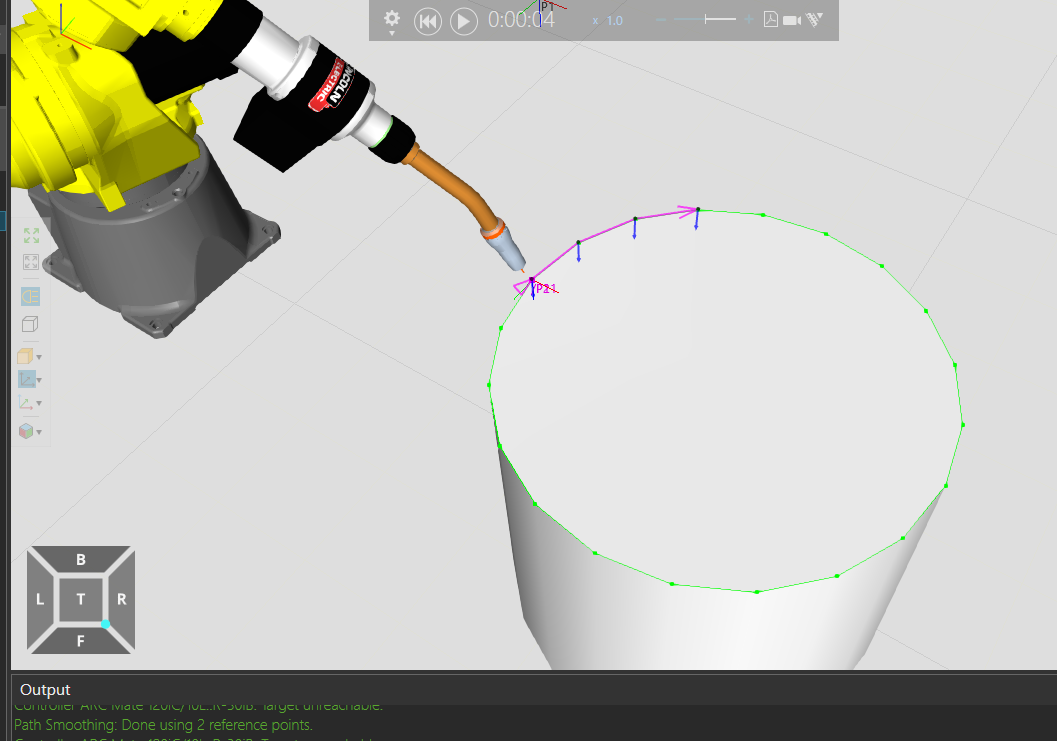
Can you see some dots are on the edge of Cylinder Geo now?

You can specify a move point in the Path by clicking on that point with the Mouse.
Next, do you see the Pink colored arrow? This means that Point1 and Point2 will go in the direction of the arrow (clockwise in the figure below).
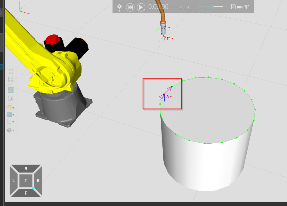
Let’s specify the direction and Point to be specified in this way.
In Visual Components, specifying a point in a Path can be completed by simply Mouse Clicking!

Okay, we are now around the edge of Cylinder Geo.

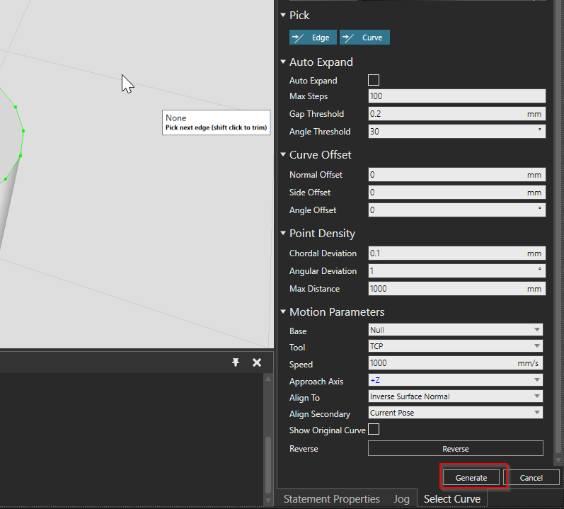
In fact, Visual Components can allow you to configure the number of Points, angles, speeds, and spacing to be finely tuned depending on the application.

If the parameters are OK, generate the Path with the Generate button.
Done!
Arrange the Program
Move the generated PATH Statement between PTP P2 and PTP P1.
In other words, it is a wait>path move>wait movement.

There are no complicated operations, and commands can be moved simply by Drag and Drop with the Mouse.
Test it!
Let’s test it once!

Bonus:Configuration
Let’s talk a little more about setting up Visual Components. When you were creating your robot program, you may have seen strange movements like the one in the GIF below. It is an unnecessary posture change of the robot.
The cause is that the robot has only one TCP, but the posture can be the same TCP with multiple postures. And in the posture you can also set each Statement, if Statement1 and Statement2 are set differently, it could lead to useless movement.
Click on PTP P2.

On the right, you will see a configuration screen called Statement Properties, and in Configuration you have now set NDB.
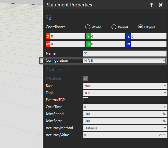
Just by changing Configuration, the posture of the robot is 100% different, but only the TCP is the same Point.

Add Halt
Let’s Add a Halt instruction; the Halt Statement can be used to pause the robot’s Simulation.

Now let’s add a Statement after the Path Statement.

Test it!
As shown in the figure below, simulation is paused when the robot’s Path Statement is completed, and resumed when the Play Button is clicked.

Add Delay
Next is the Delay Statement, which simply creates a delay between Statements.
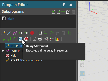
Put Delay Statement next to PTP P2 Statement and double click.
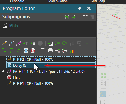
Delay time can be set from the Statement Properties screen.
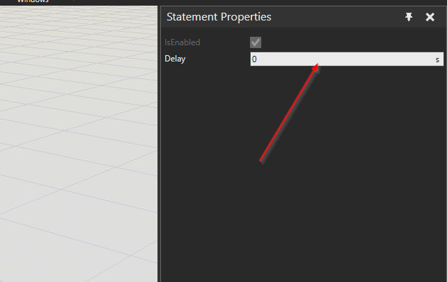
For now, let us set it to 1s.

Test it!
It may be a little confusing, but the robot now executes the Path Statement after a 1s delay.
Disable Statement
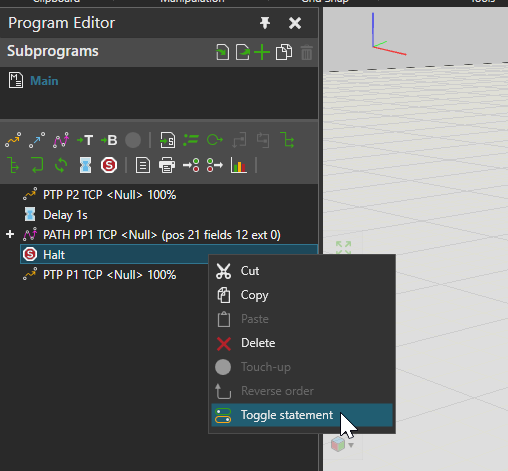
Visual Components also has the ability to disable Statements. Right click on the Statement you wish to disable>Toggle Statement.
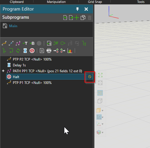
A small inhibit ICON is next to the Statement, indicating that the Halt Statement has now been invalidated. This means that the Halt Statement has now been disabled.
Test it!
Done!Halt Statement has been Skipped.

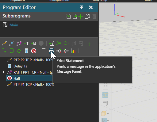
Print Message
The last one is Print Statement, which allows you to output text to the Visual Components Terminal.
Add a Print Statement before the Halt Statement and double-click to test.

The Statement Properties screen appears on the right, allowing you to set the Message you wish to Print.

Once the character to be Printed is set, the character to be displayed will also be visible in the Statement.

Test it
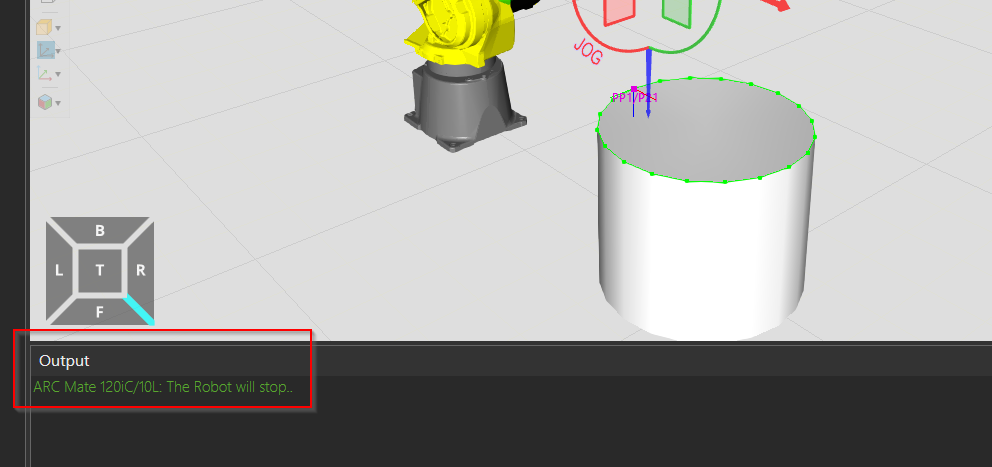
After running Simulation, Message was displayed in Output!

The text here will be the text you have just set!