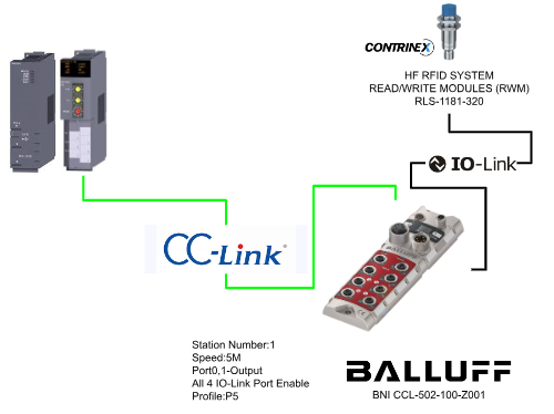
In this article, we will build an IO-LINK Master by communicating with Mitsubishi Q CPU’s CC-LINK module QJ61BT11 and BALLUFF’s CC-LINK Slave IO-LINK Master BNI CCL-502-100-Z001.
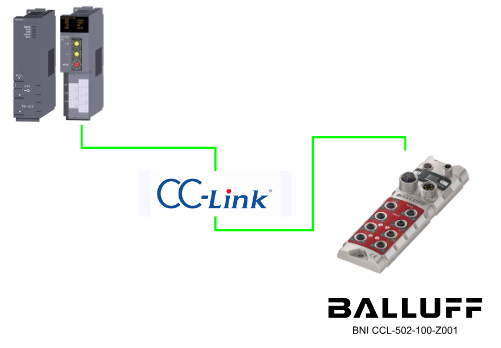
In BNI CCL-502-100-Z001 each letter actually has its own meaning.
- BNI=Balluff network interface
- CCL=CC-CLink interface
- 502=Function Block,IP 67+IO-Link, max. 16 IN/OUT, 4 IO-LINK connections
- Z001=Version
Thanks!
This article is for the loan of BNI CCL-502-100-Z001 from Balluff Japan. Thank you for your cooperation!

Video
Japanese Version
English Version
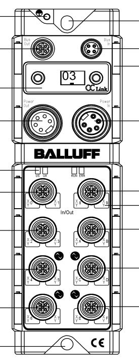
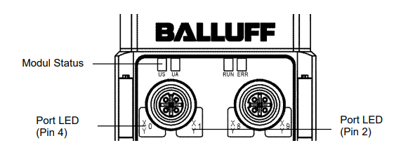
LED Status
Balluff’s BNI CCL-502-100-Z001 has US/UA for Module Status indication, RUN/ERR LEDs for module status, and LEDs for each port status.
US
| Green | Power supply OK |
| Red | Power supply <18v |
| OFF | No power supply |
UA
| Green | Power supply OK |
| Red | Power supply <18v |
| OFF | No power supply |
Run
| Green | Communication with CC-Link Master OK |
| OFF | Timeout and CC-Link communication problems. |
Error
| Red ON | communication error |
| Red Flash | CC-LINK Version problem, module configuration changed. |
| OFF | normalcy |
LED- SIO Input Mode Pin4/Pin2
| OFF | Input signal = 0 |
| Yellow | Input signal = 1 |
| Red | PIN1/3短絡 |
LED- SIO OutputMode Pin4/Pin2
| OFF | Output signal = 0 |
| Yellow | Output signal = 1 |
| Red | PIN1/3 Short Circuit |
LED- SIO IO-LINK Mode Pin4
| OFF | IO-LINK is not set to Enable. |
| Green ON | IO-LINK is enabled and still communicating. |
| Green Flash | IO-LINK enabled, but not communicating. |
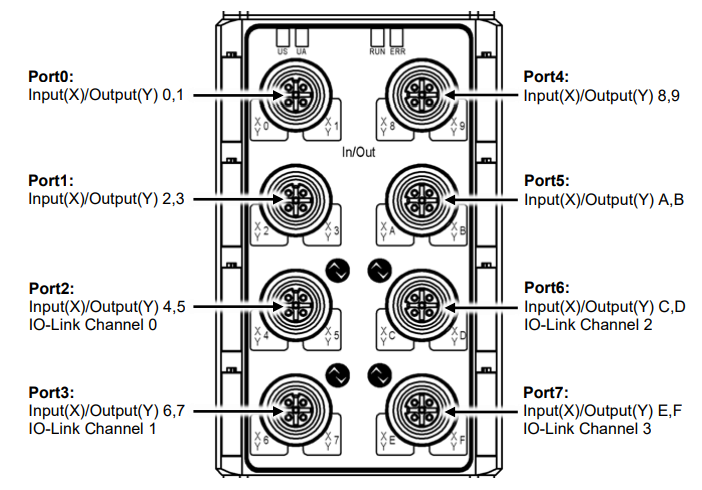
Ports
Ports are counted from top to bottom, left to right, Port0,1,4,5. are normal input/output, Port2,3,6,7 are input/output, and even IO Channel can be set.
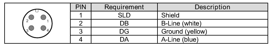
CC-LINK BUS In
The following is a pin diagram of the CC-Link Bus input, M12, A-coded, male.
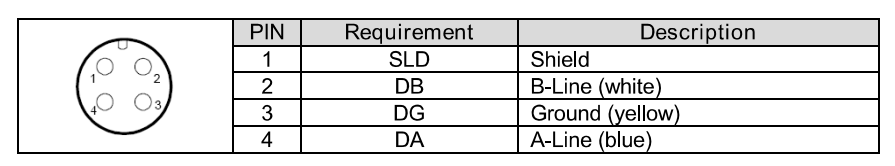
CC-LINK Bus Out
The following is a pin diagram of the CC-Link Bus outputs: M12, A-coded, female.
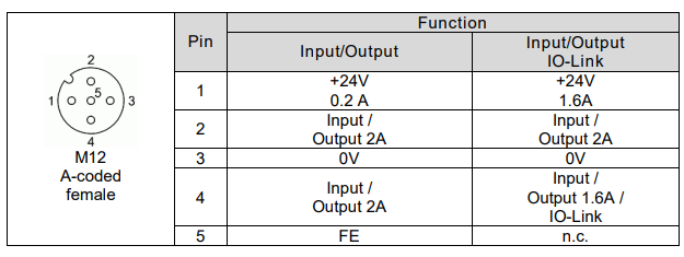
Connecting sensor/Actuators
The following is an input/output pin diagram, M12, A-coded, female.
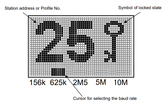
Display
BNI CCL-502-100-Z0001 has a display on the module to check and change the current module status and settings. CC-Link Profile P1 (3 stations occupied).
Communication
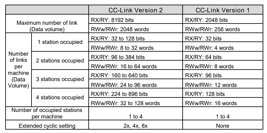
BNI CCL-502-100-Z01 also supports both CC-Link Ver1 and Ver2.
Overview
Profile
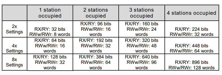
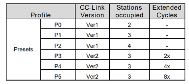
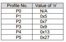
BNI CCL-502-100-Z001 is available in five different Profiles, and the CCLINK Version, number of occupied stations, and expansion cycle will change depending on the Profile selected.
Default setting is 3 for station number, 10 Mbps for communication speed, and P1 for CC-CLINK Profile.
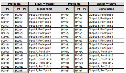
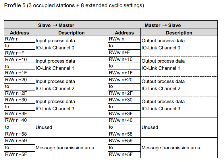
Mappings
The Profile used for this project is P5.
Rxm0-F/Rym0-F
For example, if it starts with 500, it will be X500-X50F and Y500-Y50F.
Rxm+1 0-F/Rym+1 0-F
For example, if you start with 500, you will end up with X510-X10F and Y510-Y51F.
Rxm+2 0-F/Rym+2 0-F
For example, if you start with 500, you will end up with X520-X52F and Y520-Y52F.
Rxm+3 0-F/Rym+3 0-F
For example, if you start with 500, you will end up with X530-X54F and Y530-Y54F.
Rx(m+n) 0-F/R(ym+n) 0-F
For example, if you start with 500, you will end up with X770-X77F and Y770-Y77F.
This time we set P5, so we start with X500 and 50+27=77 to get X770.
RWr RWw
We have set P5, so the Remote input Register is thought of as W500 to W50F.
Implementation
Balluff Side
Communication speed is 5M, Profile=P5, Port0,1 are output, and 4 ports are also IO-LINK ports.
GXWORKS Side
Let’s start with the Mitsubishi side.
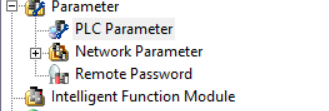
Hardware Configuration
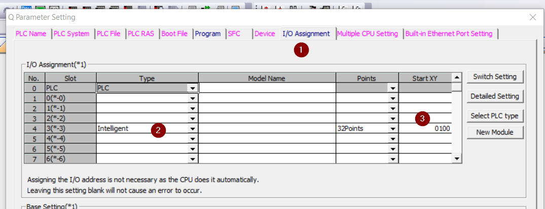
Put the CC-Link module into Hardware Configuration. Click Parameter>PLC Parameter.
Open the I/O Assignment tab and select “Integent” as the Type for the slot in which the CC-LINK module is inserted>Points is 32 Points and StartXY is 0100. The StartXY will be used for the next CCLINK construction.
CC-Link Configuration
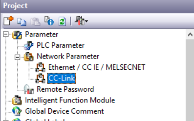
Open Parameter>Network Parameter>CC-CLINK.
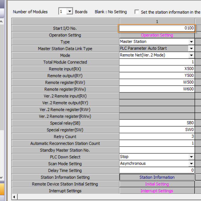
The Start I/O No. is the same as the number set in the previous Step of Hardware Configuration. Therefore, 0100 is used this time. Set other RX, RY, etc. according to the application.
Balluff Station setup
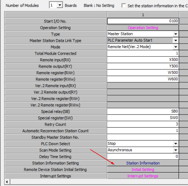
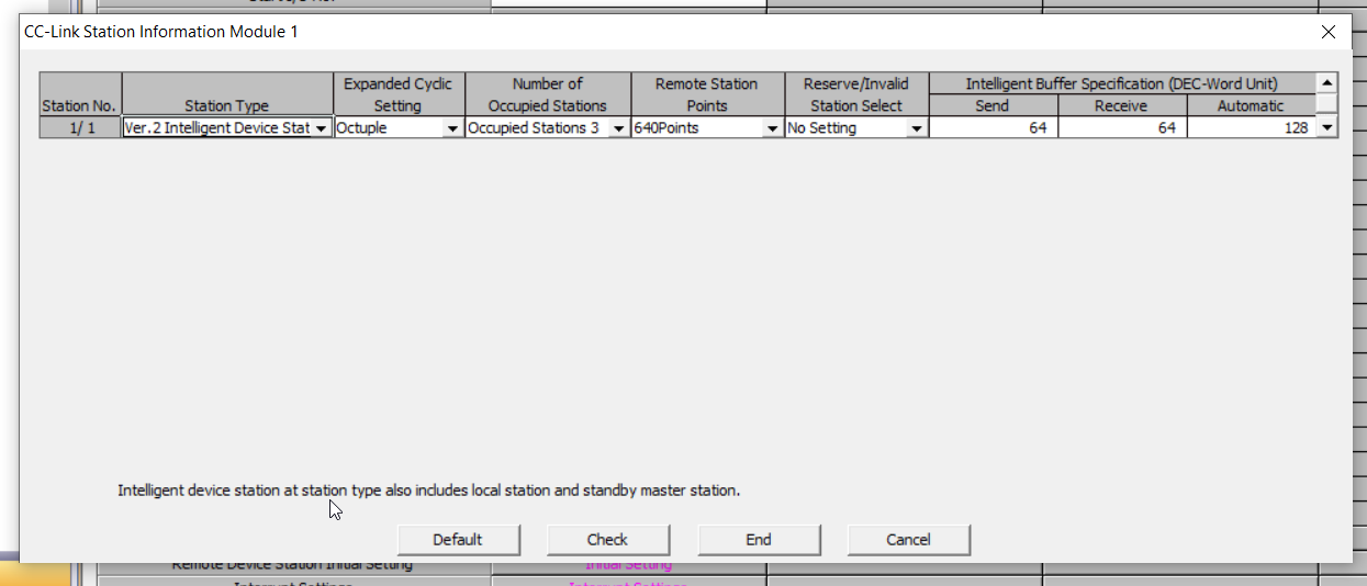
Set Balluff’s CC-LINK IO Link Master to CC-LINK Network. Click on Station Information under Station Information Settings.
This time, set Balluff to Profile P5.
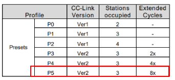
Since P5 is Ver2, Station should be Station Type, and Stations occupied and Extended Cycles should also match P5.
Programming
The next step is to create a program. I use not only Ladder but also structure, Function, and ST. You can use the structures and Function Blocks you created in this Sample as they are.
Structured Data Types
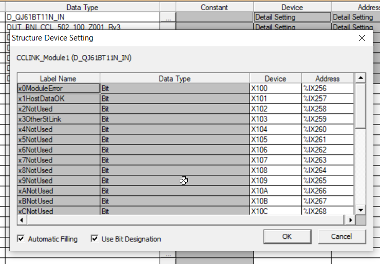
D_QJ61BT11N_IN
This is the signal when received with the same structure as the previous Wago CC-LINK Coupler.
| x0ModuleError Bit x1HostDataOK Bit x2NotUsed Bit x3OtherStLink Bit x4NotUsed Bit x5NotUsed Bit x6NotUsed Bit x7NotUsed Bit x8NotUsed Bit x9NotUsed Bit xANotUsed Bit xBNotUsed Bit xCNotUsed Bit xDNotUsed Bit xENotUsed Bit xFReady Bit x10NotUsed Bit x11NotUsed Bit x12NotUsed Bit x13NotUsed Bit x14NotUsed Bit x15NotUsed Bit x16NotUsed Bit x17NotUsed Bit x18NotUsed Bit x19NotUsed Bit x1ANotUsed Bit x1BNotUsed Bit x1CNotUsed Bit x1DNotUsed Bit x1ENotUsed Bit x1FNotUsed Bit |
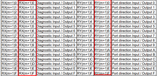
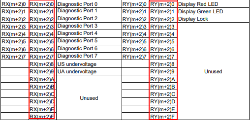
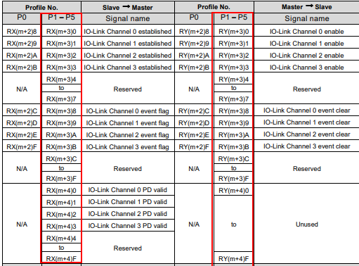
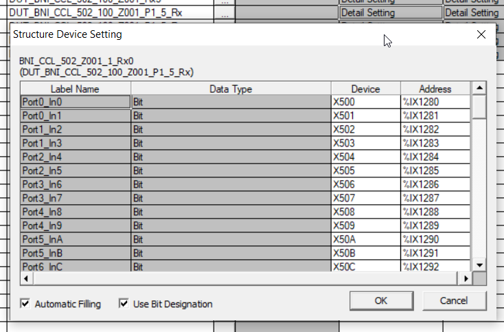
DUT_BNI_CCL_502_100_Z001_P1_5_Rx
This is where you define the Balluff devices according to the Mapping in the Manual, and you can use Profiles P1 to P5. IOLINK_Chx_Established is for IO-LINK communication Ok and IOLINK_Chx_DataValid is for its data validity.
| Port0_In0 Bit Port0_In1 Bit Port1_In2 Bit Port1_In3 Bit Port2_In4 Bit Port2_In5 Bit Port3_In6 Bit Port3_In7 Bit Port4_In8 Bit Port4_In9 Bit Port5_InA Bit Port5_InB Bit Port6_InC Bit Port6_InD Bit Port7_InE Bit Port7_InF Bit Port0_InOut0_Diagnostic Bit Port0_InOut1_Diagnostic Bit Port1_InOut2_Diagnostic Bit Port1_InOut3_Diagnostic Bit Port2_InOut4_Diagnostic Bit Port2_InOut5_Diagnostic Bit Port3_InOut6_Diagnostic Bit Port3_InOut7_Diagnostic Bit Port4_InOut8_Diagnostic Bit Port4_InOut9_Diagnostic Bit Port5_InOutA_Diagnostic Bit Port5_InOutB_Diagnostic Bit Port6_InOutC_Diagnostic Bit Port6_InOutD_Diagnostic Bit Port7_InOutE_Diagnostic Bit Port7_InOutF_Diagnostic Bit Port0_Diagnostic Bit Port1_Diagnostic Bit Port2_Diagnostic Bit Port3_Diagnostic Bit Port4_Diagnostic Bit Port5_Diagnostic Bit Port6_Diagnostic Bit Port7_Diagnostic Bit Us_UnderVoltage Bit Ua_UnderVlotage Bit bRx_x2A Bit bRx_x2B Bit bRx_x2C Bit bRx_x2D Bit bRx_x2E Bit bRx_x2F Bit IOLINK_Ch0_Established Bit IOLINK_Ch1_Established Bit IOLINK_Ch2_Established Bit IOLINK_Ch3_Established Bit bRx_x34 Bit bRx_x35 Bit bRx_x36 Bit bRx_x37 Bit IOLINK_Ch0_EventFlag Bit IOLINK_Ch1_EventFlag Bit IOLINK_Ch2_EventFlag Bit IOLINK_Ch3_EventFlag Bit bRx_x3C Bit bRx_x3D Bit bRx_x3E Bit bRx_x3F Bit IOLINK_Ch0_DataValid Bit IOLINK_Ch1_DataValid Bit IOLINK_Ch2_DataValid Bit IOLINK_Ch3_DataValid Bit bRx_x44 Bit bRx_x45 Bit bRx_x46 Bit bRx_x47 Bit bRx_x48 Bit bRx_x49 Bit bRx_x4A Bit bRx_x4B Bit bRx_x4C Bit bRx_x4D Bit bRx_x4E Bit bRx_x4F Bit |
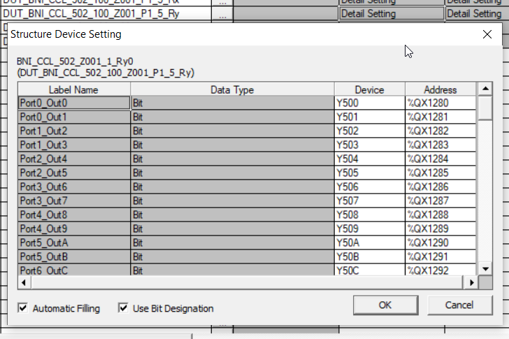
DUT_BNI_CCL_502_100_Z001_P1_5_Ry
This is where you define the Balluff devices according to the Mapping in the Manual, P1 to P5 profiles are available, the most commonly used are IOLINK_Chx_Enable and Portx_IsOutput, where x=Port number. Enable indicates whether the corresponding Port should be used as an IO-LINK Port (True=IO-LINK Port), and Portx_IsOutput indicates whether the corresponding Port should be used as an output (True=Output).
| Port0_Out0 Bit Port0_Out1 Bit Port1_Out2 Bit Port1_Out3 Bit Port2_Out4 Bit Port2_Out5 Bit Port3_Out6 Bit Port3_Out7 Bit Port4_Out8 Bit Port4_Out9 Bit Port5_OutA Bit Port5_OutB Bit Port6_OutC Bit Port6_OutD Bit Port7_OutE Bit Port7_OutF Bit Port0_IsOutput Bit Port1_IsOutput Bit Port2_IsOutput Bit Port3_IsOutput Bit Port4_IsOutput Bit Port5_IsOutput Bit Port6_IsOutput Bit Port7_IsOutput Bit Port8_IsOutput Bit Port9_IsOutput Bit PortA_IsOutput Bit PortB_IsOutput Bit PortC_IsOutput Bit PortD_IsOutput Bit PortE_IsOutput Bit PortF_IsOutput Bit Display_LED_Red Bit Display_LED_Green Bit Display_LOCK Bit bRY_x23 Bit bRY_x24 Bit bRY_x25 Bit bRY_x26 Bit bRY_x27 Bit bRY_x28 Bit bRY_x29 Bit bRY_x2A Bit bRY_x2B Bit bRY_x2C Bit bRY_x2D Bit bRY_x2E Bit bRY_x2F Bit IOLINK_Ch0_Enable Bit IOLINK_Ch1_Enable Bit IOLINK_Ch2_Enable Bit IOLINK_Ch3_Enable Bit bRY_x34 Bit bRY_x35 Bit bRY_x36 Bit bRY_x37 Bit IOLINK_Ch0_EventClear Bit IOLINK_Ch1_EventClear Bit IOLINK_Ch2_EventClear Bit IOLINK_Ch3_EventClear Bit bRY_x3C Bit bRY_x3D Bit bRY_x3E Bit bRY_x3F Bit bRY_x40 Bit bRY_x41 Bit bRY_x42 Bit bRY_x43 Bit bRY_x44 Bit bRY_x45 Bit bRY_x46 Bit bRY_x47 Bit bRY_x48 Bit bRY_x49 Bit bRY_x4A Bit bRY_x4B Bit bRY_x4C Bit bRY_x4D Bit bRY_x4E Bit bRY_x4F Bit |
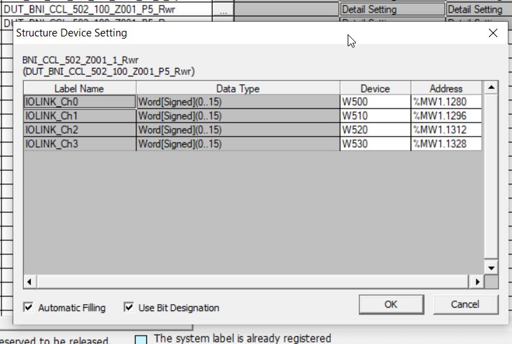
DUT_BNI_CCL_502_100_Z001_P5_Rwr
This one defines Balluff’s devices according to the Mapping in Manual, with the Profile setting in P5, each IO-Link Port receives 16Words of data from an IO-Link device.
| IOLINK_Ch0 Word[Signed](0..15) IOLINK_Ch1 Word[Signed](0..15) IOLINK_Ch2 Word[Signed](0..15) IOLINK_Ch3 Word[Signed](0..15) |
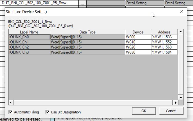
DUT_BNI_CCL_502_100_Z001_P5_Rww
This one defines Balluff’s devices according to the Mapping in Manual, with the Profile setting in P5, each IO-Link Port sends 16Words of data from the IO-Link device.
| IOLINK_Ch0 Word[Signed](0..15) IOLINK_Ch1 Word[Signed](0..15) IOLINK_Ch2 Word[Signed](0..15) IOLINK_Ch3 Word[Signed](0..15) |
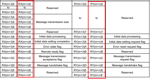
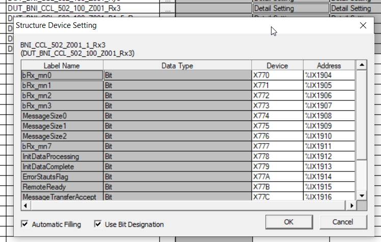
DUT_BNI_CCL_502_100_Z001_Rx3
This one defines Balluff devices according to the Mapping in Manual, with Profile settings from P1 to P5, and Handshake input from the module. The ones that could be used are.
- InitDataProcessing、Initialization request from module
- InitDataComplete、Initialization from module completed
- ErrorStautsFlag、Error condition from module
- RemoteReady、Ready state from module
| bRx_mn0 Bit bRx_mn1 Bit bRx_mn2 Bit bRx_mn3 Bit MessageSize0 Bit MessageSize1 Bit MessageSize2 Bit bRx_mn7 Bit InitDataProcessing Bit InitDataComplete Bit ErrorStautsFlag Bit RemoteReady Bit MessageTransferAccept Bit MessageTransferHandShake Bit bRx_mnE Bit bRx_mnF Bit |
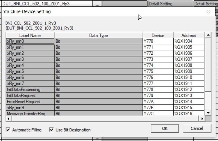
DUT_BNI_CCL_502_100_Z001_Ry3
This one defines Balluff’s devices according to Manual’s Mapping, with Profile settings from P1 to P5, and Handshake output to the module. You could use:
- InitDataProcessing、During initialization process sent to module
- InitDataComplete、Completed initialization sent to module
- ErrorResetRequest、Error reset sent to module
| bRy_mn0 Bit bRy_mn1 Bit bRy_mn2 Bit bRy_mn3 Bit bRy_mn4 Bit bRy_mn5 Bit bRy_mn6 Bit bRy_mn7 Bit InitDataProcessing Bit InitDataRequest Bit ErrorResetRequest Bit bRy_mnB Bit MessageTransferReq Bit MessageTransferHandShake Bit bRy_mnE Bit bRy_mnF Bit |
FB/FUN
FB_BNI_CCL_502_Z001_HandShake
Local Label
Rx3 and Ry3 are the module and the Handshake area (the structure defined earlier). bCCLinkMasterStatus is the status of the CC-LINK Master, since there is no point in sending data if the CC-LINK Master is in error.
| VAR_INPUT Rx3 DUT_BNI_CCL_502_100_Z001_Rx3 VAR_INPUT bInitIO Bit VAR_INPUT bCCLinkMasterStatus Bit VAR_INPUT bConfig Bit VAR_OUTPUT Ry3 DUT_BNI_CCL_502_100_Z001_Ry3 VAR_OUTPUT bRemoteOK Bit VAR iStep Word[Signed] |
Program
Although not mentioned in Balluff’s Manual, the module actually requires such an initialization program. When an initialization request comes in from a module, it simply returns the Flag of the request from the PLC.
| (*Auto Reset*) Ry3.ErrorResetRequest:=Rx3.ErrorStautsFlag AND bCCLinkMasterStatus; (*Data Initing..*) Ry3.InitDataProcessing:=Rx3.InitDataProcessing AND bCCLinkMasterStatus AND bConfig; (*Remote OK*) bRemoteOK:=Rx3.RemoteReady; |
FB_CONTRINEX
This is the CONTRINEX IO Link Sensor we always use. For the actual program and configuration, please refer to Reference Link, where the article begins.
Local Label
| VAR_INPUT IOLINKData Word[Signed](0..15) VAR_OUTPUT HaveTags Bit VAR_OUTPUT RFField Bit VAR_OUTPUT NBTags Word[Unsigned]/Bit String[16-bit] VAR_OUTPUT UID0 Word[Unsigned]/Bit String[16-bit] VAR_OUTPUT UID1 Word[Unsigned]/Bit String[16-bit] VAR_OUTPUT UID2 Word[Unsigned]/Bit String[16-bit] VAR_OUTPUT UID3 Word[Unsigned]/Bit String[16-bit] VAR_OUTPUT UID4 Word[Unsigned]/Bit String[16-bit] VAR_OUTPUT UID5 Word[Unsigned]/Bit String[16-bit] VAR_OUTPUT UID6 Word[Unsigned]/Bit String[16-bit] VAR_OUTPUT UID7 Word[Unsigned]/Bit String[16-bit] |
Program
Create according to CONTRINEX Mapping.
| D0:=IOLINKData[0]; RFField:= (D0&2#0001_0000_0000_0000) <> 0 ; HaveTags:= (D0&2#0010_0000_0000_0000) <> 0 ; NBTags:= SHR((D0&2#0000_1111_0000_0000),8); UID0:=D0&2#0000_0000_1111_1111; D0:=IOLINKData[1]; UID1:=SHR((D0&2#1111_1111_0000_0000),8); UID2:=SHR((D0&2#0000_0000_1111_1111),8); D0:=IOLINKData[2]; UID3:=SHR((D0&2#1111_1111_0000_0000),8); UID4:=SHR((D0&2#0000_0000_1111_1111),8); D0:=IOLINKData[3]; UID5:=SHR((D0&2#1111_1111_0000_0000),8); UID6:=SHR((D0&2#0000_0000_1111_1111),8); D0:=IOLINKData[4]; UID5:=SHR((D0&2#1111_1111_0000_0000),8); |
;
Global Label
Next, define IO Data in Global Label.
| VAR_GLOBAL CCLINK_Module1 D_QJ61BT11N_IN VAR_GLOBAL BNI_CCL_502_Z001_1_Ry3 DUT_BNI_CCL_502_100_Z001_Ry3 VAR_GLOBAL BNI_CCL_502_Z001_1_Rx3 DUT_BNI_CCL_502_100_Z001_Rx3 VAR_GLOBAL BNI_CCL_502_Z001_1_Rx0 DUT_BNI_CCL_502_100_Z001_P1_5_Rx VAR_GLOBAL BNI_CCL_502_Z001_1_Ry0 DUT_BNI_CCL_502_100_Z001_P1_5_Ry VAR_GLOBAL BNI_CCL_502_Z001_1_Rwr DUT_BNI_CCL_502_100_Z001_P5_Rwr VAR_GLOBAL BNI_CCL_502_Z001_1_Rww DUT_BNI_CCL_502_100_Z001_P5_Rww |
CCLINK_Module1
From the beginning, StartXY was set from 0100, so set X100.
BNI_CCL_502_Z001_1_Ry3
The Manual has the M+n calculation method on it, and I set the CC-LINK Network Tab to Remote output from Y500, so the module’s Handshake Data starts from 500+270=Y770.
BNI_CCL_502_Z001_1_Rx3
The Manual has the M+n calculation method on it, and I set the CC-LINK Network Tab to Remote output from X500, so the module’s Handshake Data starts at 500+270=X770.
BNI_CCL_502_Z001_1_Rx0
The CC-LINK Network Tab is set to Remote input from X500, so the module input data starts from X500.
BNI_CCL_502_Z001_1_Ry0
Since the CC-LINK Network Tab was set to Remote input from Y500, the module input data starts from Y500.
BNI_CCL_502_Z001_1_Rwr
The CC-LINK Network Tab was set to Remote Regisiter input from W500, so the module input data starts from W500.
BNI_CCL_502_Z001_1_Rwy
The CC-LINK Network Tab was set to Remote Regisiter input from W600, so the module input data starts from W600.
Scan
It’s a long story, but the last one is the Scan program for Main.
Local Label
Define Instance of IO-LINK Device Function Block for Handshkre and CONTRINEX.
| VAR HandShake FB_BNI_CCL_502_Z001_HandShake VAR bConfig Bit VAR RWM1 FB_CONTRINEX |
Program
At first, configure each Port: Por0,1 should be output and the four IO-LINK ports should also be enabled.
| IF NOT bConfig THEN BNI_CCL_502_Z001_1_Ry0.Port0_IsOutput:=TRUE; BNI_CCL_502_Z001_1_Ry0.Port1_IsOutput:=TRUE; BNI_CCL_502_Z001_1_Ry0.IOLINK_Ch0_Enable:=TRUE; BNI_CCL_502_Z001_1_Ry0.IOLINK_Ch1_Enable:=TRUE; BNI_CCL_502_Z001_1_Ry0.IOLINK_Ch2_Enable:=TRUE; BNI_CCL_502_Z001_1_Ry0.IOLINK_Ch3_Enable:=TRUE; bConfig:=TRUE; END_IF; RWM1( IOLINKData:=BNI_CCL_502_Z001_1_Rwr.IOLINK_Ch2 ,HaveTags:=M0 ,NBTags:=D10 ,UID0:=D11 ,UID1:=D12 ,UID2:=D13 ,UID3:=D14 ,UID4:=D15 ,UID5:=D16 ,UID6:=D17 ,UID7:=D18 ); HandShake( Rx3:=BNI_CCL_502_Z001_1_Rx3 ,bConfig:=bConfig ,bCCLinkMasterStatus:=CCLINK_Module1.xFReady ,Ry3:=BNI_CCL_502_Z001_1_Ry3 ); |
Result
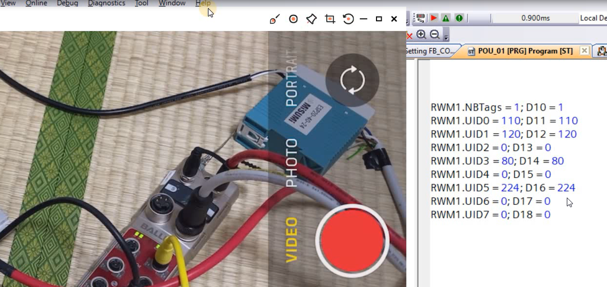
Reading a single RFID from the CONTRINEX Reader will reflect NBTags=1 and also the UID.
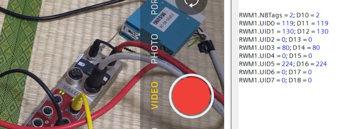
Reading two RFIDs from the CONTRINEX Reader results in NBTags=2.
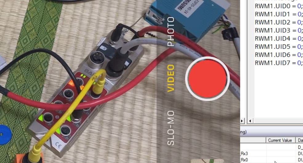
Finally, when outputs Y500 and Y501 were set to True, the LEDs on the module also lit up.
Download the Project
Download the GXWORKS2 project from the Link below.
https://github.com/soup01Threes/GXWROKS/blob/main/BIN_CLL_502_100_Z001_Demo.gxw