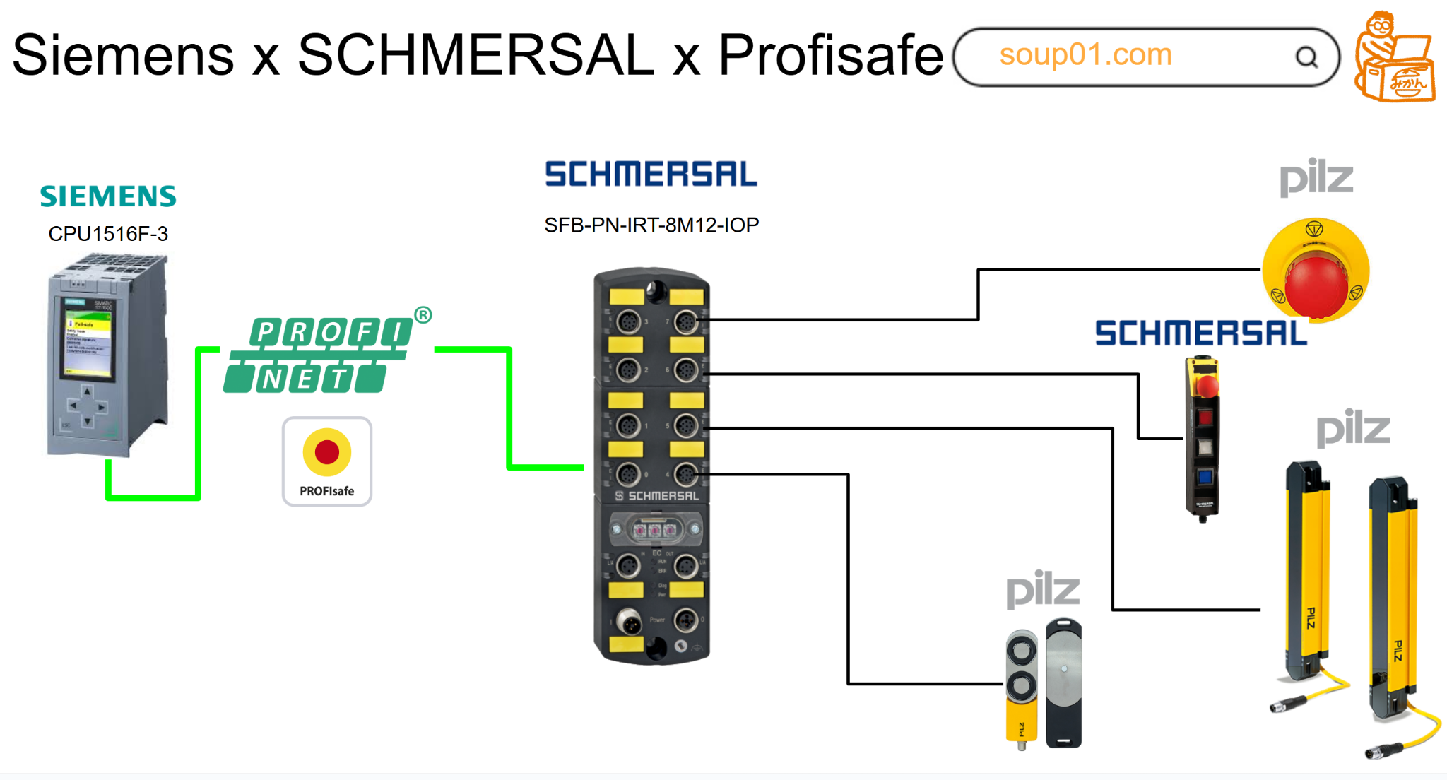
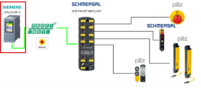
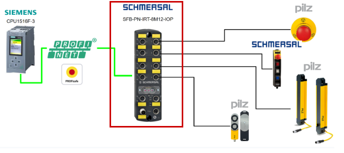
In this article, we will build a Profinet/Profisafe network with a Siemens CPU1516F-36 and connect it to a Schmersal SFB-PN-IRT-8M12-IOP-V2. Safety devices used include Pilz emergency stops and light curtains, door locks, and the Schmersal BDF200-FB-NHK-LT-LT-LT-2875 door lock.
Now, let’s enjoy FA.
Reference Video
Siemens.Schmersal SFB-PN-IRT-8M12-IOPとProfisafeで接続しましょう
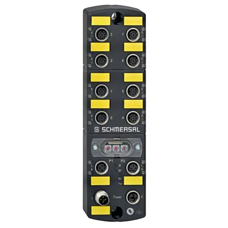
SFB-PN-IRT-8M12-IOP-V2?
The SFB-PN-IRT-8M12-IOP-V2 safety field box is designed to allow connection of up to 8 safety switchgear units via parallel IO signals to a PROFINET/PROFIsafe network. Additionally, up to 4 BDF200-FB control panels can be connected to device ports X4 to X7.
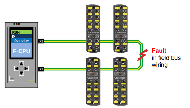
In large-scale safety applications, multiple field boxes can be connected in series to the power supply and fieldbus.
Please note that the user must evaluate and design the safety chain in accordance with relevant standards and required safety levels. Non-safety IO signals from connected devices are connected to the control system via the fieldbus.
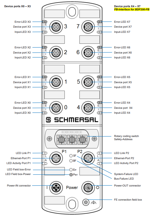
Layout
This is the Layout for the SFB-PN-IRT-8M12-IOP-V2.
Safety Inputs
Safety Inputs and Test Pulse Outputs: The SFB-PN-IRT-8M12-IOP-V2 features 2 safety inputs and 2 test pulse outputs for supplying dry contacts at each of the 8 device ports X0 to X7.
These safety inputs can be used for the following applications:
-
1-channel safety switch (1oo1) with dry NC contacts
- Cross-fault monitoring to all other safety inputs of the field box
- Configurable debounce filter / stabilization time filter for input signals
- Supply contacts via test pulse outputs with 1ms test pulse duration and 500ms test pulse interval
-
2 channel safety switches (1oo2) with dry NC contacts
- Cross-fault monitoring to all other safety inputs of the field box
- Configurable debounce filter / stabilization time filter for input signals
- Contact supply via test pulse outputs with 1ms test pulse duration and 500ms test pulse interval
-
2 channel Safety switches (1oo2) with 24 V-PNP solid state outputs (OSSDs)
- No cross-fault monitoring of device connection cables by the field box
- Configurable debounce filter / stabilization time filter for input signals
- Supplying 24V DC without test pulses to the safety inputs of the safety switchgear – when the OSSD is switched on, negative test pulses of 10μs to 1ms length and 20ms to 120s interval must be transmitted.
Safety outputs
Safety Output: The SFB-PN-IRT-8M12-IOP-V2 features a safety digital output at each of the 8 device ports X0 to X7 for controlling loads up to 0.8A, and configurable safety signal outputs for controlling 2-channel safety inputs up to 15mA.

These safety outputs can be used for the following applications:
-
Safety output via 1 wire (Digital Output DO)
- Safety digital output up to PL d (PP switching) for controlling interlock solenoids, etc.
- Test output with short-circuit and overload protection
-
2-wire safety output (Digital Output DO and Test Pulse Output Y1)
- Safety digital output up to PL e (2P switching) for 2-channel control of interlocks with 2-channel locking functions or SRB-E-301ST safety relay modules, etc.
- Test output with short-circuit and overload protection
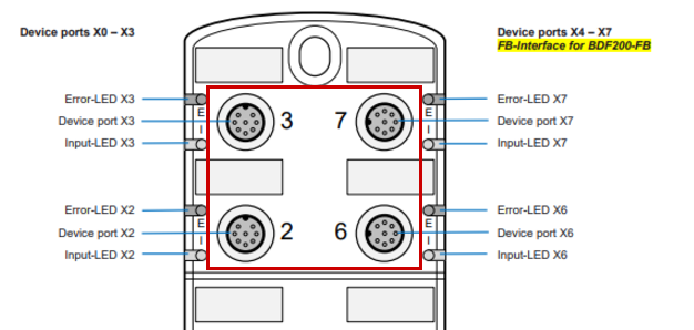
Diagnostic input / FB interface
The SFB-PN-IRT-8M12-IOP-V2 features one diagnostic input at each of the 8 device ports X0 to X7 for status signals from connected safety switchgear. At the 4 device ports X4 – X7, the FB interface is integrated into this input. Non-safety signals from command and signaling devices such as the BDF200-FB are transmitted via the single-wire FB interface. The FB interface automatically detects whether safety switchgear with an integrated FB interface is connected.
Cross fault monitoring
The default setting is used for safety switchgear with electronic OSSDs. When using safety switchgear with dry contacts, Cross fault monitoring must be enabled.
For safety switchgear with electronic OSSDs, cross-fault detection of the device connection cable must be performed by the safety switchgear.
The SFB-PN-V2 monitors the test pulses on the outputs of the safety switchgear.
PROFINET
Since the SFB-PN-IRT-8M12-IOP-V2 used in this article is a Field IO Box that supports PROFINET/PROFISAFE, I will briefly introduce PROFINET here.

PROFINET IO Communications..
PROFINET IO is an open communication protocol in accordance with IEC 61784-2. The communication protocol is based on Ethernet. Data is exchanged between a control unit called a PROFINET IO controller and connected users called PROFINET IO devices.
PROFINET IO communication is based on a full-duplex Ethernet network operating at 100 Mbit/s, where IO controllers and IO devices communicate using Ethernet telegrams.
Devices exchange data periodically based on the provider and consumer principle. A device acts as a receiver (consumer) and transmitter (provider) simultaneously.
The IO controller sends output data to the IO device and receives input data from the IO device. In turn, the IO device sends input data and receives output data. Other components of the communication protocol include telegrams for acyclic communication for parameter transfer, as well as the ability to read/write access to I&M data or manufacturer-specific functions.

PROFIsafe communication
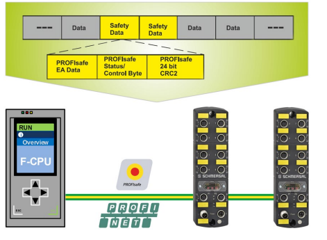
PROFIsafe is a functional safety extension of standard communication via PROFINET or PROFIBUS. Communication based on PROFIsafe incorporates various detection mechanisms against alterations, transmission errors, changes in telegram sequence, etc. The SFB-PN Safety Field Box is a PROFIsafe module that complies with “PROFIsafe – Profile for Safety Technology on PROFIBUS DP and PROFINET IO”. This module can establish secure communication with a PROFIsafe master.

SFB-PN in the PROFINET System..
The SFB-PN safety module is both a PROFINET IO device and a PROFIsafe slave. It sends and receives data to/from the F-PLC via PROFIsafe telegrams. PROFIsafe telegrams are transferred within standard PROFINET telegrams. (Black Channel principle)
It processes safe input data and periodically sends safe output data to the PROFIsafe slave. PROFIsafe telegrams contain control bits and status bits. The telegram informs the state of the master/slave and initiates state changes if necessary.
The SFB-PN safety module detects errors within the module, as well as errors in installed or connected safety switchgear. If an error is detected in the safety section, the module returns to a safe state.
SFB-PN セーフティモジュールは、モジュール内のエラー、設置または接続されたセーフティスイッチ装置のエラーを検出します。 セーフティセクションでエラーが検出されると、モジュールは安全状態に戻ります。
Media redundancy protocol (MRP)
The MRP protocol according to IEC 62439 describes PROFINET redundancy, and the reconfiguration time of the communication path using TCP/IP and RT frames is less than 200 ms after a failure. Error-free operation of the automation system requires a Media Redundancy Manager (MRM) and multiple Media Redundancy Clients (MRC) arranged in a ring.
The function of the Media Redundancy Manager (MRM) is to check if the ring structure required by the configuration is operational.
This is done by sending periodic test telegrams. As long as the test telegram is received again by the MRM, the ring structure is intact. The MRM uses this behavior to prevent telegram circulation and convert the ring structure into a line structure.
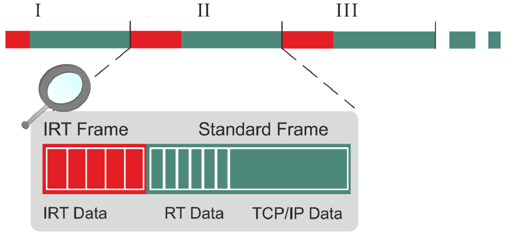
PROFINET IRT
In PROFINET, the IRT concept (isochronous real time) defines clock-synchronized data exchange by transmitting data packages at constant time intervals from several hundred milliseconds down to 4 milliseconds, whereby the start of the bus cycle is maintained with maximum precision (jitter <= 1μs). Individual time intervals during IRT communication are divided into IRT intervals and open standard intervals, which require the use of special IRT switches.
I&M services (Identification and Maintenance)
The SFB-PN supports I&M services I&M0 … I&M3 in accordance with the PROFINET specification.
SNMP services (Simple Network Management Protocol)
The SFB-PN supports SNMP requests in accordance with the PROFINET specification.
LLDP services (Link Layer Discovery Protocol)
The SFB-PN supports LLDP services in accordance with the PROFINET specification.
Shared Device
The Shared Device function is not supported by the safety field box. Safety signals and non-safety diagnostic signals from connected safety relays are interpreted by the safety PLC.
PROFIenergy
The PROFIenergy profile is not supported by the safety field box.
F address
The F Address on the SFB-PN-IRT-8M12-IOP-V2 unit can be set using three rotary code switches.

Mapping
Next, I will introduce the mapping for the SFB-PN-IRT-8M12-IOP-V2.
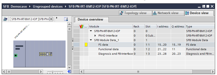
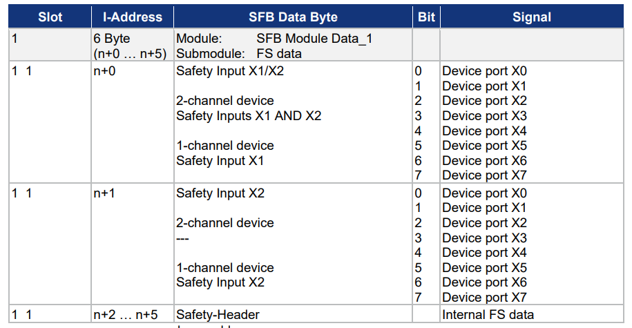
Slot1 1 Input
This is the input data mapping for Slot 1 1.
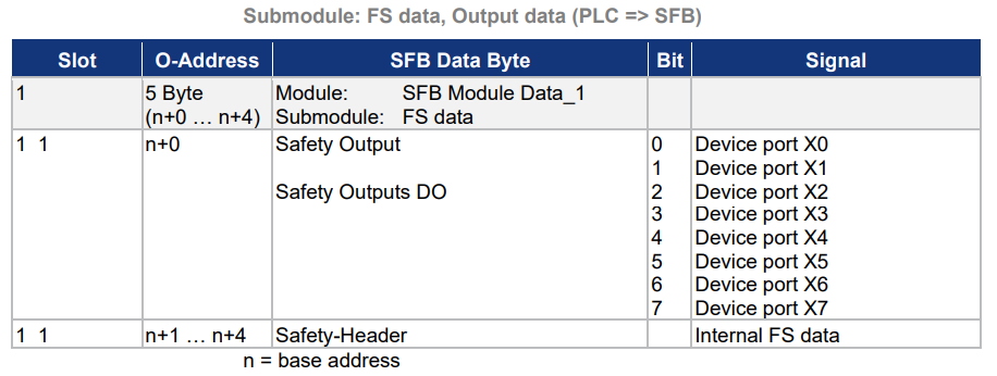
Slot1 1 Output
This is the output data mapping for Slot 1 1.
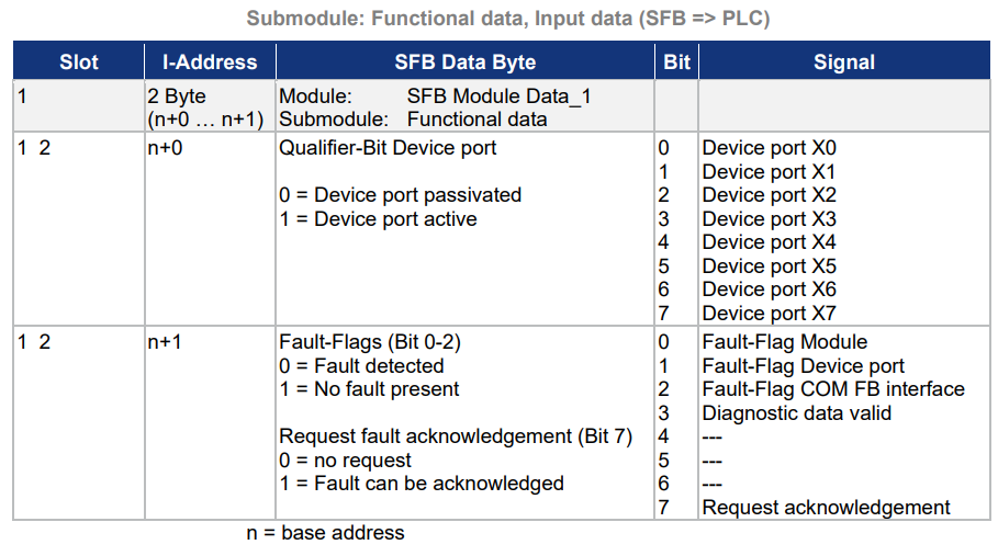
Slot1 2 Input
This is the input data mapping for Slot 1 2.
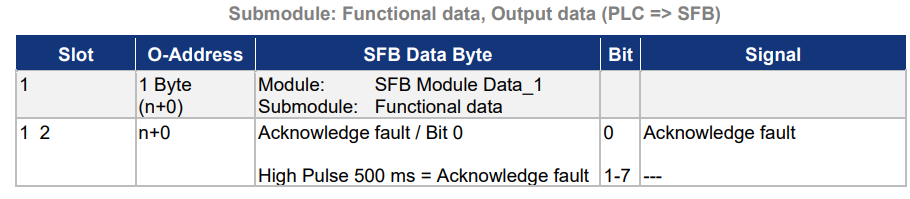
Slot1 2 Output
This is the output data mapping for Slot 1 2.
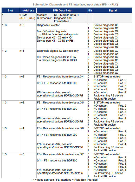
Slot1 3 Input
This is the input data mapping for Slot 1 3.
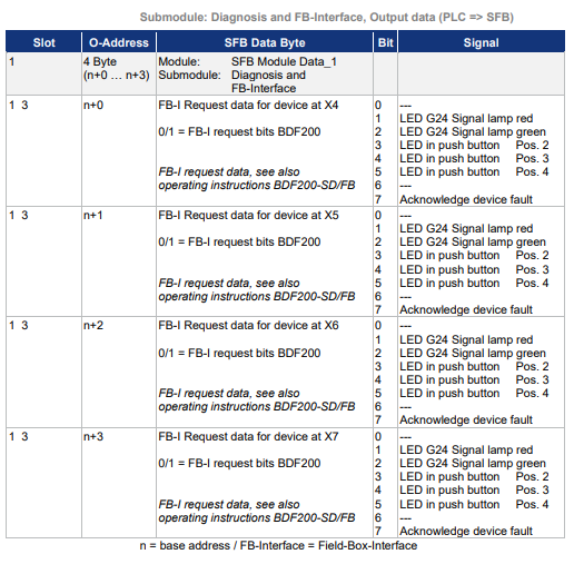
Slot1 3 Output
This is the output data mapping for Slot 1 3.
System behaviour in the event of an error
SFB-PN-V2 only supports module-granular passivation via “manual reintegration” of the F-Sub module (PROFIsafe V2.6). This reintegration is only possible when the “Device_Fault” bit changes from TRUE to FALSE.
Please note that whether an automatic restart of safety functions is permitted must be specified by the user according to the required safety requirements.
Module error
If a module error is detected, the SFB-PN responds as follows:
- In PROFIsafe, the SFB-PN is passivated and all input/output data is set to “0”.
- The red SF-LED on the SFB-PN lights up.
- The SFB-PN sets the “Module” error flag as a collective error message. (Sub module Function data Bit0, I-ADR n+1)
- The SFB-PN sends a diagnostic alarm along with an error number to the file system.
- The Err lamp on the SFB-PN flashes red.
- Usually, the red SF LED on the F-PLC also lights up (this depends on the type of connected device used).
Device port error
If a device port error is detected, the SFB-PN responds as follows:
- The device port is passivated and all input/output data is set to “0”.
- The red SF-LED on the SFB-PN lights up.
- The SFB-PN sets the “Module” error flag as a collective error message. (Sub module Function data Bit0, I-ADR n+1)
- In case of an FB-Interface communication error, the “COM FB-Interface” error flag is set. (Sub module Function data Bit2, I-ADR n+1)
- The SFB-PN sends a diagnostic alarm along with an error number to the file system.
- The Err lamp on the SFB-PN flashes red.
- The qualifier Bit for the device port where the error occurred is reset to “0”. 1 = device port operational, “0” = device port non-operational.
Errors in safety related communication to F-PLC
Errors in safety-related communication are detected by mechanisms defined in the PROFIsafe profile. The system responds according to the measures defined in the PROFIsafe profile.
- If an error occurs in safety-related communication, all input and output data of the SFB-PN are set to “0”, and the module remains in a passive state until the communication error is corrected.
- In accordance with the PROFIsafe specification, the module must be reintegrated after correcting the safety communication error.
Acknowledgement corrected faults
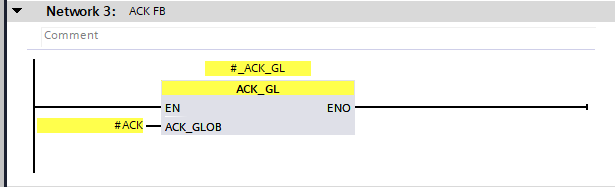
To acknowledge a Module Fault, the F function block “F_ACK_GL” [FB219] must be used. F_ACK_GL has the functionality to acknowledge all F_peripheral Faults in the F_runtime group.
Acknowledgement with “F_ACK_GL”
Module fault outgoing / can be acknowledged:
When there are no more module faults in the SB-PN,
- The Err-LED on the SFB-PN flashes green as an acknowledgment request.
- Outputs the diagnostic alarm “Fault outgoing” to the FPLC.
- By inputting ACK_GLOB to the FB F_ACK_GL, the fault can be acknowledged and the SFB-PN can be reintegrated.
- The red SF-LED on the SFB-PN turns off.
- The Err-LED on the SFB-PN lights up green.
- If there are no further abnormalities in the F module, the F-PLC clears the red SF-LED. (Depends on the type of F-PLC used)
BDF200-FB-NHK-LT-LT-LT-2875?
The modular BDF200-SD/FB control box is ideally suited for installation on safety guards of machines and plants, and the emergency stop command device is used in machines and plants as a safety command device that generates a safety signal to initiate a shutdown of hazardous movements when actuated. The emergency stop command device can only be operated when connected to a safety monitor.
Specification
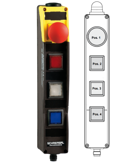
The Options that can be installed for the BDF200-FB-NHK-LT-LT-LT-2875 vary depending on the Order Number prefix, but it basically has the following features:
- Built-in FB interface for connecting to the SFB safety field box
- Position 1: E-STOP with protective collar
- Position 2: 2875 illuminated push button, color changeable
- Position 3: 2875 illuminated push button, color changeable
- Position 4: 2875 illuminated push button, color changeable
- Housing made of impact-resistant thermoplastic
- Can be installed in ergonomically favorable positions
- Can be mounted on commercially available aluminum profiles
- E-STOP with electronic OSSD
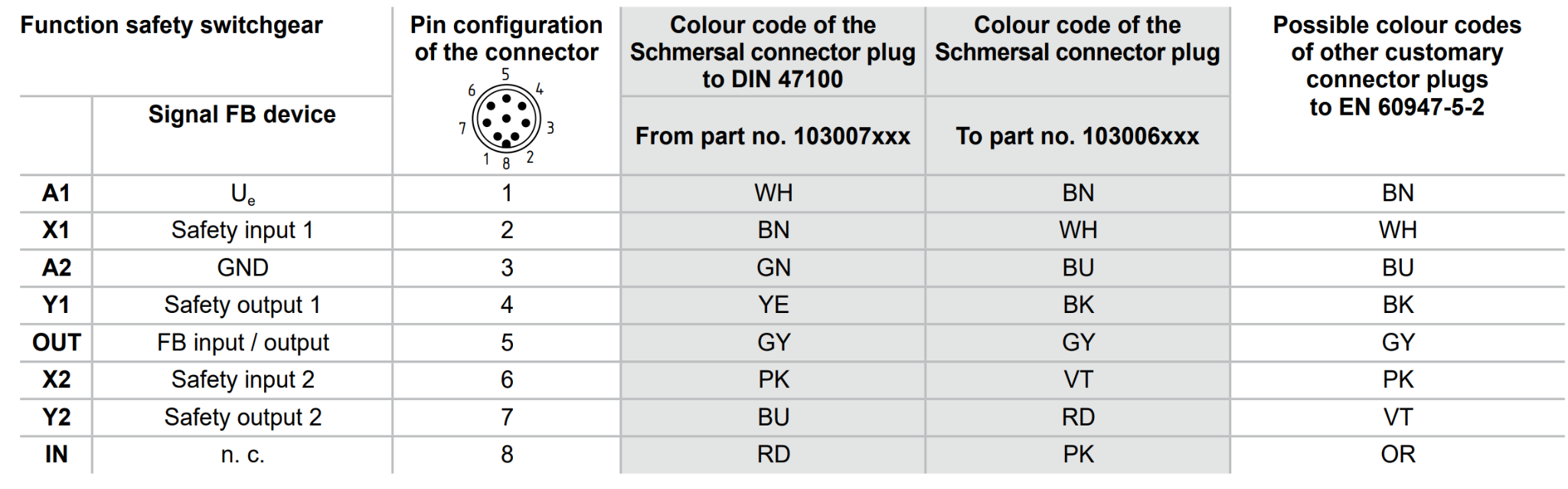
Pin Assignment
This is the Pin assignment for the BDF200-FB-NHK-LT-LT-LT-2875.
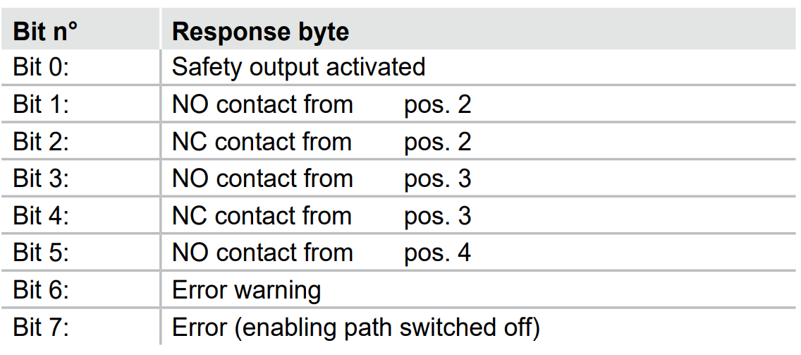
Input Mapping
This is the input data mapping for the BDF200-FB-NHK-LT-LT-LT-2875.
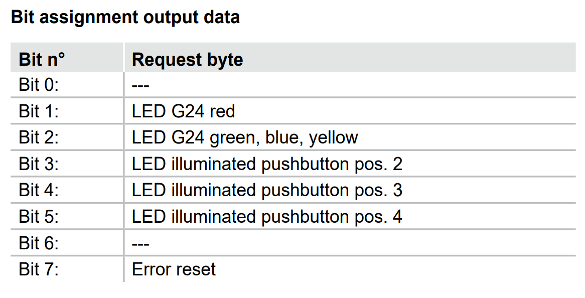
Output Mapping
This is the output data mapping for the BDF200-FB-NHK-LT-LT-LT-2875.
Safety Block
In this article, we will use the Siemens SFDOOR safety Function Block to implement safety door monitoring.
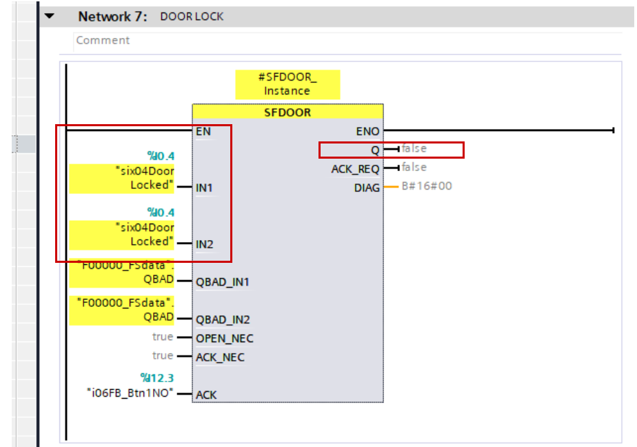
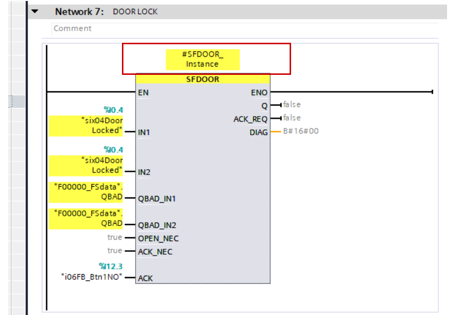
Q/IN1/IN2
The enable signal Q is reset to 0 as soon as either input IN1 or IN2 becomes signal state 0 (safety door open). The enable signal is only reset to 1 if:
- Inputs IN1 and IN2 are both in signal state 0 before opening the door (safety door is completely open).
- Then, inputs IN1 and IN2 are both in signal state 1 (safety door is closed).
- Acknowledge that the Ack signal is 1.
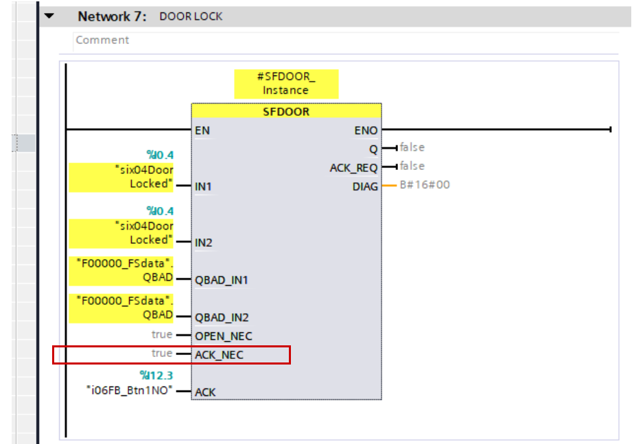
ACK_NEC
Additionally, the enable acknowledgment varies depending on the parameter assignment of the ACK_NEC input:
- If ACK_NEC = 0, acknowledgment is performed automatically.
- If ACK_NEC = 1, the enable must be confirmed on the rising edge of input JACK.
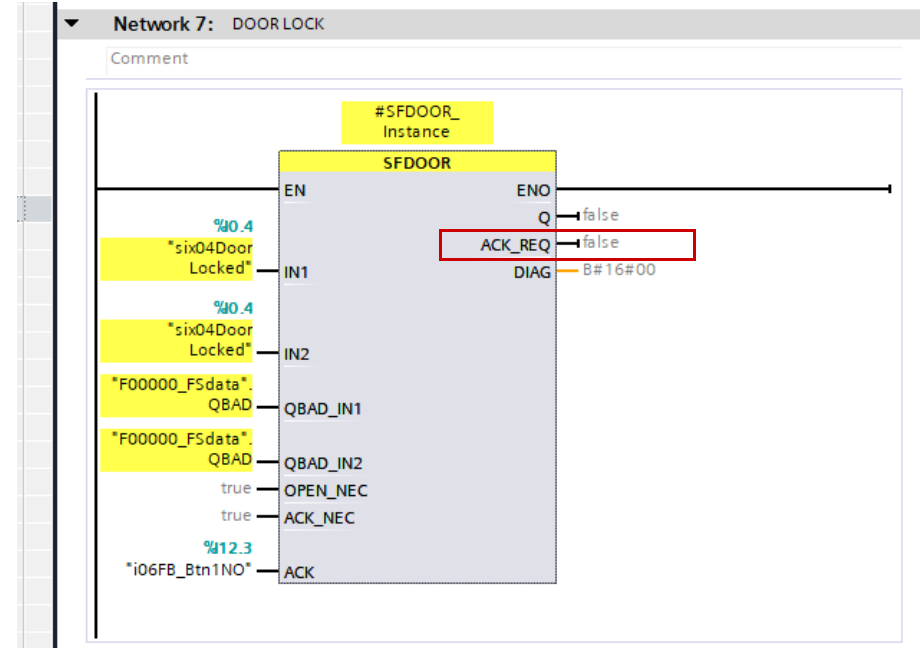
ACK_REQ
The output ACK_REQ = 1 is used to indicate that a user acknowledgment is required at the acknowledgment input ACK. This output is set to ACK_REQ = 1 as soon as the door is closed. After acknowledgment, the instruction resets ACK_REQ to 0.
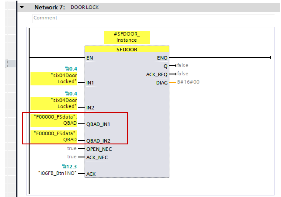
QBAD_IN1/QBAD_IN2
In order for the instruction to recognize whether inputs IN1 and IN2 have simply become 0 due to passivation of the associated F-I/O, the QBAD signal of the associated F-I/O or the QBAD_I_xx signal / inverted value status of the associated channel must be supplied to the input QBAD_IN1 or QBAD_IN2. This eliminates the need to fully open the safety door before acknowledgment if the F-I/O was passivated.
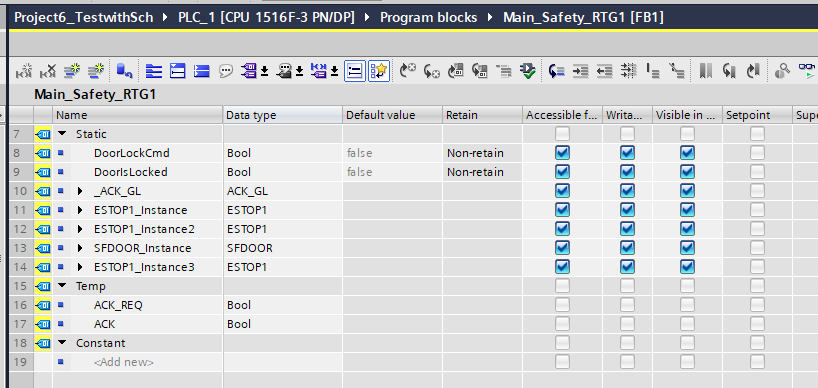
Instance
Each time SFDOOR is called, a data area where data is stored must be allocated. This can be an Instance or an independent DB.
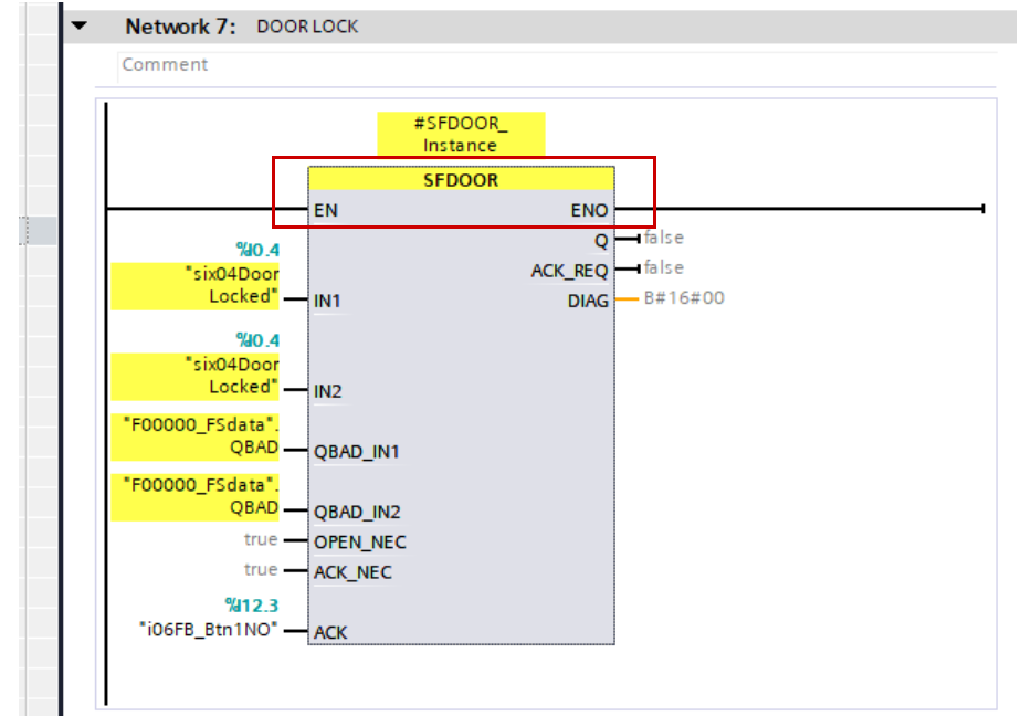
EN/ENO
Also, the enable input “EN” and enable output “ENO” cannot be connected. Therefore, this instruction is always executed (regardless of the signal state of the enable input “EN”).
Implementation
Wiring
Install Tools
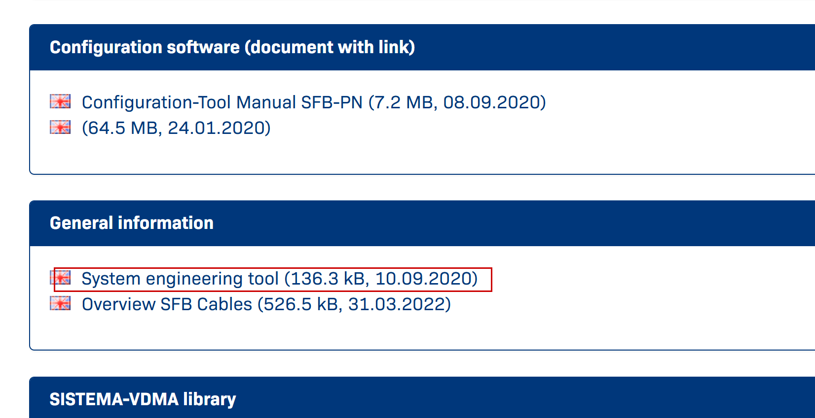
Download the tool for the SFB-PN-IRT-8M12-IOP-V2 at this link.
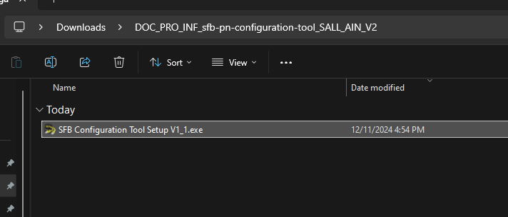
Extract the ZIP file you just downloaded and run the EXE file.
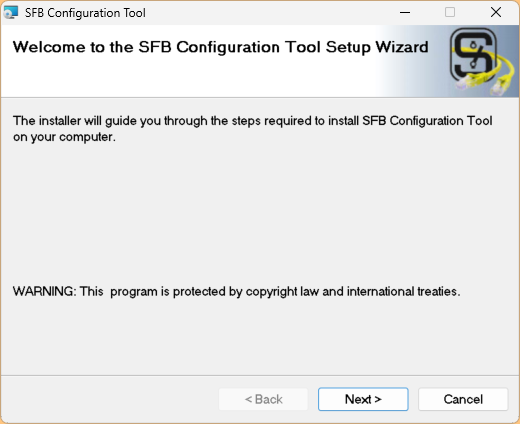
Proceed with Next>.
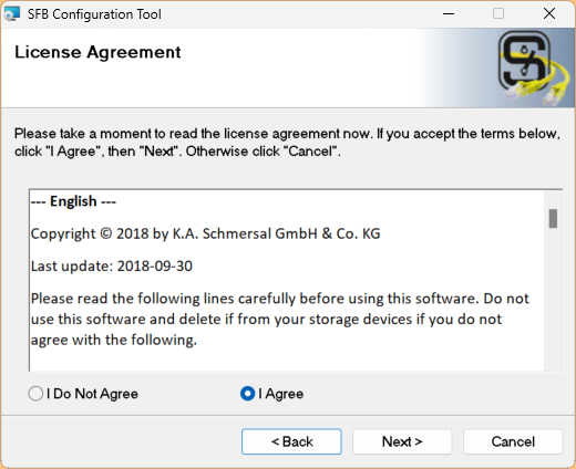
Agree to the license and proceed with Next>.
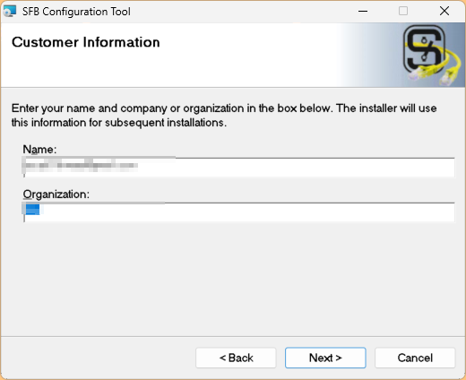
Enter company information and proceed with Next>.
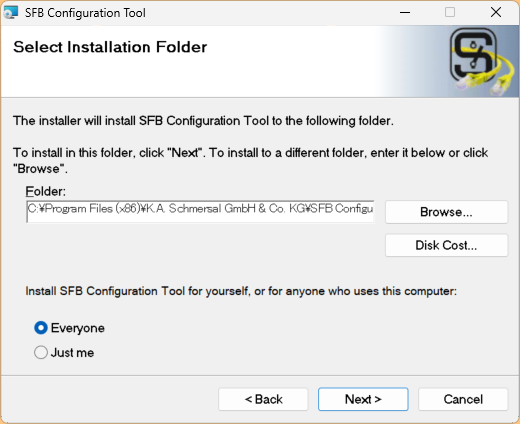
Proceed with Next>.
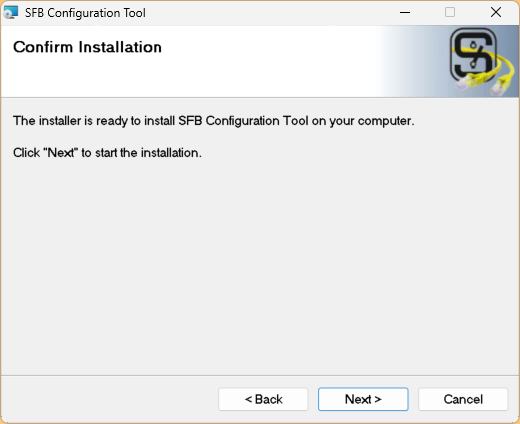
Let’s start the installation.
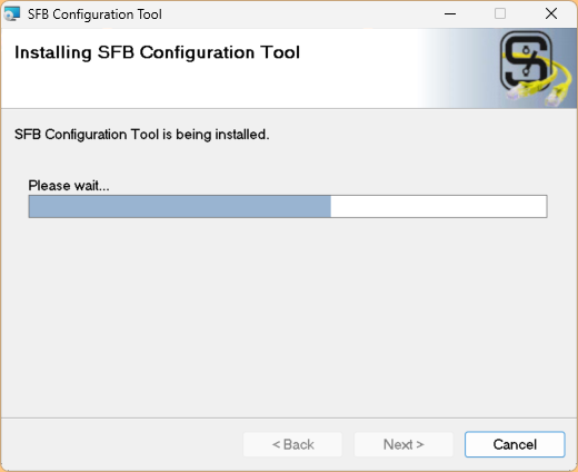
Wait for a moment…
Done! Start the SFB Configuration Tool.
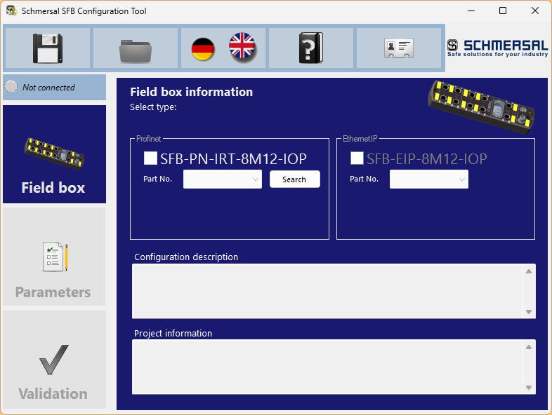
This is the configuration tool for the Schmersal SFB-PN-IRT-8M12-IOP-V2.
Download GSDML File
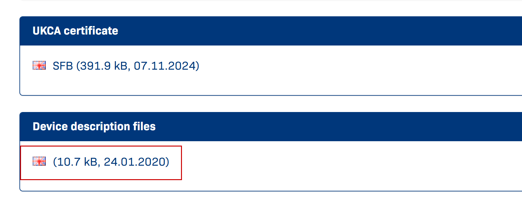
Next, please download the GSDML file at this link.
Siemens Side
First, configure the Siemens S7-1500 side.
New Project
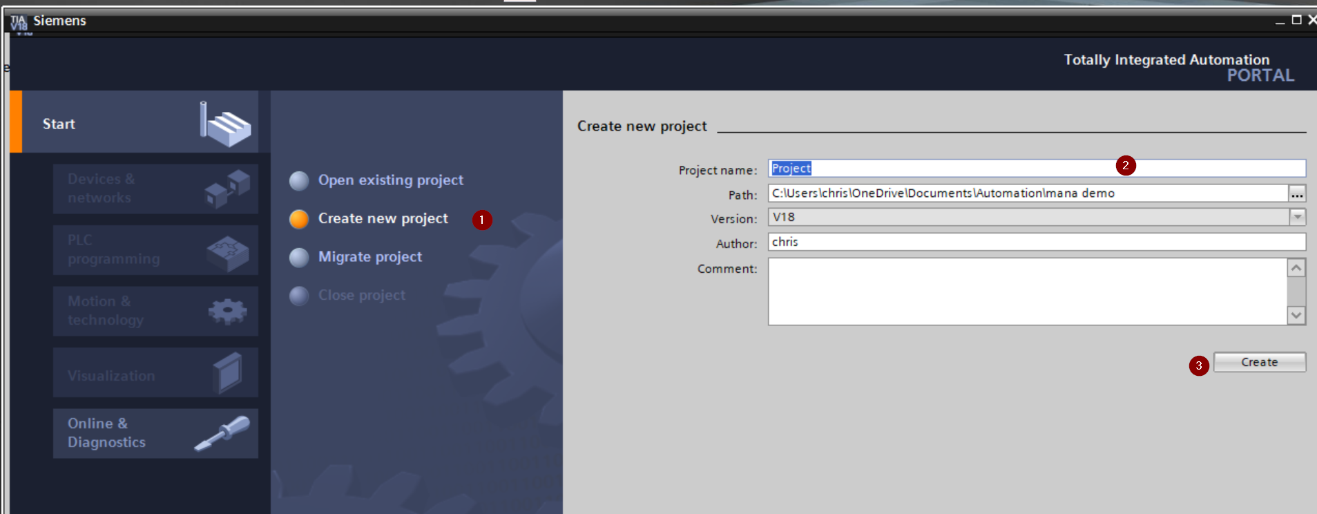
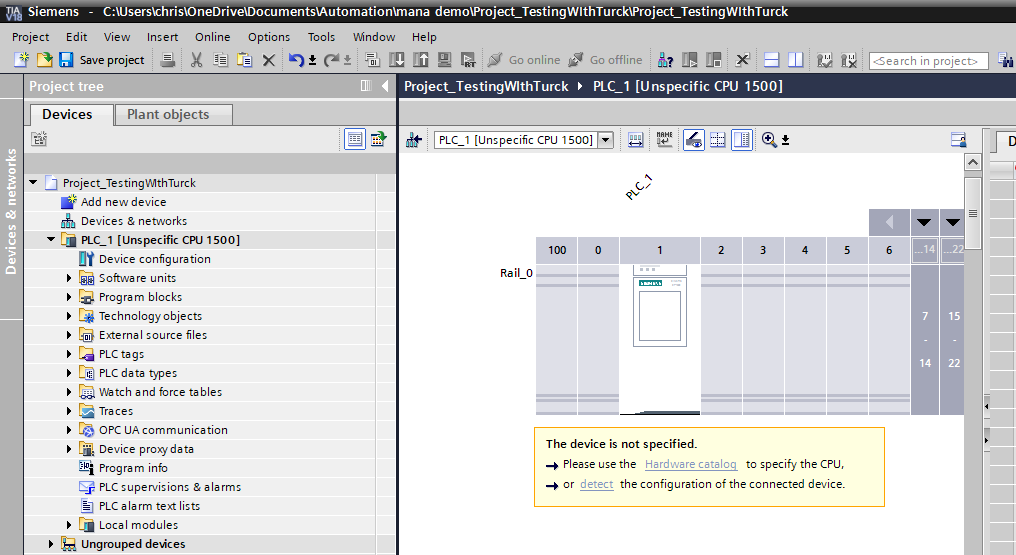
Launch TIA, then go to Start > Create new project, enter a project name, and click Create to create a new project.
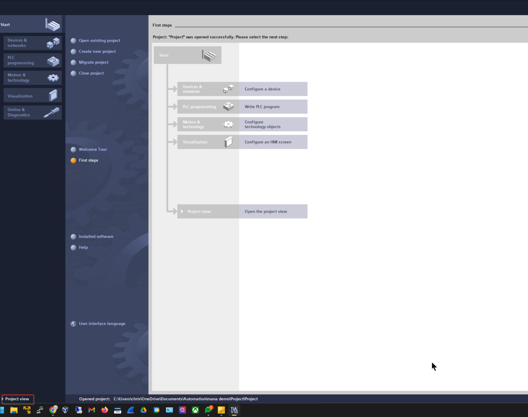
Click Project view.
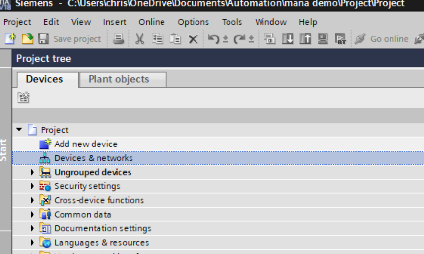
This is the TIA project creation screen.
Install GSDML
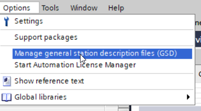
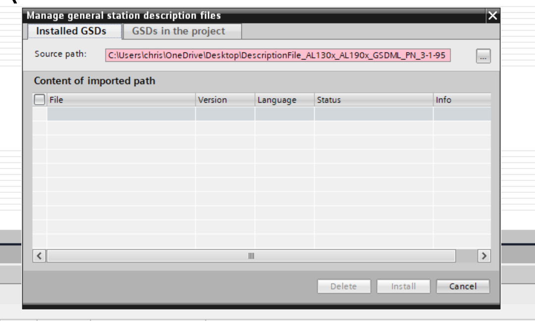
Click Options > Manage general Station description files (GSD).
The GSDML management screen will appear; click the … button.
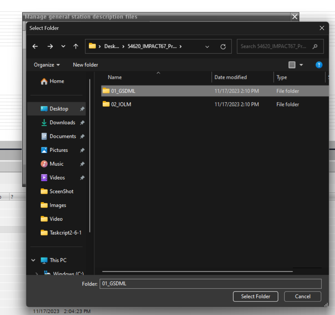
Choose the GSDML folder you downloaded earlier.
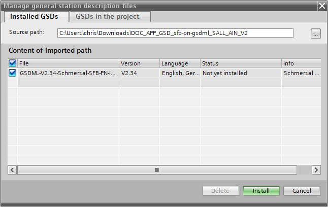
Done! The GSDML file was found. Install the GSDML file using Install.
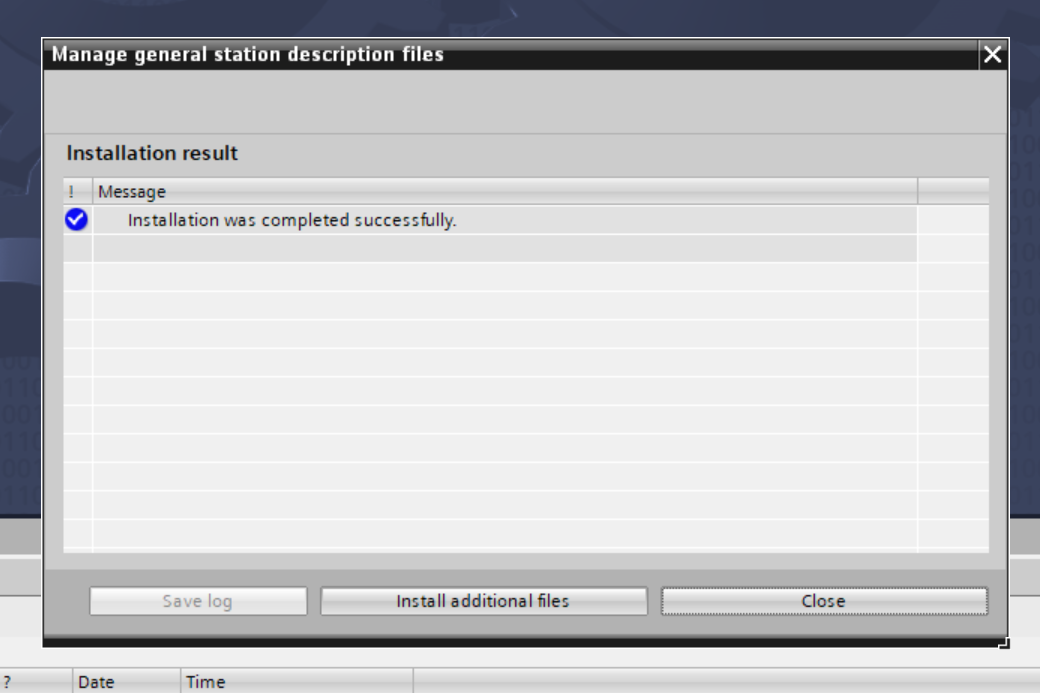
Done!
Add PLC
Add a new Siemens PLC via Project > Add new device.
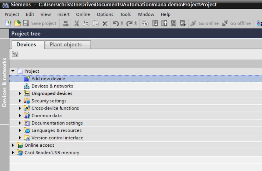
If you do not know the model of the CPU currently in use, select Unspecified CPU 1500.
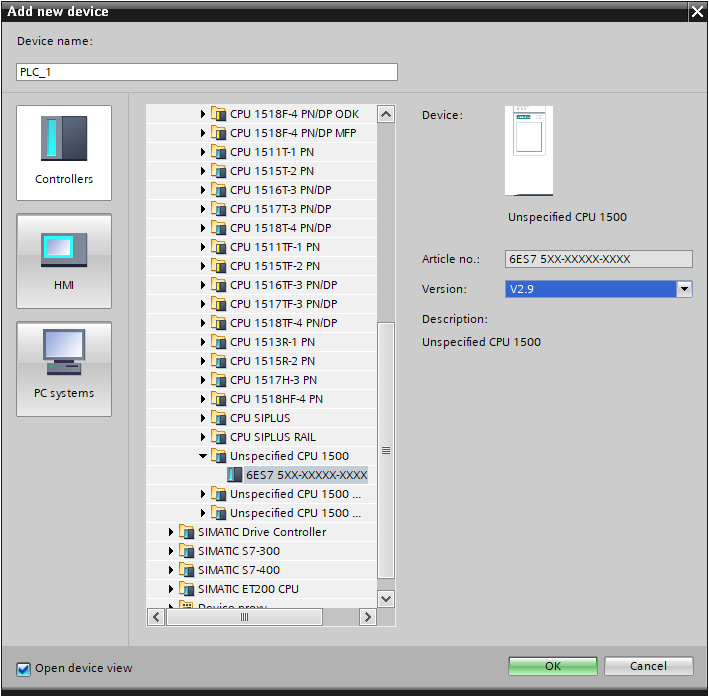
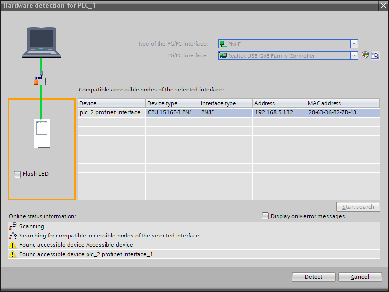
Done! Next, use “Detect” to search for the S7-1500 CPU on the network.
Click Start Search to find devices on the network.
Then, choose the appropriate CPU.
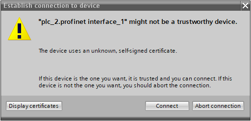
Proceed with Connect.
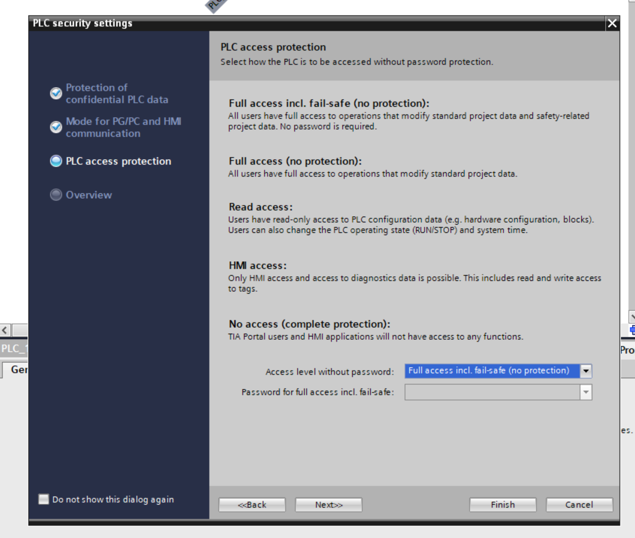
Security Setting
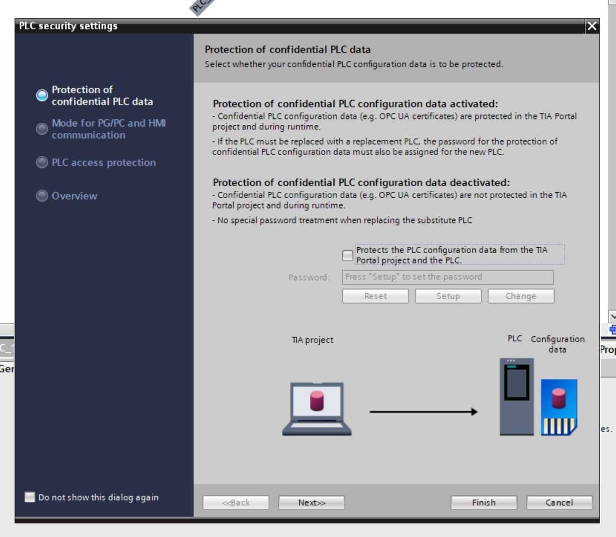
Starting from TIA V18, security settings for the CPU must be configured in advance. Since this is not an actual production environment, we will disable all security settings.
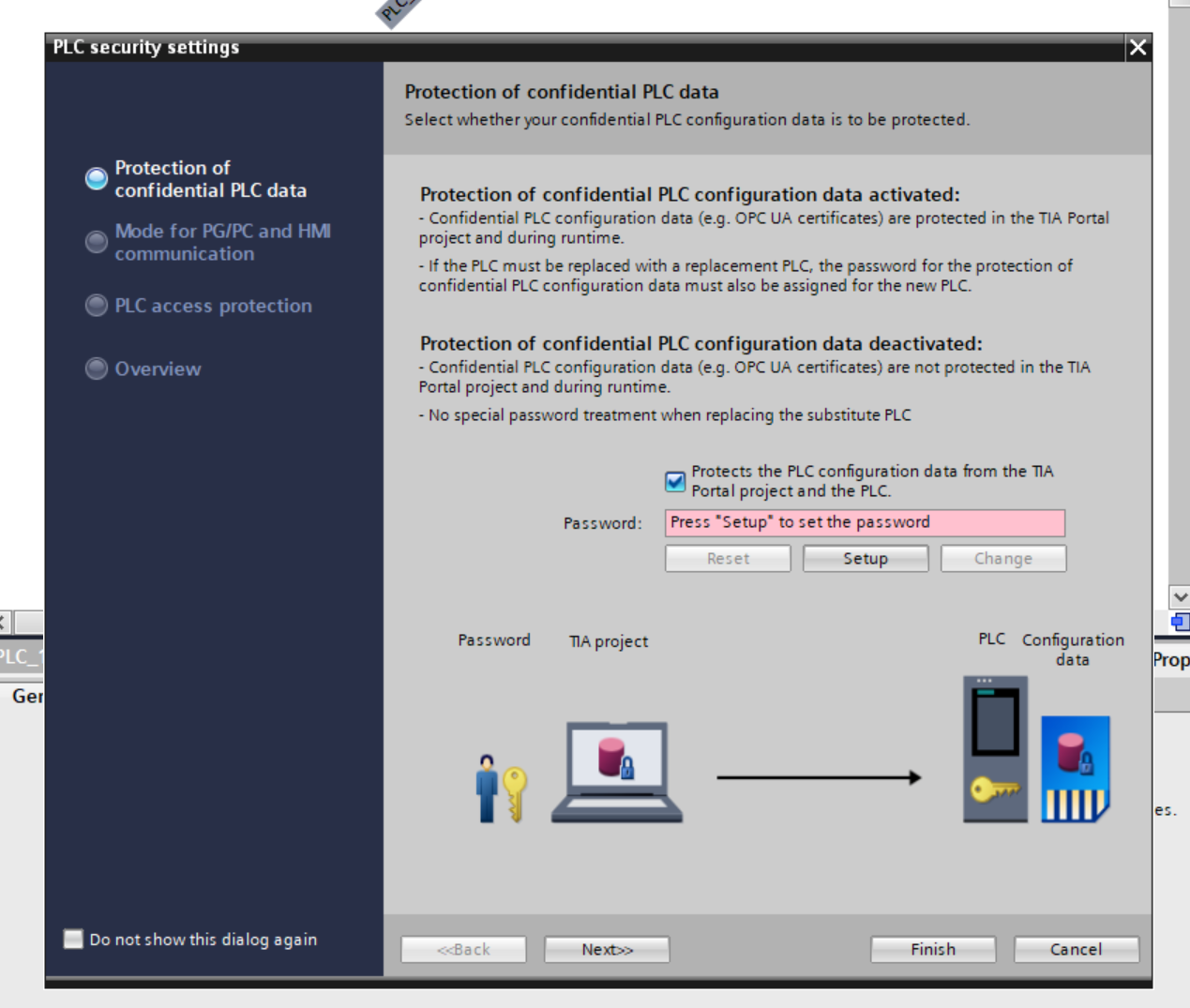
Uncheck “Protects the PLC configuration data from the TIA..” and proceed with Next>>.
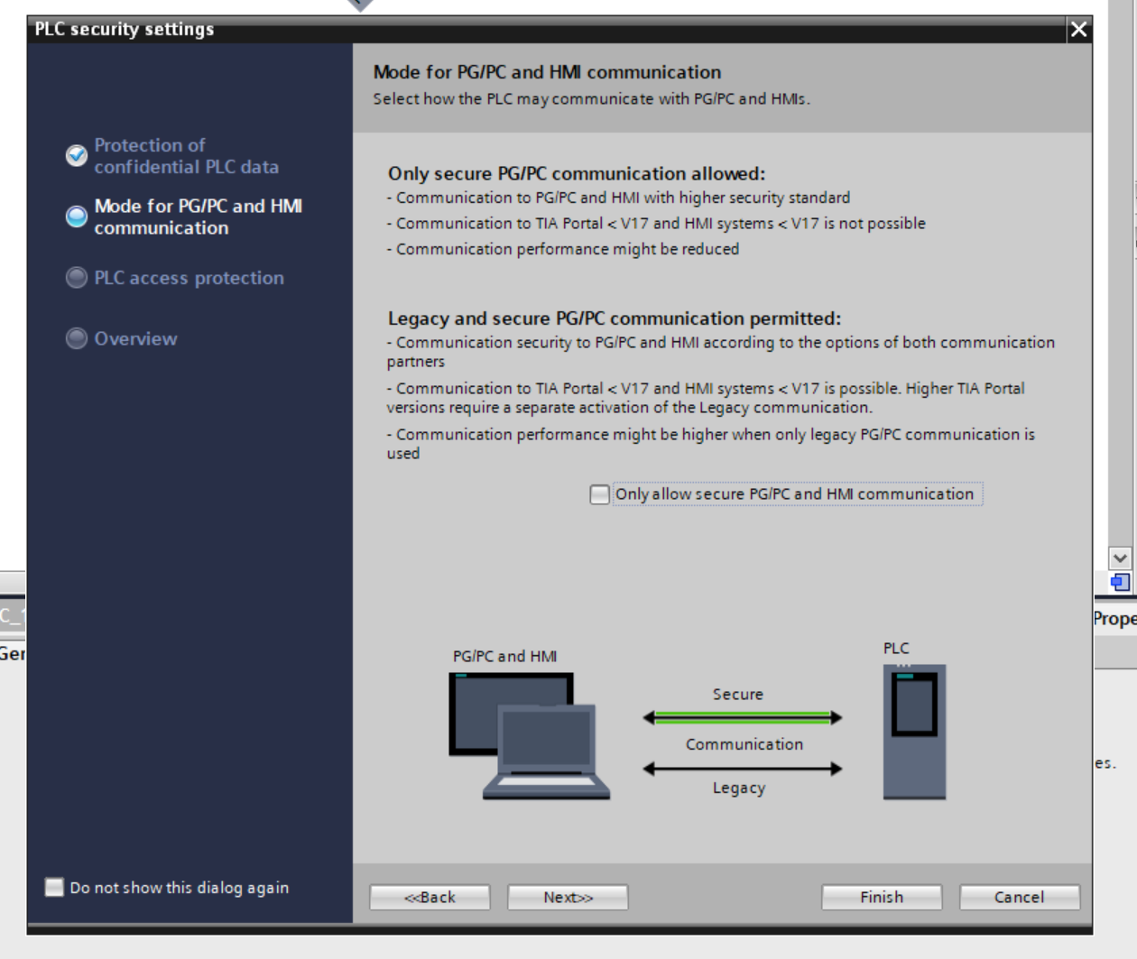
Uncheck “Only allow secure..” and proceed with Next>>.
Set to “Full access” without a password and proceed with Next>>.
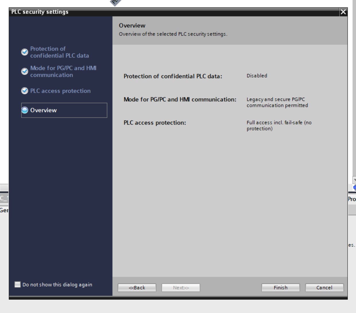
Confirm one last time and click Finish to save the settings.
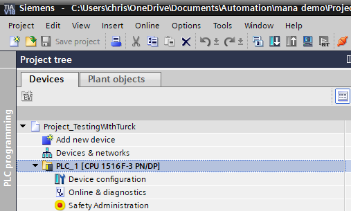
Result
Done! S7-1516F-3 has been added.
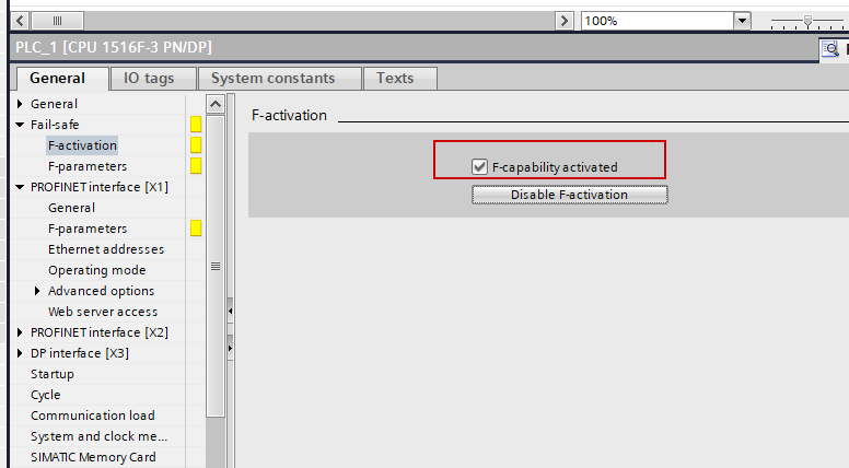
F-Activation
To enable the F-Host functionality of the S7-1516F-3, enable the Safety function under Fail-safe > F-activation.
Add Devices
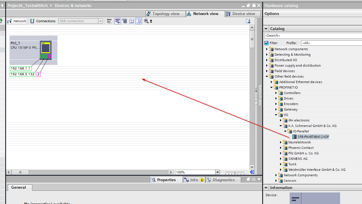
Next, add the Schmersal SFB-PN-IRT-8M12-IOP-V2 to the Profinet network.
Switch TIA to Network view and drop the SFB-PN-IRT-8M12-IOP-V2 onto the Profinet network screen.
Done! The Schmersal SFB-PN-IRT-8M12-IOP-V2 has been added.
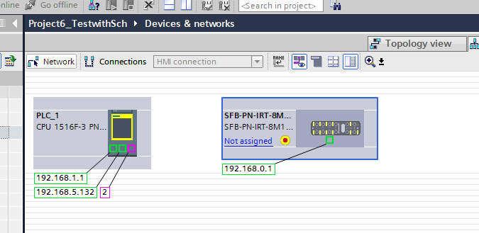
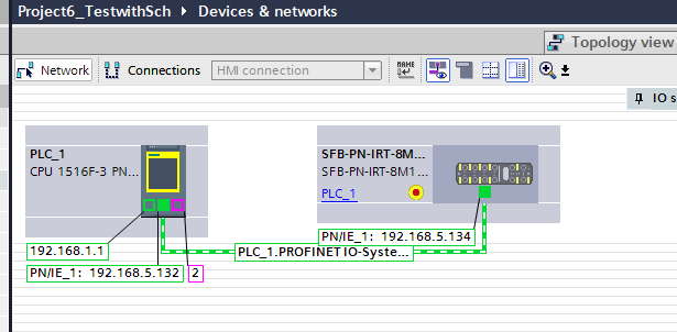
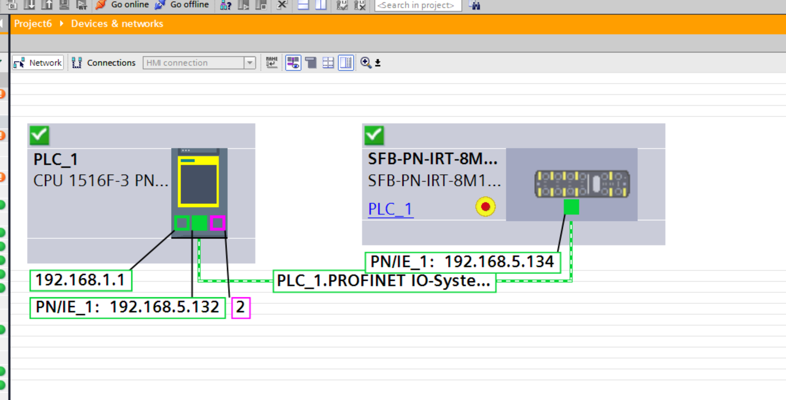
Assign Profinet
Next, set “Not Assigned > Profinet Network” so that the Schmersal SFB-PN-IRT-8M12-IOP-V2 and the Siemens PLC are on the same Profinet network.
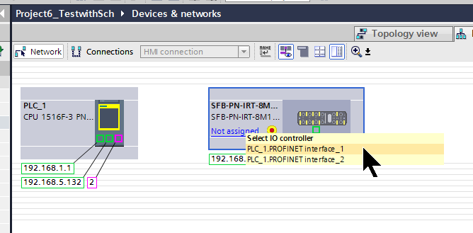
Done!
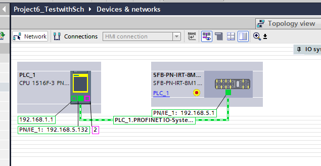
IP Address
Next, configure the IP addresses for the PLC and SFB-PN-IRT-8M12-IOP-V2 according to the application.
Configure
Next, double-click the SFB-PN-IRT-8M12-IOP-V2 to configure the parameters for the IO Device.
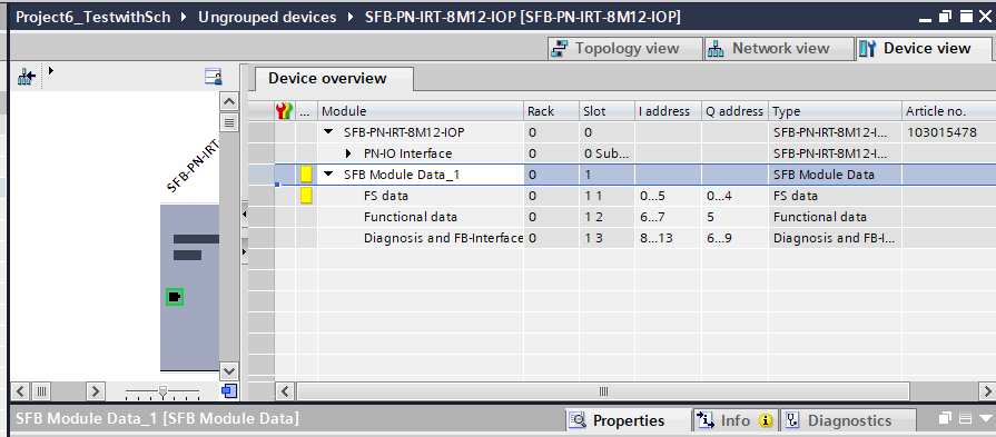
Click Module > SFB Module Data_1 > FS Data to perform Profisafe configuration.
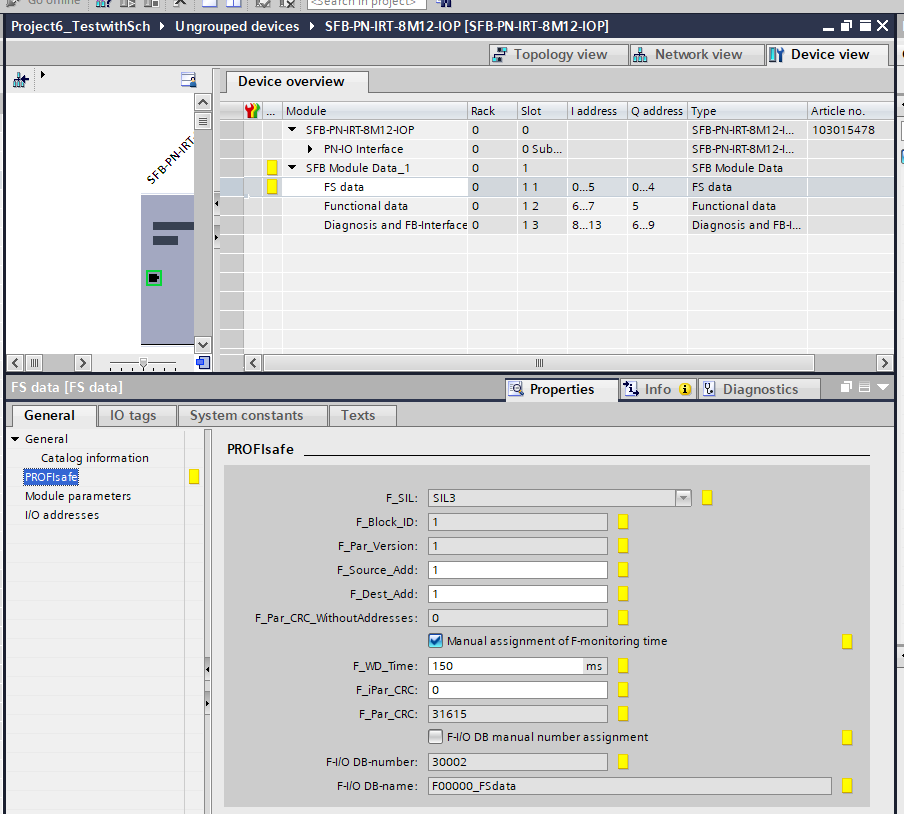
F_WD_Time
Set F_WD Time according to the application.
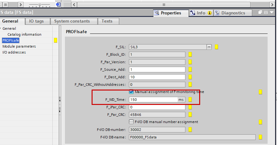
The F_WD_Time parameter defines the monitoring time for PROFIsafe communication between the F control system and the SFB-PN. If a valid F telegram is not received within F_WD_Time, the module returns to a safe state. This ensures that communication issues or failures move the F-PLC or F-device into a safe state.
Note that F_WD_Time should be set to a value that allows for communication delays. However, it should be set so that if an error occurs, the response time does not become too long.
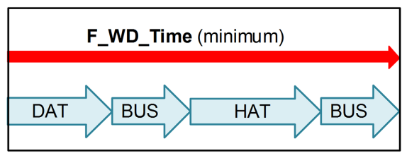
The minimum F-watchdog time F_WD_Time can be calculated as follows:
- Acknowledgment time SFB-PN-V2 (DAT): ≤ 25 ms
- Cycle time of F-runtime group in F-PLC (HAT)
- Double the cycle time of PROFINET (BUS)
- Minimum F_WD_Time: = this will be the F_WD Time setting.
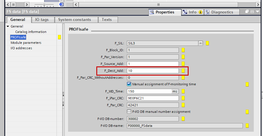
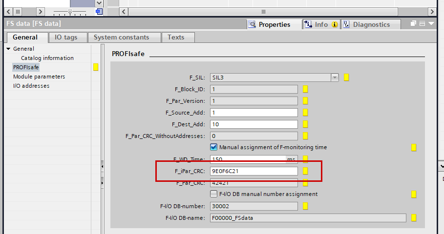
F_Dest_Add
If F_Dest_Add does not match the F-address set on the SFB-PN, a system failure (SF) will occur.
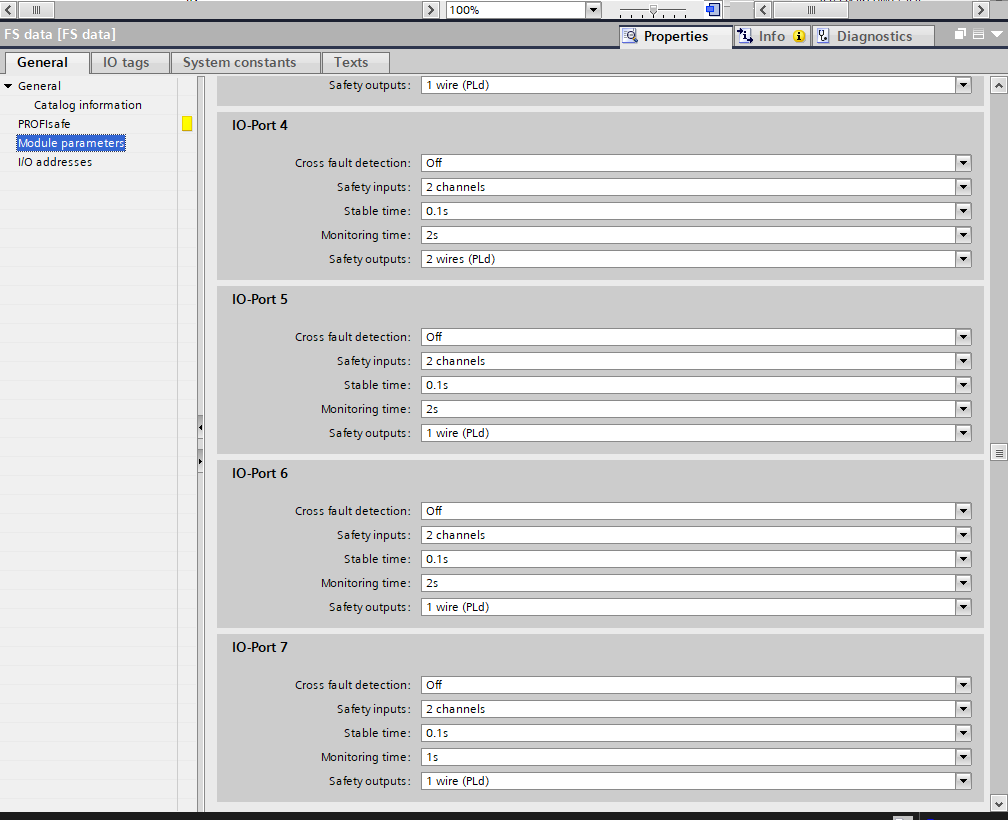
Port Parameters
Configure the parameters for each port under General > Module Parameters.
F_iPar_CRC
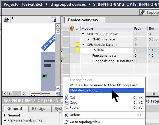
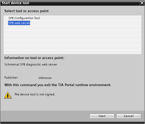
Next, to calculate the parameter CRC value for Profisafe, launch the SFB Configuration Tool via FS data > Start device tool.
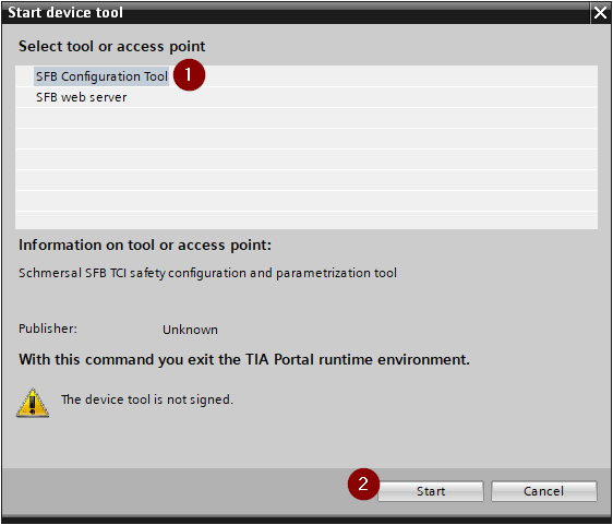
Select SFB Configuration Tool and proceed with Start.
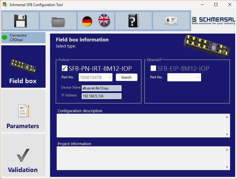
Done! The Schmersal SFB Configuration Tool was launched from TIA.
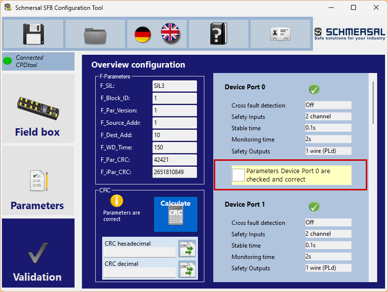
Click Validation to verify the safety parameters.
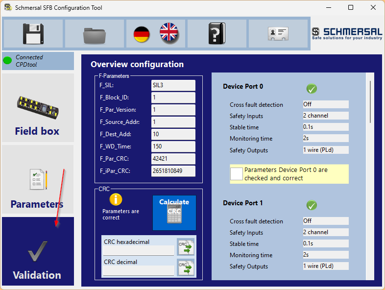
Check whether the parameters set for each port in TIA earlier are correct, and if they are, check the “Parameters Devices Port Are checked and correct” checkbox.
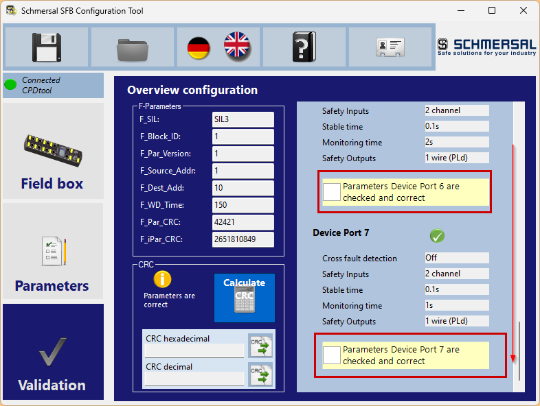
Verify parameters for all ports.
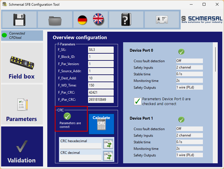
Once all parameters have been verified, the CRC field will display the text “Parameters Are correct”.
Next, calculate the CRC of the parameters.

Check the “All parameters are checked and correct.” checkbox and click Close.
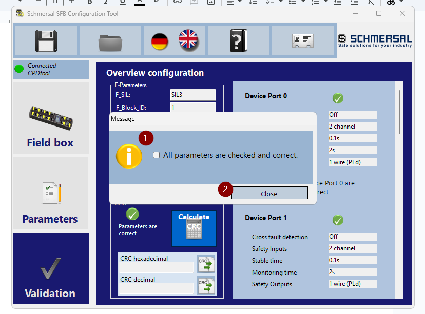
Done! The CRC value for the parameters has been calculated.
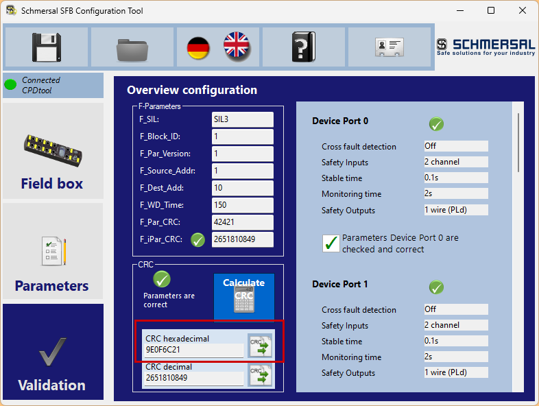
Copy that CRC value into the F_iPar_CRC field.
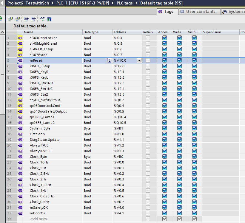
Tags
Define the variables required for the program.
Safety Program
Next, create the safety program.
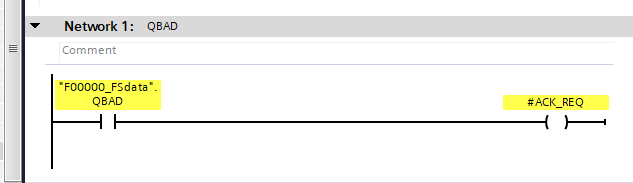
Network1
Network 1 checks whether the Schmersal SFB-PN-IRT-8M12-IOP-V2 is in a Fail Safe state using the QBAD variable.
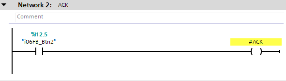
Network2
Network 2 creates an ACK Bit that can recover all devices from a Fail Safe state.
Network3
Network 3 calls the AC_GL Safety Function Block to enable devices to be recovered from Fail Safe.

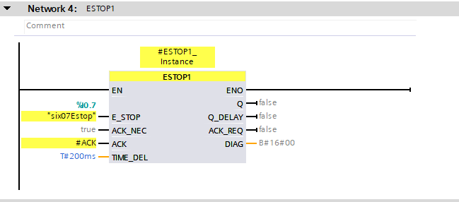
Network4
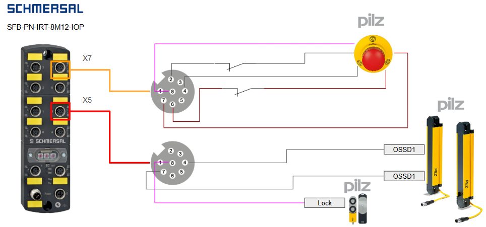
Network 4 uses the ESTOP1 Function Block to control the emergency stop connected to Port 7 of the SFB-PN-IRT-8M12-IOP-V2.
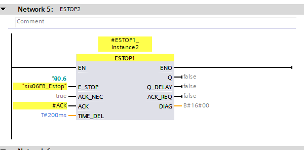
Network5
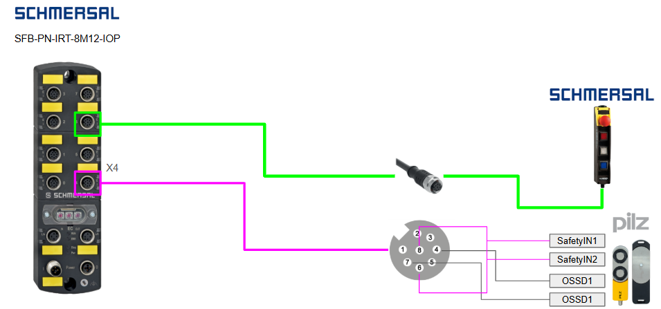
Network 5 uses the ESTOP1 Function Block to control the emergency stop on the BDF200-FB-NHK-LT-LT-LT-2875 connected to Port 6 of the SFB-PN-IRT-8M12-IOP-V2.
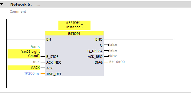
Network6
Network 6 uses the ESTOP1 Function Block to control the Pilz light curtain connected to Port 5 of the SFB-PN-IRT-8M12-IOP-V2.
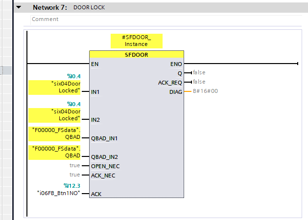
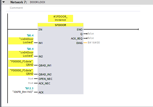
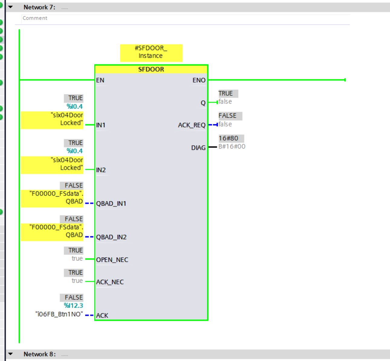
Network7
Network 7 uses the SFDOOR Function Block to control the Pilz door switch connected to Port 4 of the SFB-PN-IRT-8M12-IOP-V2.
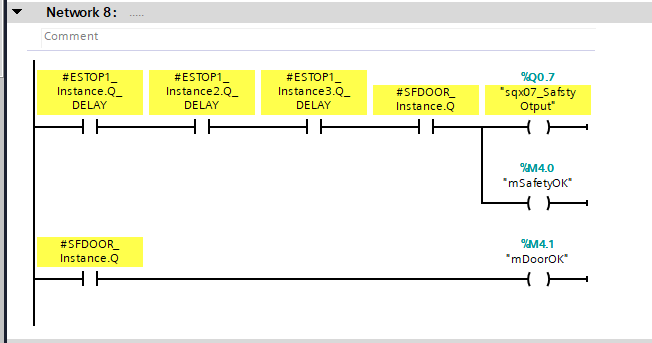
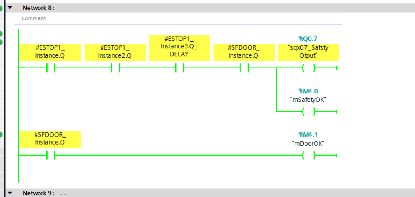
Network8
Network 8 sets the safety output of Port 7 to TRUE if all emergency stops, light curtains, and door switches are in a normal state, and also returns the normal state of the door switch to a non-safety variable.
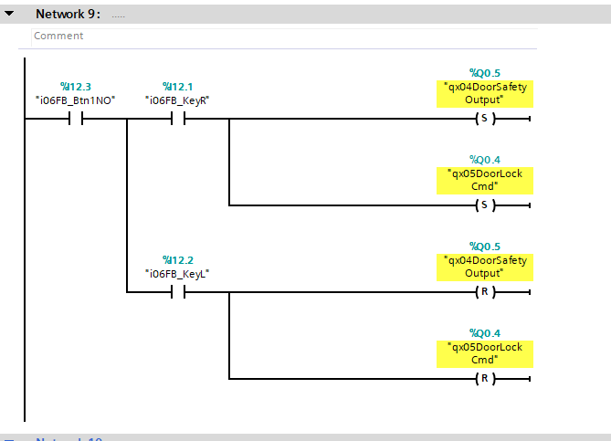
Network9
Network 9 issues state lock and unlock commands via the key switch on the BDF200-FB-NHK-LT-LT-LT-2875 at Port 6.
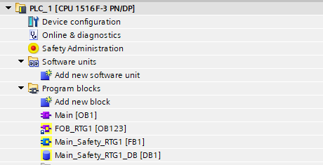
OB1
Finally, create the OB1 program.
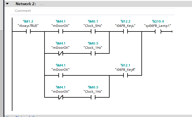
Network2
Network 2 changes the LAMP output pattern depending on whether the door is ON/OFF when the key switch of the BDF200-FB-NHK-LT-LT-LT-2875 is to the left. If the key switch is to the right, the LAMP output will light up if the door is in an OK state.
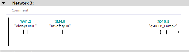
Network3
In Network 3, LAMP2 of the BDF200-FB-NHK-LT-LT-LT-2875 is lit when all door switches, emergency stops, etc. are normal.
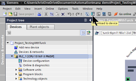
Download
Download the Hardware Configuration and program to the CPU.
Result
Done! Communication with the SFB-PN-IRT-8M12-IOP-V2 and CPU1516F-3 has been established.
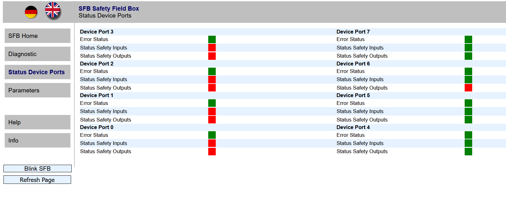
We were also able to obtain the status of the safety devices for each port installed on the SFB-PN-IRT-8M12-IOP-V2.
The SFDOOR Function Block, used for the first time in this article, also operated correctly.
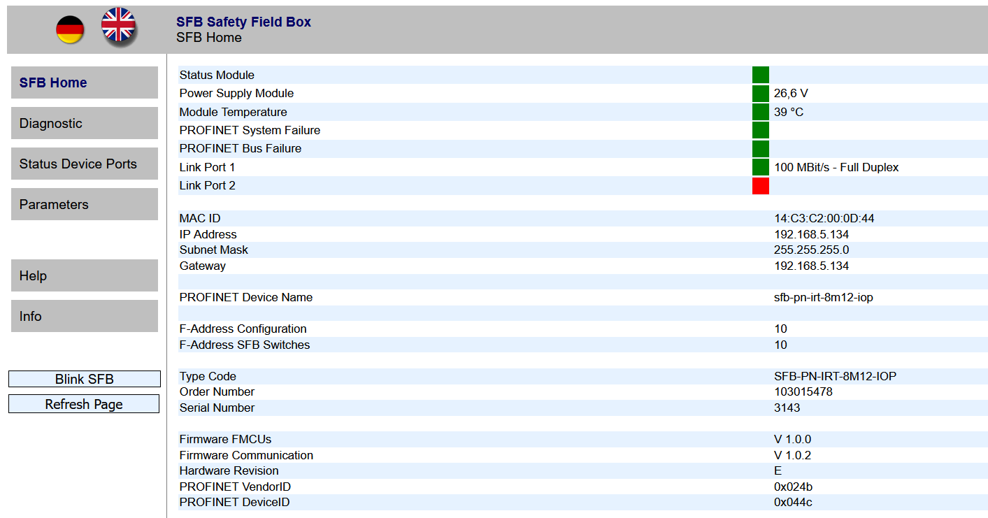
Finally, launch the SFB web server.
The status of each port could be checked on the SFB-PN-IRT-8M12-IOP-V2.
You can check the operation from this video.