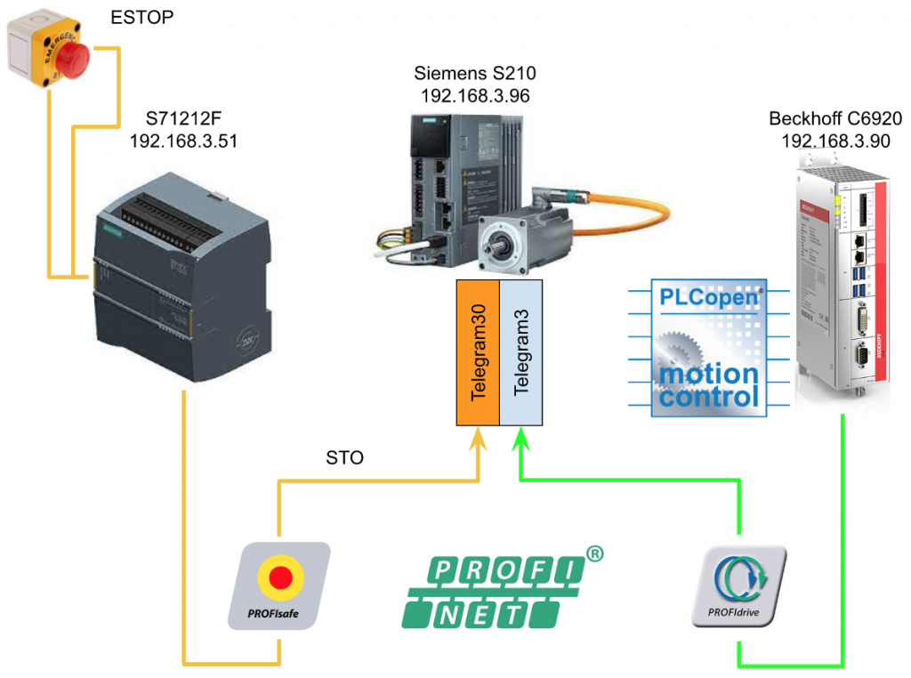
Last time, I used a Shared Device from S71200 and triggered STO of S210 via Telegram30. This time, I will use the PLCOPEN library from Beckhoff C6920 to run the S210 Drive.
Thanks!
Because of Beckhoff Japan and mana Design works that lend the devices to me – I can create this post.
Beckhoff Japan
IPC6920-005 was lent by Beckhoff Japan, a Japanese subsidiary of Beckhoff. Founded in 1980, Beckhoff Automation is a German company at the forefront of the introduction of open automation systems based on PC-based control technology.
Beckhoff Japan Corporation Beckhoff Automation Co., Ltd. established its head office in Yokohama in 2011 and the Nagoya office in 2017.

Here is the Home page of Beckhoff Japan.
https://www.beckhoff.com/ja-jp/
Mana Design Works
Siemens SINAMICS S210 was lent by Mana Design Works.
Mana Design Works is an official solution partner of Siemens ,headquartered in Osaka, and always make optimal proposals with Siemens CPUs, HMIs, Drives, Motion Controllers, and SCADA.

Here is the homepage of Mana Design works.
Video
English Version
Part4
Beckhoff.TwinCAT3 x Siemens S210 Servo Drive part4 – Idevices Configuration.EN
Part3
Beckhoff.TwinCAT3 x Siemens S210 Servo Drive part3 – PLCOPEN to Control the Drive in TwinCAT.EN
Part2
Beckhoff.TwinCAT3 x Siemens S210 Servo Drive part2 – Shared Devices,Profisafe.EN
Part1
Beckhoff.TwinCAT3 x Siemens S210 Servo Drive part1.EN
Japanese Version
Part4
Beckhoff.TwinCAT3 x Siemens S210 Servo Drive part4 – Idevices Configuration.JP
Part3
Beckhoff.TwinCAT3 x Siemens S210 Servo Drive part3 – PLCOPEN to Control the Drive in TwinCAT.JP
Part2
Beckhoff.TwinCAT3 x Siemens S210 Servo Drive part2 – Shared Devices,Profisafe.JP
Part1
Beckhoff.TwinCAT3 x Siemens S210 Servo Drive part1.JP
Reference Link
Japanese Version
Project#Beckhoff TwinCAT3 x Siemens S210 Servo Drvie_Part2 |
English Version
Project#Beckhoff TwinCAT3 x Siemens S210 Servo Drvie_Part2 |
Project#Beckhoff TwinCAT3 x Siemens S210 Servo Drvie_Part1 |
Overview
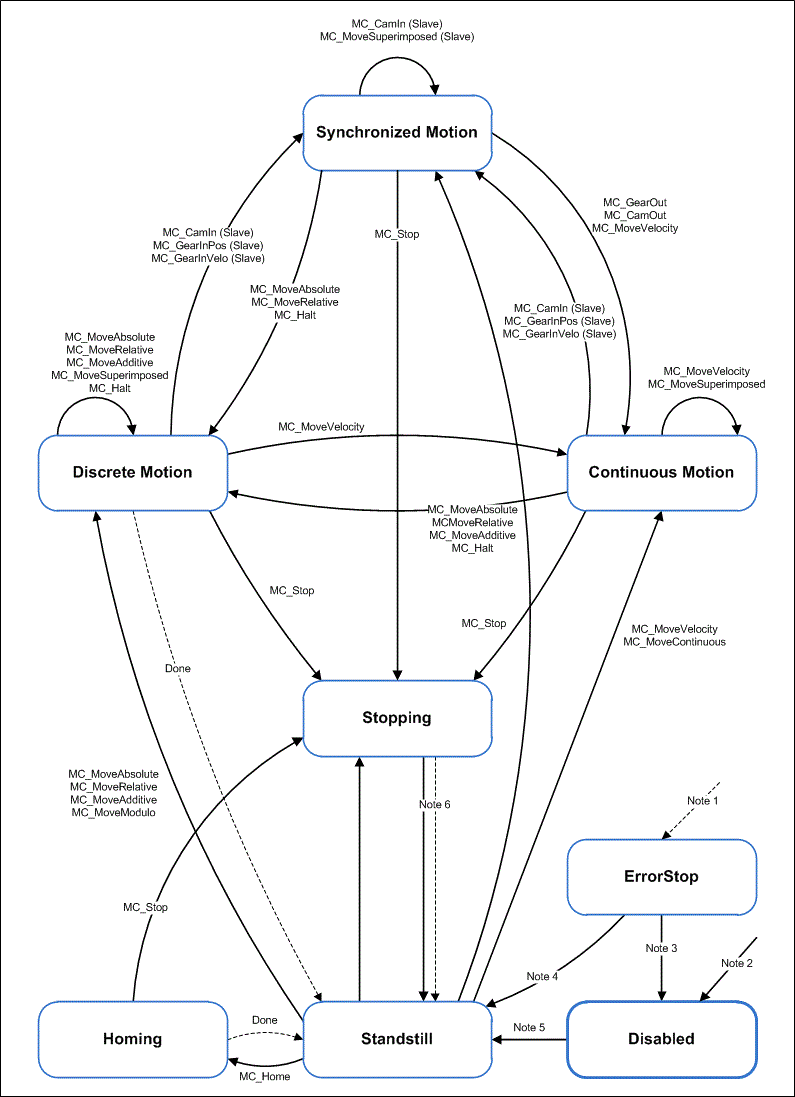
TcMC2 TwinCAT Motion Control PLC Library is created along PLCOpen’s Motion Control Function V2.0, and TwinCAT supports that library, so even different manufacturers can share Motion control programs and reduce development costs.

Rules
There are various rules and conventions when using MC Function Blocks.
Output
Busy, Done, Error, and CommandAborted are not True at the same time. If Execute Input is True, only one of the four will be True.
*Of course there are exceptions. It’s MC_Stop. Output of Done becomes True when the axis stops. But Busy and Active remain True because the axis is locked.
And when MC_Stop’s Execute becomes False, the axis’ Unlock, Busy, and Active become False.
Done
”Done”, ”InVelocity”, ”InGear” and ”InSync” of MC_Blocks become True if the command execution is successful.
CommandAborted
“CommandAborted” will be True if the Job was aborted by other MC_Blocks.
Busy
A “Busy” output indicates that the corresponding MC_Blocks are Active. MC_Blocks can be executed only when there is an edge up input in Execute, and Busy outputs are False.
Busy immediately becomes True when the MC_Blocks executes, and returns to False when the corresponding MC_Blocks executes successfully or fails.
Active
Active becomes True when MC_Blocks is executed.
Initial Status
If the corresponding MC_Blocks are not activated, Done, InGear, InVelocity, Error, ErrorID and CommandAborted are all reset at the end of Execute.
If Execute is triggered more than once within a One-Cycle, the corresponding MC_Blocks do not give Feedbacks and do nothing. Input parameters are activated by detection at startup. The command must always be retriggered if you want to change the parameters.
And if no Input parameter is passed when MC_Blocks executes, the last value passed becomes the Input parameter of MC_Blocks.
Position and Distance
Position is the location of the servo in the device. And distance is the “relative position” from the current value to the destination. For example, Station1 is at Position200 and Station2 is at Position1000. And the distance from Station1 to Station is 800.
The unit of Position and distance varies depending on the System.
Error Process
All MC_Blocks have two Error outputs.
The Error Output indicates whether an error has occurred in the corresponding MC_Blocks.
The Output called ErrorID displays the error number of the corresponding MC_Blocks.The output of “Done”, “InVelocity”, “InGear” and “InSync” will be False as long as the Error is True.Please refer to Manual for details of ErrorID.
Error Type
Note that MC_Blocks are only errors in the corresponding Block, not the axis itself (e.g. parameter errors, communication errors, etc.).
Axis errors (logical NC axis)
If the movement of the real axis causes a problem error (e.g. something is crashed) then the axis switches MC_Blocks to Error. Axis errors can be reset by MC_Reset.
Drive errors (controller)
Axis Error can usually be reset with MC_Reset.
EN and ENO
そしてMC_BlocksにあるENOのENがTrueになる限り、ENOもTrueになります。
To execute MC_Blocks, a rising pulse of ”Execute” is required, but before that, a signal of ”Enable” is required. Although it is not in ST language, LAD/FBD has an input parameter called “EN”, and MC_Blocks will not be executed unless EN becomes True.
And ENO will be True as long as EN of ENO in MC_Blocks is True.
Flow
Function Block
Data type
AXIS_REF
AXIS_REF contains AXIS information, and it is easy to imagine that it is an interface between PLC and NC. AXIS_REF is essential when using MC Block.
PlcToNc
PlcToNc is the data exchanged cyclically between the PLC and NC, MC_Blocks allows you to send commands from the PLC to the Axis. Finally Process Output is automatically sent from the PLC to the Axis.
NcToPLC
NcToPLC is data that is periodically exchanged between PLC and NC, and includes the current value, speed, status, etc. of the Axis. Axis information can be obtained from this Data Structure.
ADS
ADS Data Structure provides the necessary Interfaces to access Axis via ADS Interface.
Status
The Status Data Structure stores the Process status information of the Axis, and it should be noted that the Status does not seem to be updated periodically, so call MC_ReadStatus or ReadStatus Property of AXIS_REF to get the latest Status.
Data type E_JogMode
| MC_JOGMODE_STANDARD_SLOW | Using Standard parameters as Slow Speed Jog Mode |
| MC_JOGMODE_STANDARD_FAST | Using Standard parameters as High Speed Jog Mode |
| MC_JOGMODE_CONTINOUS | JOG at dynamics speed as long as the command is sending |
| MC_JOGMODE_INCHING | JOG moves the grand relative position |
| MC_JOGMODE_INCHING_MODULO | JOG moves the grand relative position |
Axis Function
MC_Power
MC_Power sends a software enabled signal to the Axis. When enabled, both forward and reverse rotation can be Operated OK, or either can choose the Enable Direction with Enable_Positive/Enable_Negative. You can check the current status of the corresponding Axis from the Status output.
Besides that, it is also possible to limit the actual output from Option called Override.
Of course, MC_Power can only be performed by software Enable,the hardware Enable signal of the Drive is actually required (please refer to the manufacturer of the Drive for that).
Finally, MC_Power’s Status Feedback only indicates the software control status on the PLC side, and the Drive actually has various Patterns such as digital Feedback.
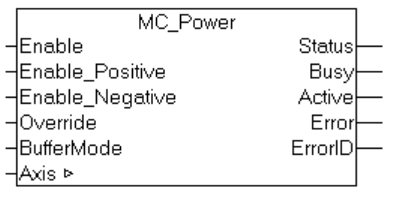
VAR_INPUT
| Variable Name | Data Type | Description |
| Enable | Bool | Software enable the Axis |
| Enable_Positive | Bool | True=Enable the Positive direction |
| Enable_Negative | Bool | True=Enable the Negative direction |
| Override | LREAL | Speed Override Setting |
| BufferMode | MC_BufferMode | Buffer Mode will trigger when the axis is reset. The Function Block waits until the axis is out of command. |
VAR_OUPUT
| Variable Name | Data Type | Description |
| Status | Bool | True=Axis is Ready |
| Busy | Bool | True=Function block is executing |
| Active | Bool | True=Function Block is executed |
| Error | Bool | True=Error |
| ErrorID | UDINT | The Error Id is shown if Error=True |
VAR_INOUT
| Variable Name | Data Type | Description |
| Axis | AXIS_REF | An Axis Object in System. It contains position, velocity, status, etc. |
MC_Reset
You can reset the Axis using this Function Block . Please refer to the manual because the reset method may differ depending on the type of drive.
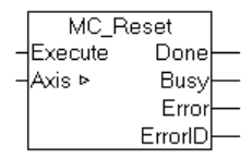
VAR_INPUT
| Variable Name | Data Type | Description |
| Execute | Bool | Edge up=Execute the Command |
VAR_OUPUT
| Variable Name | Data Type | Description |
| Done | Bool | True=Executed without error |
| Busy | Bool | True=Function Block is called and it is executing. |
| Error | Bool | True=Error |
| ErrorID | UDINT | The Error Id is shown if Error=True |
VAR_INOUT
| Variable Name | Data Type | Description |
| Axis | AXIS_REF | An Axis Object in System. It contains position, velocity, status, etc. |
MC_ReadActualVelocity
You can get the current speed of the Axis using this Function Block.

VAR_INPUT
| Variable Name | Data Type | Description |
| Enable | Bool | True=Get the Actual Velocity |
VAR_OUPUT
| Variable Name | Data Type | Description |
| Valid | Bool | True=ActualVelocity is valid |
| Busy | Bool | True=Function Block is called and it is executing. |
| Error | Bool | True=Error |
| ErrorID | UDINT | The Error Id is shown if Error=True |
| ActualVelocity | LREAL | The Actual Velocity of the axis |
VAR_INOUT
| Variable Name | Data Type | Description |
| Axis | AXIS_REF | An Axis Object in System. It contains position, velocity, status, etc. |
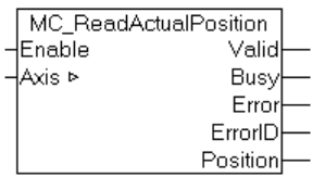
MC_ReadActualPosition
You can get the current position of the Axis using this Function Block.
VAR_INPUT
| Variable Name | Data Type | Description |
| Enable | Bool | True=Get the Actual Position |
VAR_OUPUT
| Variable Name | Data Type | Description |
| Valid | Bool | True=Position is valid |
| Busy | Bool | True=Function Block is called and executing |
| Error | Bool | True=Error |
| ErrorID | UDINT | The Error Id is shown if Error=True |
| Position | LREAL | The Actual Velocity of the axis |
VAR_INOUT
| Variable Name | Data Type | Description |
| Axis | AXIS_REF | An Axis Object in System. It contains position, velocity, status, etc. |
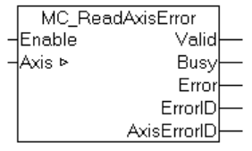
MC_ReadAxisError
You can use this function block to get the error status of an Axis.
VAR_INPUT
| Variable Name | Data Type | Description |
| Enable | Bool | True=Get the Actual Error ID |
VAR_OUPUT
| Variable Name | Data Type | Description |
| Valid | Bool | True=AxisErrorID is valid |
| Busy | Bool | True=Function Block is called and executing |
| Error | Bool | True=Error |
| ErrorID | UDINT | The Error Id is shown if Error=True |
| AxisErrorID | UDINT | Axis ErrorID |
VAR_INOUT
| Variable Name | Data Type | Description |
| Axis | AXIS_REF | An Axis Object in System. It contains position, velocity, status, etc. |
MC_ReadStatus
You can get the current state of the Axis using this Function Block. Of course, the Output parameter of the Function Block already outputs the basic status of the Axis Bit By Bit, but MC_ReadStatus also has the Axis.Status axis variable, which outputs the Axis status as a structure.

VAR_INPUT
| Variable Name | Data Type | Description |
| Enable | Bool | True=Get the Actual Axis Information |
VAR_OUPUT
| Variable Name | Data Type | Description |
| Valid | Bool | True=Function Block Output is valid |
| Busy | Bool | True=Function Block is called and it is executing. |
| Error | Bool | True=Error |
| ErrorID | UDINT | The Error Id is shown if Error=True |
| ErrorStop | Bool | Axis Condition and please reference to PlcOpen state |
| Disabled | Bool | Axis Condition and please reference to PlcOpen state |
| Stopping | Bool | Axis Condition and please reference to PlcOpen state |
| StandStill | Bool | Axis Condition and please reference to PlcOpen state |
| DiscreteMotion | Bool | Axis Condition and please reference to PlcOpen state |
| ContinousMotion | Bool | Axis Condition and please reference to PlcOpen state |
| SynchronizedMotion | Bool | Axis Condition and please reference to PlcOpen state |
| Homing | Bool | Axis Condition and please reference to PlcOpen state |
| ConstantVelocity | Bool | Axis is Operating in constant Velocity |
| Acceleration | Bool | Axis is Accelerating |
| Decelerating | Bool | Axis is Decelerating |
| Status | ST_AxisStatus | The Data structure of Status Output |
VAR_INOUT
| Variable Name | Data Type | Description |
| Axis | AXIS_REF | An Axis Object in System. It contains position, velocity, status, etc. |
Point to point motion
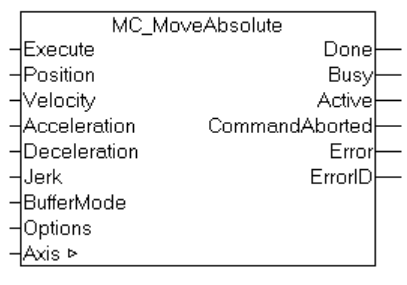
MC_MoveAbsolute
By using MC_MoveAbsolute you can operate a command to move an Axis to some “absolute” position. When the Axis reaches the target value, Done=True and otherwise CommandAborted/error. MC_MoveAbsolute is often used with Linear axes, and its move command can also be used with synchronized Slave axes.
VAR_INPUT
| Variable Name | Data Type | Description |
| Execute | Bool | Edge True=execute the command |
| Position | LREAL | The Target Position |
| Velocity | LREAL | The Max Velocity when operating |
| Acceleration | LREAL | Acceleration, if value=0, Axis Configuration parameter is used. |
| Deceleration | LREAL | Deceleration, if value=0, Axis Configuration parameter is used. |
| Jerk | LREAL | Jerk, if value=0, Axis Configuration parameter is used. |
| BufferMode | ||
| Options |
VAR_OUTPUT
| Variable Name | Data Type | Description |
| Done | Bool | True=Function Block is executed normally |
| Busy | Bool | True=Function Block is called and it is executing. |
| Active | Bool | True=Function Block is called and it is executing. |
| CommandAborted | Bool | True=Command is aborted |
| Error | Bool | True=Error |
| ErrorID | UDINT | The Error Id is shown if Error=True |
VAR_INOUT
| Variable Name | Data Type | Description |
| Axis | AXIS_REF | An Axis Object in System. It contains position, velocity, status, etc. |
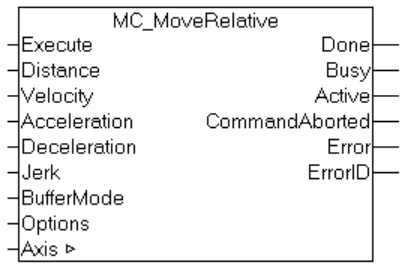
MC_MoveRelative
By using MC_MoveRelative the axes are operated as relative commands. For example, let’s say the current value is 100. Set the Distance to 250, and when the command completes it will be 100+250=350. Running it again gives 350+250=600.
VAR_INPUT
| Variable Name | Data Type | Description |
| Execute | Bool | Edge True=execute the command |
| Distance | LREAL | Target Distance |
| Velocity | LREAL | The Max Velocity when operating |
| Acceleration | LREAL | Acceleration, if value=0, Axis Configuration parameter is used. |
| Deceleration | LREAL | Deceleration, if value=0, Axis Configuration parameter is used. |
| Jerk | LREAL | Jerk, if value=0, Axis Configuration parameter is used. |
| BufferMode | ||
| Options |
VAR_OUTPUT
| Variable Name | Data Type | Description |
| Done | Bool | True=Function Block is executed normally |
| Busy | Bool | True=Function Block is called and it is executing. |
| Active | Bool | True=Function Block is called and it is executing. |
| CommandAborted | Bool | True=Command is aborted |
| Error | Bool | True=Error |
| ErrorID | UDINT | The Error Id is shown if Error=True |
VAR_INOUT
| Variable Name | Data Type | Description |
| Axis | AXIS_REF | An Axis Object in System. It contains position, velocity, status, etc. |
Manual motion
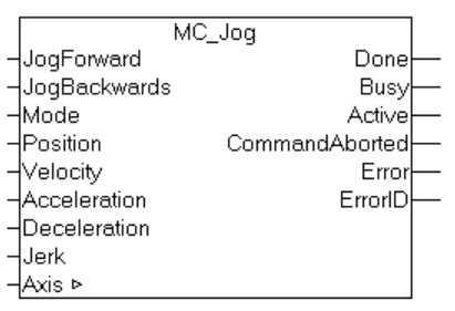
MC_Jog
You can jog the axis by using MC_Jog. Forward and reverse rotation are controlled by JogForward and JogBackwards input parameters, and Position can also set the Jog movement distance.
VAR_INPUT
| Variable Name | Data Type | Description |
| JogForward | Bool | Runs on a Positive Edge, the axis rotates positively and continues to rotate until the signal goes False.If JogForward and JogBackwards are True at the same time, JogForward takes precedence. |
| JogBackwards | Bool | Runs on a Positive Edge, the axis reverses and continues to rotate until the signal goes False.If JogForward and JogBackwards are True at the same time, JogForward takes precedence. |
| Mode | E_JogMode | |
| Position | LREAL | The amount of movement when MC_JOGMODE_INCHING is used |
| Velocity | LREAL | Velocity |
| Acceleration | LREAL | Acceleration, if value=0, Axis Configuration parameter is used. |
| Deceleration | LREAL | Deceleration, if value=0, Axis Configuration parameter is used. |
| Jerk | LREAL | Jerk, if value=0, Axis Configuration parameter is used. |
.
VAR_OUTPUT
| Variable Name | Data Type | Description |
| Done | Bool | True=Function Block is executed normally |
| Busy | Bool | True=Function Block is called and it is executing. |
| Active | Bool | True=Function Block is called and it is executing. |
| CommandAborted | Bool | True=Command is aborted |
| Error | Bool | True=Error |
| ErrorID | UDINT | The Error Id is shown if Error=True |
VAR_INOUT
| Variable Name | Data Type | Description |
| Axis | AXIS_REF | An Axis Object in System. It contains position, velocity, status, etc. |
Implementation
Add Library
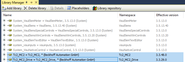
Please Insert Tc2_MC2 and Tc2_Drive in the Reference.
Program
Data Type
eDUT_Mode
Here is an enum structure data type for the Auto and Manual Operate mode.
| {attribute ‘qualified_only’} {attribute ‘strict’} TYPE eDUT_Mode : ( Auto := 1 ,Manual:=2 ); END_TYPE |
DUT_MC_Commands_Paras
Here is an enum structure data type for the positioning parameters – Velocity and Position.
| TYPE DUT_MC_Commands_Paras : STRUCT Position :LREAL; Velocity :LREAL; END_STRUCT END_TYPE |
DUT_S210_HMI_PL
Here is the Data Unit Type for the Siemens S210 Servo HMI Display.
| TYPE DUT_S210_HMI_PL : STRUCT Status :ST_AxisStatus; ActualPosition :LREAL; ActualVelocity :LREAL; ActualStation :DINT; Status_MC_Power :UDINT; Status_MC_Reset :UDINT; Status_MC_Jog :UDINT; Status_MC_Abs :UDINT; Status_MC_Rel :UDINT; ActualStationColors :ARRAY[1..9]OF BOOL; END_STRUCT END_TYPE |
DUT_S210_HMI_PB
Here is the Data Unit Type for the Siemens S210 Servo HMI Operation.
| TYPE DUT_S210_HMI_PB : STRUCT bReset :BOOL; bStart2Abs :BOOL; bStart2Rel :BOOL; bJogFw :BOOL; bJogBw :BOOL; bHome :BOOL; PosTable :ARRAY[0..9]OF LREAL; StationCmd :DINT; AbsVelocity :LREAL; RelVelocity :LREAL; RelDistance :LREAL; JogVelocity :LREAL; END_STRUCT END_TYPE |
DUT_S210_HMI
Here is the Data Unit Type that groups the operation and displays variables in a Variables.
| TYPE DUT_S210_HMI : STRUCT ServoDriveName :STRING(30); PB:DUT_S210_HMI_PB; PL:DUT_S210_HMI_PL; END_STRUCT END_TYPE |
GVL
In GVL, we only need to define the DUT_210_HMI variables.
| {attribute ‘qualified_only’} VAR_GLOBAL RETAIN Hmis :DUT_S210_HMI; END_VAR |
Function Block
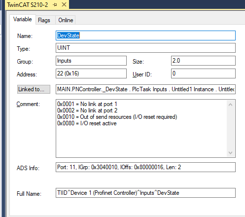
FB_PNController_Status
Here is the Function Block to link the Profinet IO Controller’s Process IO Data.
| FUNCTION_BLOCK FB_PNController_Status VAR_INPUT END_VAR VAR_OUTPUT END_VAR VAR _DevState AT %I* :UINT; _PnIoError AT %I* :UINT; _PnIoDiag AT %I* :UINT; END_VAR |
PROPERTY DevState : UINT
Here is a property to get the Devstate.
| DevState:=_DevState; |
PROPERTY PnIoDiag : UINT
Here is a property to get the PnIoDiag.
| PnIoDiag:=_PnIoDiag; |

PROPERTY PnIoError : UINT
Here is a property to get the PnIoError.
| PnIoError:=_PnIoError; |

PROPERTY PUBLIC Ready : Bool
True is returned while DevState/PnIoDiag/PnIoError are in “0”.
| Ready:= DevState =0 AND PnIoDiag =0 AND PnIoError=0 |
;
FB_PnDevices_Status
This Function Block is associated with Process IO of Profinet Device. In this article, it corresponds to Siemens’ S210 Servo Drvie.
| FUNCTION_BLOCK FB_PnDevices_Status VAR_INPUT END_VAR VAR_OUTPUT END_VAR VAR _PnIoBoxState AT %I*:UINT; _PnIOBoxDiag AT %i*:UINT; END_VAR |
PROPERTY PnIoBoxDiag : uint
Here is a property to get the Connectivity information of Profinet Devices.
| PnIoBoxDiag:=_PnIOBoxDiag; |

PROPERTY PnIoBoxState : uint
Here is a property to get the PnIo Box Status of the Profinet Devices.
| PnIoBoxState:=_PnIoBoxState; |

PROPERTY Ready : Bool
True is returned while PnIoBoxDiag/PnIoBoxState are in normal status.
| Ready:=PnIoBoxDiag = 2 AND PnIoBoxState =0 |
;
FB_Servo
This Function Block defines Servo’s Method, Property, and necessary variables. Once defined, you can extend this FB_Servo from another Function Block next time.
| FUNCTION_BLOCK FB_Servo VAR_INPUT iPNComOK :BOOL; iEnable :BOOL; END_VAR VAR_OUTPUT END_VAR VAR _Axis :AXIS_REF; END_VAR //MC_Objects VAR MC_Power :MC_Power; MC_Reset :MC_Reset; MC_Jog :MC_Jog; MC_MoveAbsolute :MC_MoveAbsolute; MC_ReadActualVelocity :MC_ReadActualVelocity; MC_ReadActualPosition :MC_ReadActualPosition; MC_ReadStatus :MC_ReadStatus; MC_ReadAxisError :MC_ReadAxisError; MC_MoveRelative :MC_MoveRelative; MC_Home :MC_Home; END_VAR |
PROPERTY ActualPosition : LReal
This Property uses the MC_ReadActualPosition Function Block to get the current position of the Axis. Returns -9999.9 if an error occurs.
| MC_ReadActualPosition( Axis:=_Axis ,Enable:=iPNComOK ); IF MC_ReadActualPosition.Valid AND NOT MC_ReadActualPosition.Error THEN ActualPosition:=MC_ReadActualPosition.Position; END_IF IF MC_ReadActualPosition.Error THEN ActualPosition:=-99999.9; END_IF |
PROPERTY ActualVelocity : LReal
This Property uses the MC_ReadActualVelocity Function Block to get the current velocity of the Axis. Returns -9999.9 if an error occurs.
| MC_ReadActualVelocity( Axis:=_Axis ,Enable:=iPNComOK ); IF MC_ReadActualVelocity.Valid AND NOT MC_ReadActualVelocity.Error THEN ActualVelocity:=MC_ReadActualVelocity.ActualVelocity; END_IF IF MC_ReadActualVelocity.Error THEN ActualVelocity:=-99999.9; END_IF |
PROPERTY AxisError : UDINT
This Property uses the MC_ReadAxisError Function Block to get the current state of the Axis. If there is an error, return the MC_ReadAxisError ErrorID as is.
| MC_ReadAxisError( Axis:=_Axis ,Enable:=iPNComOK ); IF MC_ReadAxisError.Valid AND NOT MC_ReadAxisError.Error THEN AxisError:=0; END_IF IF MC_ReadAxisError.Error THEN AxisError:=MC_ReadAxisError.AxisErrorID; END_IF |
METHOD CmdAllow2Execute : BOOL
This Method will be a command execution Interlock, the required parameters are iEnable and iPNCOMok. iPNCOMok is the Profinet communication OK signal.
| METHOD CmdAllow2Execute : BOOL VAR_INPUT END_VAR CmdAllow2Execute:=iEnable AND iPNComOK |
;
METHOD DriveAbsolutePositioning : UDINT
Here is a Method to use the MC_MoveAbsolute to operate an Absolute positioning job.
2=The job is started
3=The job is running
1=The job is done.
The Error Code of MC_MoveAbsolute is returned if an error occurred.
| METHOD DriveAbsolutePositioning : UDINT VAR_INPUT Execute :BOOL; Parameters :DUT_MC_Commands_Paras; END_VAR VAR_INST R_TRIG :R_TRIG; END_VAR MC_MoveAbsolute( Axis:=_Axis ,Execute:=Execute AND CmdAllow2Execute() AND MotionJobAllow2Execute() ,Position:=Parameters.Position ,Velocity:=Parameters.Velocity ); R_TRIG(CLK:=MC_MoveAbsolute.Execute); IF R_TRIG.Q THEN DriveAbsolutePositioning:=2; END_IF; IF MC_MoveAbsolute.Busy THEN DriveAbsolutePositioning:=3; END_IF IF MC_MoveAbsolute.Done THEN DriveAbsolutePositioning:=1; END_IF |
METHOD DriveHome : UDINT
Here is a Method to use the MC_Home to operate an Homing job.
2=The job is started
3=The job is running
1=The job is done.
The Error Code of MC_Home is returned if an error occurred.
| METHOD DriveHome : UDINT VAR_INPUT Execute :BOOL; END_VAR VAR_INST R_TRIG :R_TRIG; END_VAR MC_Home( Axis:=_Axis ,Execute:=Execute AND CmdAllow2Execute() ,Position:=0.0 ,HomingMode:=MC_HomingMode.MC_Direct ); R_TRIG(CLK:=MC_Home.Execute); IF R_TRIG.Q THEN DriveHome:=2; END_IF IF MC_Home.Busy THEN DriveHome:=3; END_IF IF MC_Home.Done THEN DriveHome:=1; END_IF IF MC_Home.Error THEN DriveHome:=MC_Home.ErrorID; END_IF |
METHOD DriveJog : UDINT
This Function Block uses MC_Jog to issue Jog commands.
1=run,
MC_Jog ErrorID is returned if Function Block error.
| METHOD DriveJog : UDINT VAR_INPUT JogForward,JogBackwards :BOOL; Parameters :DUT_MC_Commands_Paras; END_VAR DriveJog:=0; MC_Jog( Axis:=_Axis ,JogForward:=JogForward AND NOT JogBackwards AND CmdAllow2Execute() ,JogBackwards:=JogBackwards AND NOT JogForward AND CmdAllow2Execute() ,Velocity:=Parameters.Velocity ); IF MC_Jog.Active AND NOT MC_Jog.Error THEN DriveJog:=1; END_IF IF MC_Jog.Error THEN DriveJog:=MC_Jog.ErrorID; END_IF |
METHOD DriveRelateivePostioning : UDINT
Here is a Method to use the MC_MoveRelative to operate a relative positioning job.
2=The job is started
3=The job is running
1=The job is done.
The Error Code of MC_MoveRelative is returned if an error occurred.
| METHOD DriveRelateivePostioning : UDINT VAR_INPUT Execute :BOOL; Parameters :DUT_MC_Commands_Paras; END_VAR VAR_INST R_TRIG :R_TRIG; END_VAR MC_MoveRelative( Axis:=_Axis ,Execute:=Execute AND CmdAllow2Execute() AND MotionJobAllow2Execute() ,Distance:=Parameters.Position ,Velocity:=Parameters.Velocity ); R_TRIG(CLK:=MC_MoveRelative.Execute); IF R_TRIG.Q THEN DriveRelateivePostioning:=2; END_IF; IF MC_MoveRelative.Busy THEN DriveRelateivePostioning:=3; END_IF IF MC_MoveRelative.Done THEN DriveRelateivePostioning:=1; END_IF IF MC_MoveRelative.Error THEN DriveRelateivePostioning:=MC_MoveRelative.ErrorID; END_IF |
METHOD Enable : UDINT
Here is a Method to use the MC_Power to to operate a Server On Job.
1=The job is done.
The Error Code of MC_Power is returned if an error occurred.
| METHOD Enable : UDINT VAR_INPUT Execute :BOOL; END_VAR VAR_INST R_TRIG :R_TRIG; END_VAR Enable:=0; MC_Power( Axis:=_Axis ,Enable:=Execute AND CmdAllow2Execute() ,Enable_Positive:=TRUE ,Enable_Negative:=TRUE ,Override:=100.0 ); IF MC_Power.Active AND MC_Power.Status AND NOT MC_Power.Error THEN Enable:=16#1; END_IF; IF MC_Power.Error THEN Enable:=MC_Power.ErrorID; END_IF |
METHOD MotionJobAllow2Execute : BOOL
Here is a method to provide an Interlock for Motion Job.
| METHOD MotionJobAllow2Execute : BOOL VAR_INPUT END_VAR VAR Status:ST_AxisStatus; END_VAR Status:=ReadStatus(TRUE); MotionJobAllow2Execute:=Status.NotMoving AND Status.Operational AND NOT Status.HasJob; |
METHOD ReadStatus : ST_AxisStatus
Here is a method to use MC_ReadStatus to get the axis status.
| METHOD ReadStatus : ST_AxisStatus VAR_INPUT Enable :BOOL; END_VAR MC_ReadStatus( Axis:=_Axis ,Enable:=Enable AND iPNComOK ); IF MC_ReadStatus.Valid THEN ReadStatus:=MC_ReadStatus.Status; END_IF |
METHOD Reset : UDINT
This Method uses MC_Reset to reset the Axis.
1=Reset on success,
ErrorID of MC_Reset is returned if Function Block error.
| METHOD Reset : UDINT VAR_INPUT Execute :BOOL; END_VAR VAR_INST R_TRIG :R_TRIG; END_VAR MC_Reset( Axis:=_Axis ,Execute:=Execute AND CmdAllow2Execute() ); R_TRIG(CLK:=MC_Reset.Execute); IF R_TRIG.Q THEN Reset:=0; END_IF; IF MC_Reset.Done THEN Reset:=16#1; ELSIF MC_Reset.Error THEN Reset:=MC_Reset.ErrorID; END_IF |
FB_MyS210
This FB is a Function Block that controls S210. This function block is extend from FB_Servo defined earlier. I created a program for Axis Reset > Enable > Parameter Initialization > Jog Operation > Absolute Positioning > Relative Positioning.
| FUNCTION_BLOCK FB_MyS210 EXTENDS FB_Servo VAR_INPUT bServoON :BOOL; bReset :BOOL; bAutoAbsCmd :BOOL; iAutoStationCmd :UDINT; Mode :eDUT_Mode; bILJog :BOOL; bILAbs,bILRel :BOOL; END_VAR VAR_OUTPUT qActualStation :UDINT; qActualVelocity :LREAL; qActualPosition :LREAL; qStatus :ST_AxisStatus; END_VAR VAR_IN_OUT Hmis :DUT_S210_HMI; END_VAR VAR RelateiveParameters :DUT_MC_Commands_Paras; AbssoluteParameters :DUT_MC_Commands_Paras; JogParameters :DUT_MC_Commands_Paras; Status :ST_AxisStatus; AbsCmdBackup :UDINT; AbsManualCmd :UDINT; AbsManualExe :BOOL; AbsReturnValue :UDINT; AbsAutoCmd :UDINT; i :INT; TON :TON; END_VAR //Reset Reset(Execute:=bReset); //Enable Enable(Execute:=bServoON); //Parameters RelateiveParameters.Position:=Hmis.PB.RelDistance; RelateiveParameters.Velocity:=Hmis.PB.RelVelocity; AbssoluteParameters.Velocity:=Hmis.PB.AbsVelocity; JogParameters.Velocity:=Hmis.PB.JogVelocity; //ReadStatus Status:=ReadStatus(TRUE); IF Mode = eDUT_Mode.Manual THEN AbsAutoCmd:=0; DriveJog( JogBackwards:=Hmis.PB.bJogBw AND NOT Hmis.PB.bJogFw AND bILJog ,JogForward:=Hmis.PB.bJogFw AND NOT Hmis.PB.bJogBw AND bILJog ,Parameters:=JogParameters ); AbsManualExe:=Hmis.PB.bStart2Abs AND bILAbs AND NOT status.HasJob; IF AbsManualExe THEN IF Hmis.PB.StationCmd <> 0 AND Hmis.PB.StationCmd <> AbsCmdBackup THEN AbssoluteParameters.Position:= Hmis.PB.PosTable[Hmis.PB.StationCmd]; AbsCmdBackup:=Hmis.PB.StationCmd; AbsManualCmd:=Hmis.PB.StationCmd; END_IF; END_IF; DriveHome( Execute:=Hmis.PB.bHome AND NOT status.HasJob ); END_IF; IF Mode = eDUT_Mode.Auto THEN HmiCmdReset(); IF iAutoStationCmd <> 0 AND bILAbs AND NOT status.HasJob THEN AbssoluteParameters.Position:= Hmis.PB.PosTable[iAutoStationCmd]; AbsCmdBackup:=iAutoStationCmd; AbsAutoCmd:=iAutoStationCmd; END_IF END_IF AbsReturnValue:=DriveAbsolutePositioning( Execute:=AbsManualCmd <> 0 OR AbsAutoCmd <>0 ,Parameters:=AbssoluteParameters ); DriveRelateivePostioning( Execute:=Hmis.PB.bStart2Rel AND bILRel AND NOT Status.HasJob ,Parameters:=RelateiveParameters ); TON(IN:=Status.InTargetPosition,PT:=T#0.1S); IF Status.Moving THEN Hmis.PL.ActualStation:=0; END_IF IF AbsManualCmd <>0 OR AbsAutoCmd <>0 THEN IF TON.Q AND AbsReturnValue = 1 THEN IF AbsManualCmd <> 0 THEN Hmis.PL.ActualStation:=AbsManualCmd; AbsManualCmd:=0; Hmis.PB.StationCmd:=0; END_IF; IF AbsAutoCmd <> 0 THEN Hmis.PL.ActualStation:=AbsAutoCmd; AbsAutoCmd:=0; END_IF END_IF; IF AbsReturnValue >100 THEN AbsManualCmd:=0; AbsAutoCmd:=0; Hmis.PB.StationCmd:=0; END_IF END_IF; FOR i:=0 TO 9 DO Hmis.PL.ActualStationColors[i]:=FALSE; END_FOR Hmis.PL.ActualStationColors[Hmis.PL.ActualStation]:=TRUE; OutputFlash(TRUE); Hmis.PL.ActualPosition:=ActualPosition; Hmis.PL.ActualVelocity:=ActualVelocity; Hmis.PL.Status:=Status; |
METHOD HmiCmdReset : BOOL
Here is the Method to reset the HMI Command.
| METHOD HmiCmdReset : BOOL Hmis.PB.bJogBw:=FALSE; Hmis.PB.bJogFw:=FALSE; Hmis.PB.bStart2Abs:=FALSE; Hmis.PB.bStart2Rel:=FALSE; Hmis.PB.StationCmd:=0; |
METHOD OutputFlash : BOOL
Here is the Method to reflash the Output Status.
| METHOD OutputFlash : BOOL VAR_INPUT Flash:BOOL; END_VAR qActualPosition:=ActualPosition; qActualStation:=Hmis.PL.ActualStation; qActualVelocity:=Hmis.PL.ActualVelocity; qStatus:=Hmis.PL.Status; |
MAIN
The last is the Main program. Define AXIS_REF, FB_PNController_Status, FB_PnDevices_Status and FB_MyS210 Instance, etc., and finally create an Auto/Manual operation.
| PROGRAM MAIN VAR Axis :AXIS_REF; PowerOn,Reset :BOOL; END_VAR VAR PNController :FB_PNController_Status; PNDevices_S210 :FB_PnDevices_Status; S210 :FB_MyS210; Mode :eDUT_Mode; autocmd:BOOL; autosst :DINT; istep:DINT; TON :TON; END_VAR IF Mode=eDUT_Mode.Auto THEN CASE istep OF 0: TON(IN:=TRUE,PT:=T#1S); IF TON.Q THEN istep:=10; TON(in:=False); END_IF 10: autosst:=1; IF S210.qActualStation = 1 THEN istep:=15; autosst:=0; END_IF 15: TON(in:=TRUE,PT:=T#1S); IF TON.Q THEN TON(in:=FALSE); istep:=20; END_IF; 20: autosst:=2; IF S210.qActualStation = 2 THEN istep:=0; autosst:=0; END_IF END_CASE ELSE istep:=0; END_IF S210( iPNComOK:=PNController.Ready AND PNDevices_S210.Ready ,iEnable:=TRUE ,bServoON:=PowerOn ,bReset:=Reset ,Mode:=Mode ,bILAbs:=TRUE ,bILJog:=TRUE ,bILAbs:=TRUE ,bAutoAbsCmd:=autocmd ,iAutoStationCmd:=autosst ,Hmis:=GVL.Hmis ); |
Configuration
Link the AXIS_REF in your user program to the Axis Object.

Go to Settings Tab>Link to PLC to link the Axis_REF variable in your user program.
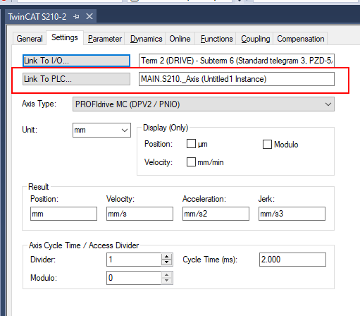
If you want to get the Flag when reaching the TargetPosition for positioning, set the Position Range Monitor and Target Position Monitoring to True from the Parameters Tab.

Screen
Now let’s create the screen. This time there is only one S210 Drive,if there are multiple screen parts, there is no problem in copying> pasting> changing the HMI variable, but it is time-consuming, and if you change the screen, you have to change them one by one. It’s inefficient. This time, I will introduce a method that does not take much time, how to create a structured screen.
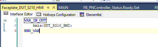
Faceplate_DUT_S210_HMI
While you create a screen, can you see a VAR_IN_OUT area in the Interface Editor? You can define INOUT parameters. This time, the purpose is to operate and display the S210 HMI, so DUT_S210_HMI is declared.
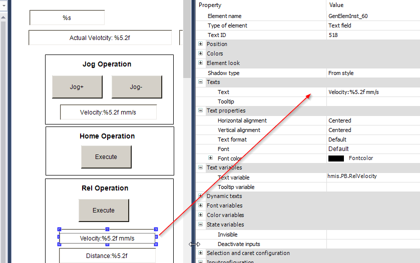
Next, let’s create a screen by arranging displays and buttons.

Assign the INOUT parameter like hmis.PB.RelVelocity directly to the Text Variable.
Main Screen
Once the structured screen is created, the next step is to add it to the Main Screen. You can see the Faceplate_DUT_S210_HMI created earlier in Toolbox>Current Project.
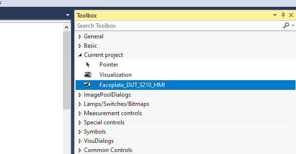
Please drop it on the main screen.
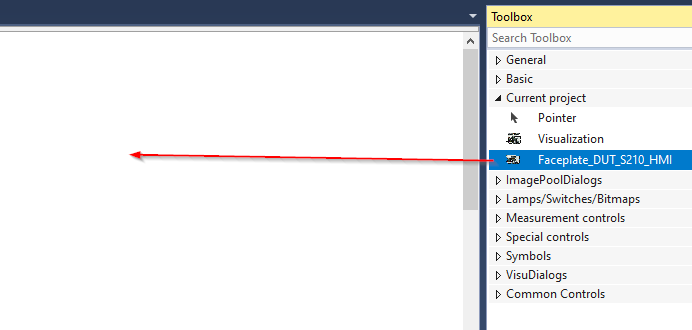
Assign the faceplate to the variables in your user program.

In my tutorial,GVLs>GVL>Hmis is used.

Download Source File
https://github.com/soup01Threes/TwinCAT3/blob/main/Beckhoff%20TwinCAT%20S210_Part3.tnzip