This is the sixth episode of the Pilz PSS4000 introduction. Previously, we introduced Resource global variables, VAR_TEMP and Instruction list in Resource global variables, but when using Pilz, it is common for states such as ESTOP and Door Switch to be sent to a higher-level PLC.
Pilz also has Profinet or Ethernet/IP functionality, so in this article we will start up the Ethernet/IP Adapter and explain the steps to exchange data with the Scanner on the Beckhoff TwinCAT3 and Mitsubishi RJ71EIP91 Ethernet/IP module from scratch.
Let’s start!
Thanks!
This article was made possible thanks to Beckhoff Automation K.K., Beckhoff’s Japanese subsidiary, and Pilz Japan for lending us their equipment. Thank you very much.
ベッコフ日本法人ベッコフオートメーション株式会社
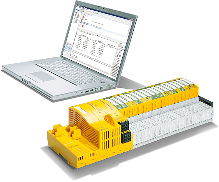
IPC6920-005 was lent to us by Beckhoff Automation Japan K.K. Beckhoff Automation was founded in 1980 and is a German company at the forefront of the introduction of open automation systems based on PC-based control technology.
Beckhoff Automation K.K., the Japanese subsidiary of Beckhoff, established its head office in Yokohama in 2011 and its Nagoya office in 2017.

This is the homepage of Beckhoff Automation K.K., Beckhoff’s Japanese subsidiary.
Best regards.
https://www.beckhoff.com/ja-jp/
PILZ
PILZ supports FA sites as a total solution supplier with solutions in safety and automation technology, guaranteeing the safety of people as well as machines and the environment, and how safely machines and equipment can be operated. PILZ has 42 subsidiaries and branches worldwide and is active in various sectors such as packaging, the automotive industry, robotic applications, as well as wind power and railway technology.

Office:
ピルツジャパン株式会社
〒222-0033
横浜市港北区新横浜3-17-5
いちご新横浜ビル 4階
HP
Reference Link
Ethernet/IP With PSS 4000
For non-safety Data connections, an Ethernet/IP Adapter can be used and accessed by other Scanners; Pilz’s PS4000 supports this functionality.
- Ethernet/IP Scanner and Implicit message, periodic IO data exchange on Port 2222.
- As an Explicit Message Server, it exchanges Explicit data with Explicit messages and is supported by the following Objects。
- 0x01 Identity Object
- 0x02 Message Router Object 0x02
- 0x04 Assembly Object
- Output Assembly Object Instance
- Input Assembly Object Instance
- 0x06 Connection Manager Ob
- 0xF5 TCP/IP Object
- 0xF6 Link Object
0x04 Assembly Object
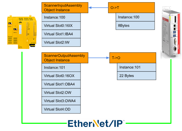
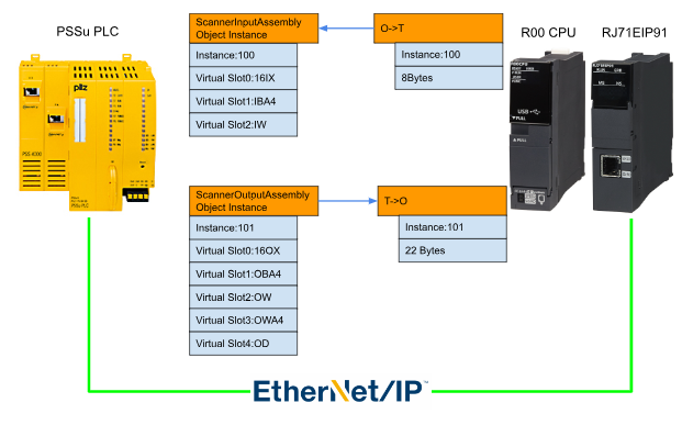
Assembly Object 0x04 is the Assembly Object used when exchanging data between a Pilz Ethernet/IP Adapter and an Ethernet/IP Scanner from another manufacturer (in this article, a Beckhoff TwinCAT3 and a Mitsubishi RJ71EIP91).
Output Assembly Object Instance
The Scanner Output Assembly Object Instance is the Output data on the Scanner side and the Input on the Pilz side. The data exchange size is variable, so when building a Pilz Ethernet/IP Adapter on the Scanner side, please adjust the exchange size.
The Adapter can be built by Inserting Virtual Modules from the Ethernet/IP Editor of Pilz. (16IX, IB, IW, ID, etc.)
Attribute ID
| Attribute ID | Name | Description |
| 1 | Not Supported | Not Supported |
| 2 | Not Supported | Not Supported |
| 3 | Data | Output data on the Scanner side. |
| 4 | Size | Its data size |
Virtual Module
| Module | Data Type | Application |
| 16IX | ARRAY[0..15] OF BOOL | Virtual Ethernet/IP bit moduleBool array of 16-bit length |
| IBAn | ARRAY[0..(n-1)]OF BYTE | Virtual Ethernet/IP Byte Array ModuleByte array of length N, N=2,4,8,16,32,64OBA2 would be ARRAY[0… (1)]OF BYTE. |
| IW | WORD | Virtual Ethernet/IP Word Array Module |
| OWAn | ARRAY[0..(n-1)OF WORD | Virtual Ethernet/IP Word ModuleWord array of length N, N=2,4,8,16,32,64OBW2 would be ARRAY[0… (1)]OF WORD. |
| OD | DWORD | Virtual Ethernet/IP DWORD Array Module |
Input Assembly Object Instance
The Scanner Input Assembly Object Instance is the Input data on the Scanner side and the Output on the Pilz side. The data exchange size is variable, so when building the Pilz Ethernet/IP Adapter on the Scanner side, the exchange size must be adjusted.
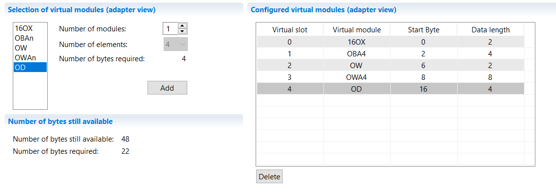
Virtual Modules can be Inserted and Adapters can be built from the Pilz Ethernet/IP Editor. (16OX, OB, OW, OD, etc.).
Attribute ID
| Attribute ID | Name | Description |
| 1 | Not Supported | Not Supported |
| 2 | Not Supported | Not Supported |
| 3 | Data | Input data on the Scanner side. |
| 4 | Size | Its data size |
Virtual Module
| Module | Data Type | Application |
| 16OX | ARRAY[0..15] OF BOOL | Virtual Ethernet/IP bit moduleBool array of 16-bit length |
| OBAn | ARRAY[0..(n-1)]OF BYTE | Virtual Ethernet/IP Byte Array ModuleByte array of length N, N=2,4,8,16,32,64OBA2 would be ARRAY[0… (1)]OF BYTE. |
| OW | WORD | Virtual Ethernet/IP Word Array Module |
| OWAn | ARRAY[0..(n-1)OF WORD | Virtual Ethernet/IP Word ModuleWord array of length N, N=2,4,8,16,32,64If OBW2, then ARRAY[0… (1)]OF WORD. |
| OD | DWORD | Virtual Ethernet/IP DWORD Array Module |
Implementation-Pilz Side
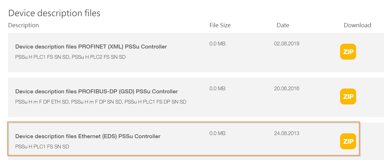
Download the EDS Files
Download the EDS File of Pilz PSSU PLC from the LINK below.
Configure the Ethernet/IP Adapter
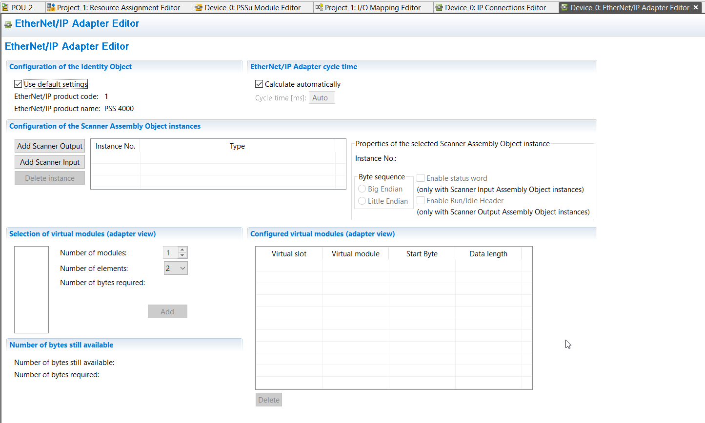
Click Hardware configuration>Your Device>EtherNet/IP Adapter.
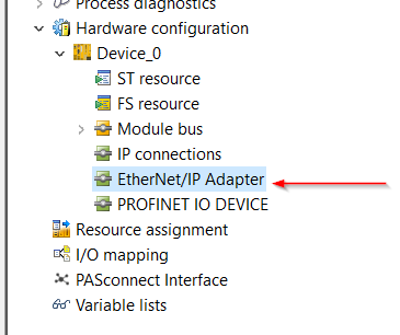
The Pilz CPU Ethernet/ip Adapter build screen is now displayed.
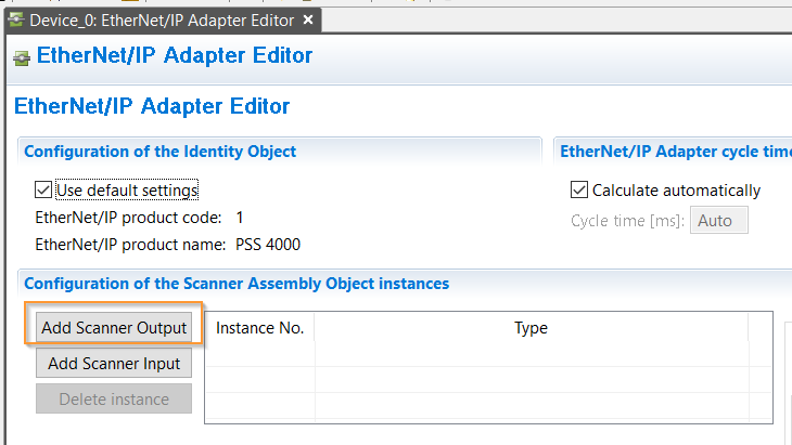
Scanner Output
First, build from the Scanner Output side: click on Add Scanner Output.
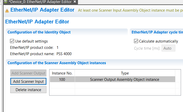
A Scanner Output Assembly Object Instance with Instance No. 100 has been added.
Mappings
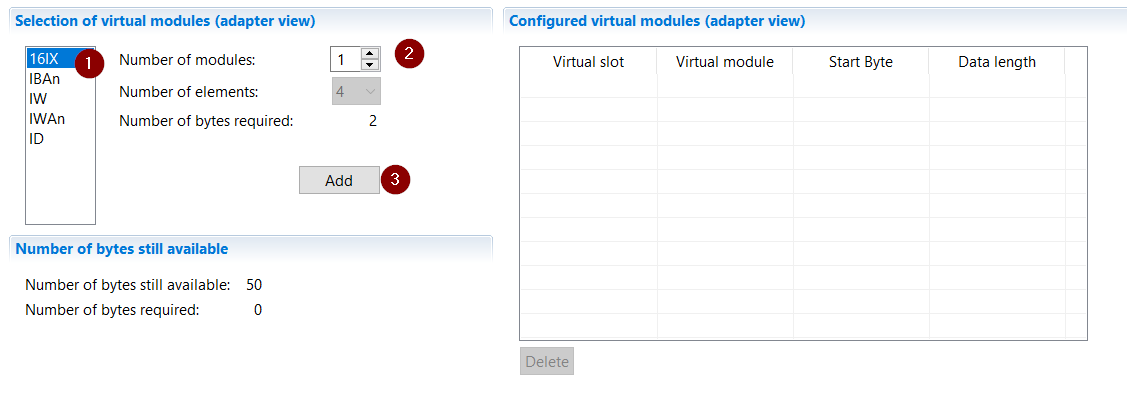
Virtual Module can be added under Ethernet/ip IDE.
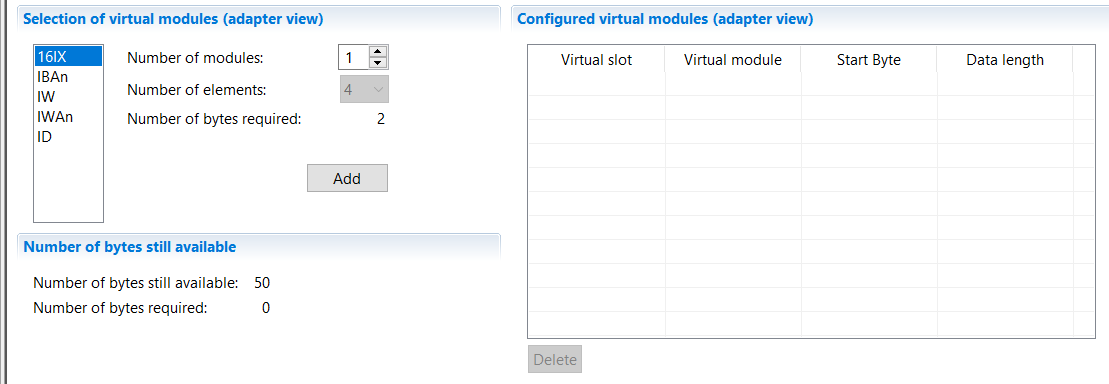
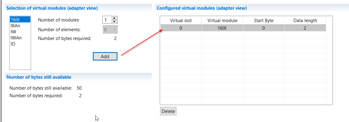
Add 16IX: Select 16IX and enter >Number of modules “1”.
16IX has been added to Virtual Slot 0!
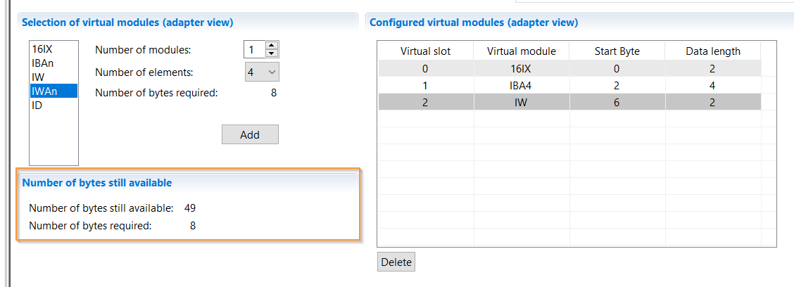
The same operation is used to insert Slot116An.
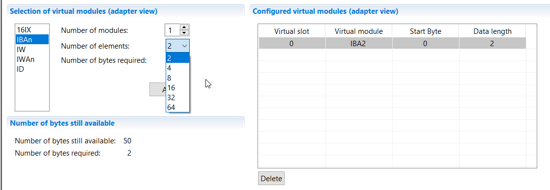
Set the Number Of elements to 4 and add it. 1 for Virtual Slot is Data Length 4 and Start Byte starts from 2.4 is the length of that array; since Virtual Slot is 16 Bit, the length of Data Length is 2, from 0 to 1.
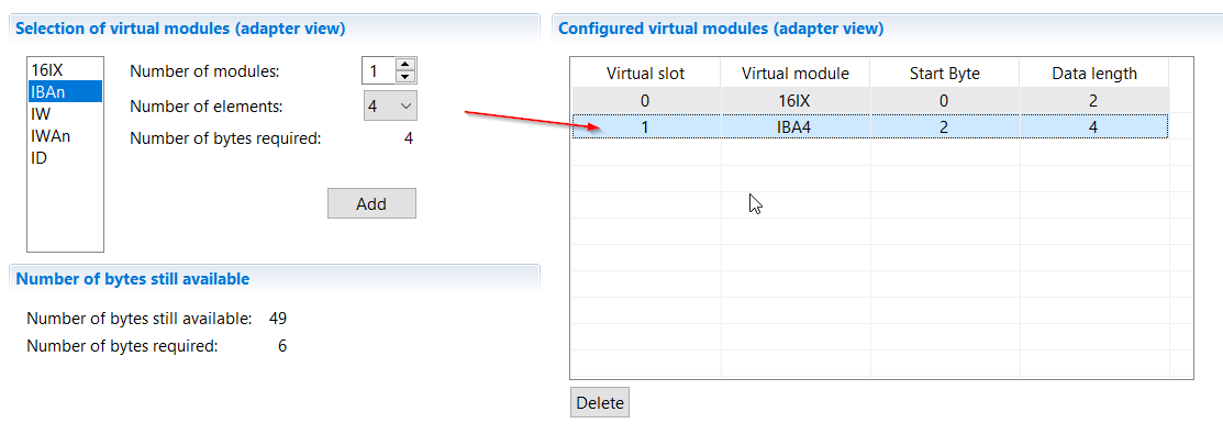
The number of bytes available and the number of bytes now occupied are also listed at the bottom.
Scanner Input
Add a Scanner Input Assembly with Add Scanner Input using the same operation as before.
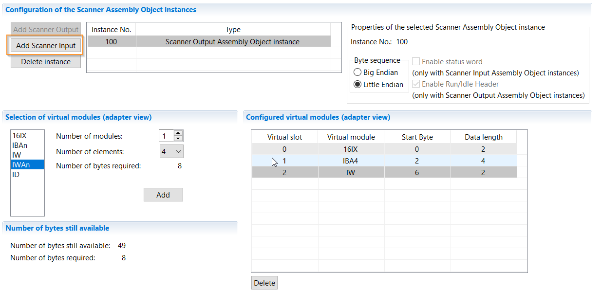
Use the same operation to add a Virtual Slot for the output.
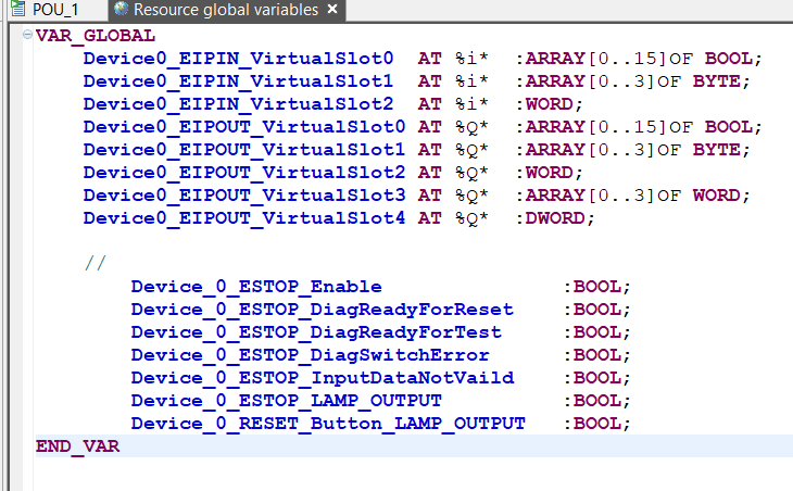
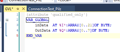
Global
Create Global variables with Resource global variables.
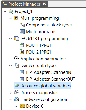
Add variables like this to match the Virtual Slot defined in the previous Step.
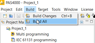
Build
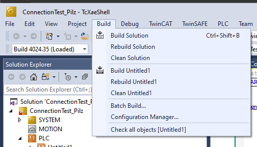
Compile your project with Build>Build All.
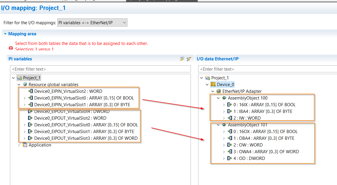
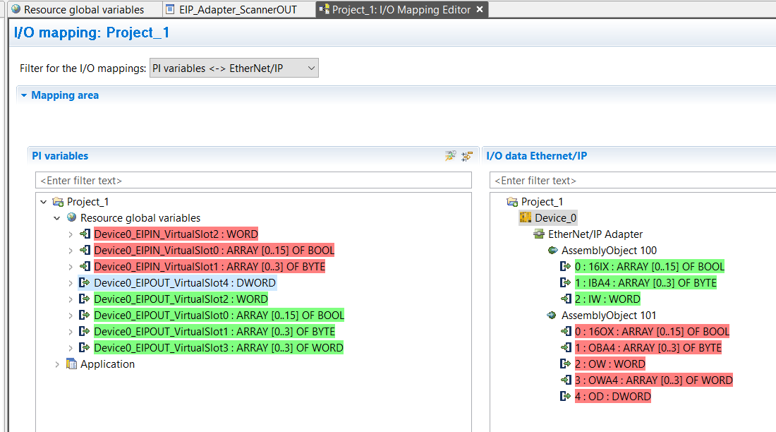
IO Mapping
Connect the Ethernet/ip variable to the User Program.
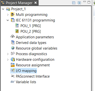
INPUT and OUTPUT are connected to Resource global variables.
Done!
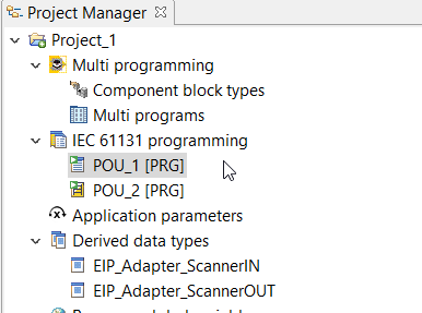
Program
POU2
Define VAR_EXTERNAL to access Global variables in POU2.
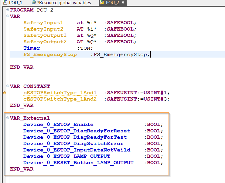
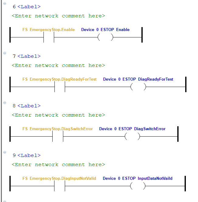
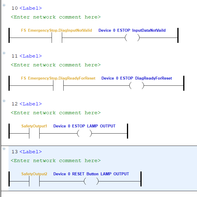
The FS_EmergencyStop status in the VAR_EXTERNAL variable is output to the VAR_EXTERNAL variable as is.
POU1
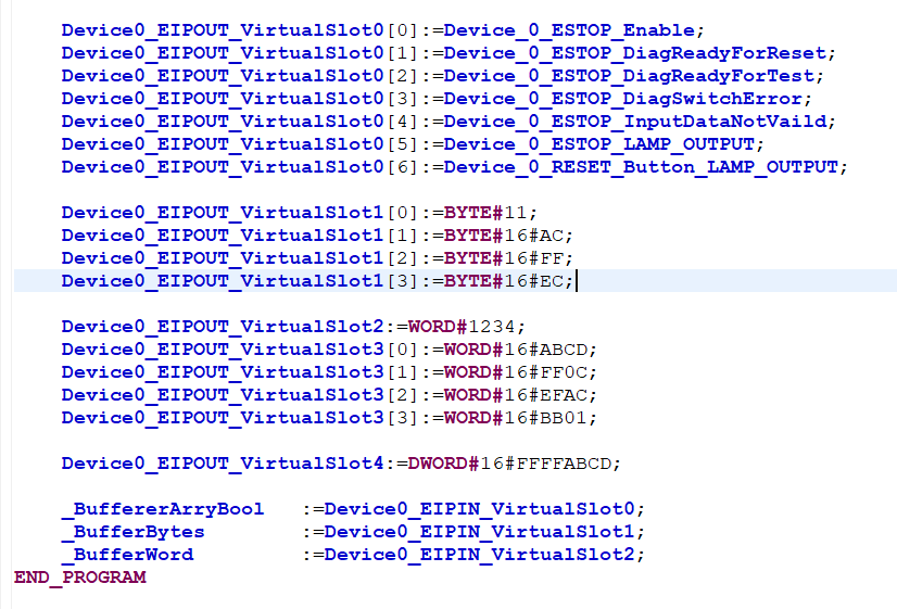
The next step is to create a program for transfer.
Define variables as you access Global variables in VAR_EXTERNAL as well.
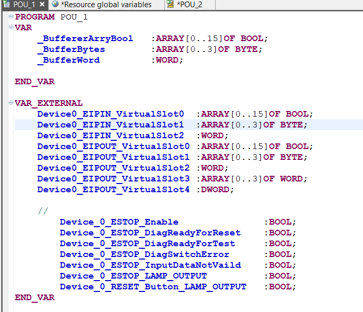
The program transfers the status of FS_EmergencyStop or sends Dummy data.
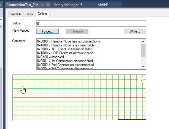
Status
Communication Error
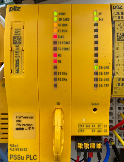
Normal Status with EIP Connection
https://youtube.com/shorts/RkULzk9kF9w
Implementation-1
In Implementation1, we will try to connect Pilz with Beckhoff IPC C6920.
Configure Ethernet/IP Scanner
Add Ethernet/IP Scanner
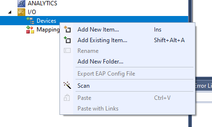
I/O>Devices>Add New Item.
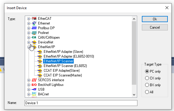
Select Ethernet/IP > Ethernet/IP Scanner > Ok to add.
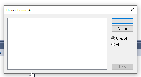
If Drive is not installed, Device Found At is empty, so close it with Ok for now.
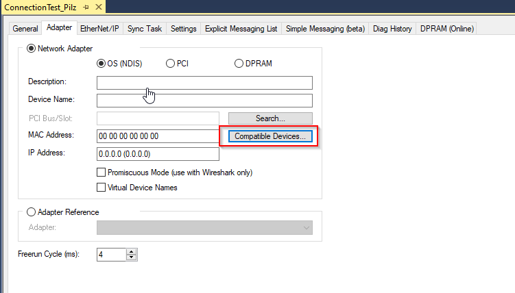
Install Driver
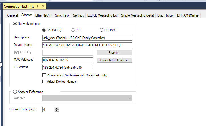
Real-Time Network adpaterをインストールします。AdapterのTabでCompatible Devicesをクリックします。
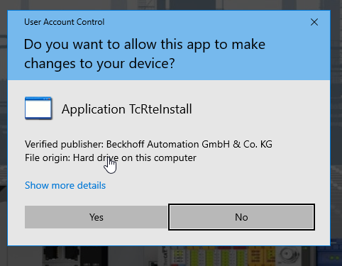
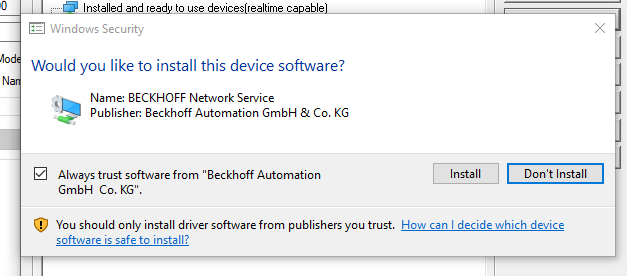
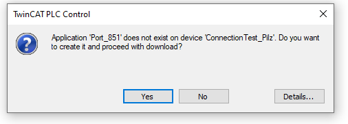
Proceed with Yes.
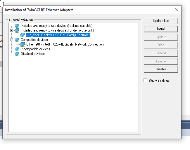
Lists the Netowork Adapter in the OS.
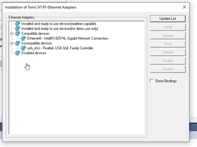
This time I will use a USB>LAN converter, so choose the appropriate Drive > Install and proceed.
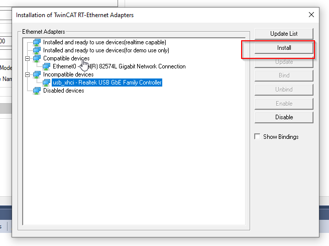
Proceed with Install.
Done!
Setup the Scanner Adapter
Sets the Network Adapter available for Search.
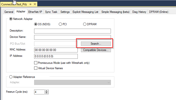
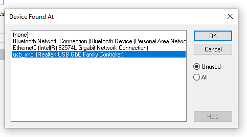
Done!
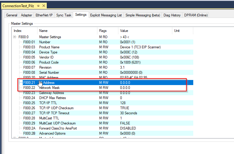
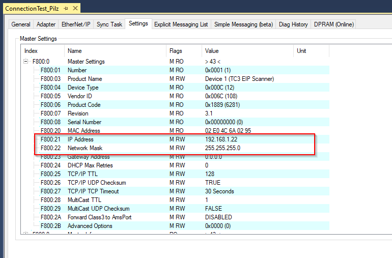
Configure IP
Configure the IP and Subnet of the Ethernet/ip Scanner from the Settings Tab.
Done!
Configure Task
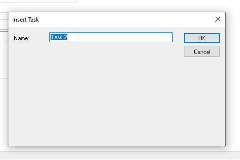
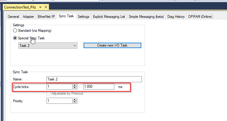
Create a new Task with Create New I/O Task from Sync Task.
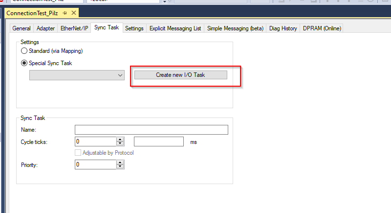
Enter a task name and click OK.
Cycle ticks should be set according to the actual application.
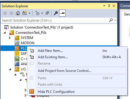
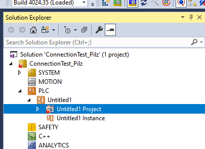
Add PLC
Select PLC>right click>Add new Item.
Select Standard PLC Project > Add to add a new PLC.
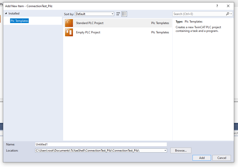
Done!
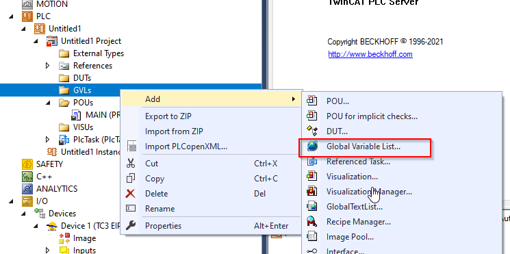
ADD GVL
Define a Process IO to connect to the Pilz CPU, GVLs>Add>Global Variable List.
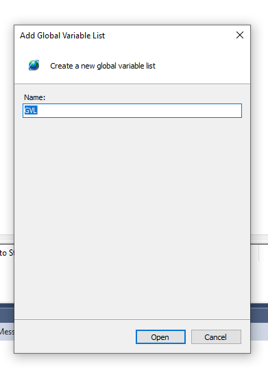
Enter the name of the GVL and Open.
Done!
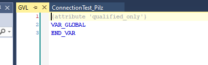
Then define Process IO.
Main Program
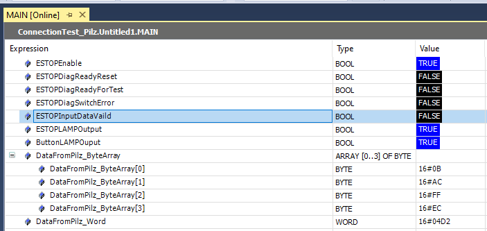
The program retrieves the ESTOP state from the data received from Pilz and returns the Dummy data to Pilz.
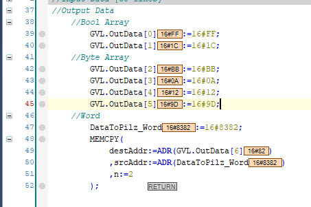
| PROGRAM MAIN VAR ESTOPEnable:BOOL; ESTOPDiagReadyReset:BOOL; ESTOPDiagReadyForTest:BOOL; ESTOPDiagSwitchError:BOOL; ESTOPInputDataVaild :BOOL; ESTOPLAMPOutput :BOOL; ButtonLAMPOuput :BOOL; DataFromPilz_ByteArray :ARRAY[0..3] OF BYTE; DataFromPilz_Word :WORD; DataFromPilz_WordArray :ARRAY[0..3] OF WORD; DataFromPilz_DWord :DWORD; DataToPilz_Word :WORD; END_VAR //Input Data //Bool Array ESTOPEnable :=GVL.inData[2].0; ESTOPDiagReadyReset :=GVL.inData[2].1; ESTOPDiagReadyForTest :=GVL.inData[2].2; ESTOPDiagSwitchError :=GVL.inData[2].3; ESTOPInputDataVaild :=GVL.inData[2].4; ESTOPLAMPOutput :=GVL.inData[2].5; ButtonLAMPOuput :=GVL.inData[2].6; //Bye Array MEMMOVE( destAddr:=ADR(DataFromPilz_ByteArray) ,srcAddr:=ADR(GVL.inData[4]) ,n:=4 ); //Word MEMMOVE( destAddr:=ADR(DataFromPilz_Word) ,srcAddr:=ADR(GVL.inData[8]) ,n:=2 ); //Word Array MEMMOVE( destAddr:=ADR(DataFromPilz_WordArray) ,srcAddr:=ADR(GVL.inData[10]) ,n:=8 ); //DWord MEMMOVE( destAddr:=ADR(DataFromPilz_DWord) ,srcAddr:=ADR(GVL.inData[18]) ,n:=4 ); //Output Data //Bool Array GVL.OutData[0]:=16#FF; GVL.OutData[1]:=16#1C; //Byte Array GVL.OutData[2]:=16#BB; GVL.OutData[3]:=16#0A; GVL.OutData[4]:=16#12; GVL.OutData[5]:=16#9D; //Word DataToPilz_Word:=16#8382; MEMCPY( destAddr:=ADR(GVL.OutData[6]) ,srcAddr:=ADR(DataToPilz_Word) ,n:=2 ); |
Build
Build>Build Solution to compile the Project.
Configure With EDS File
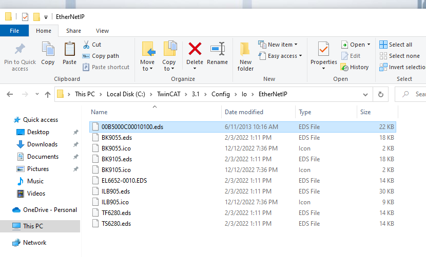
Install the EDS File
First, we will show you how to build the Ethernet/ip Network from the EDS File. Put the EDS File downloaded earlier into TwinCAT/3.1/Config/io/EthernetIP.
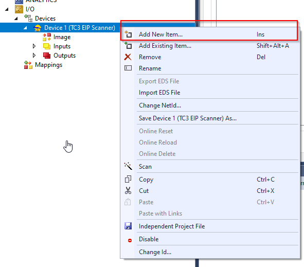
Add Adapter
Select Scanner>Right click>Add New Item.
Select Pilz PSS4000 and Ok.
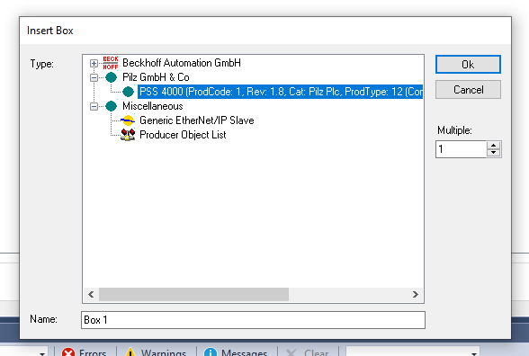
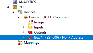
Pilz CPU Ethernet/ip Adapter has been added.
Change IP
Right click on the Adapter>Change IP Address to change the IP of the Pilz Adapter.
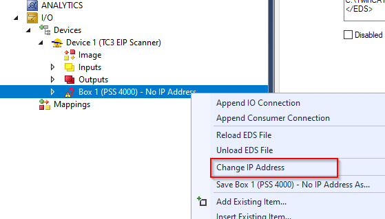
Set it up according to the Pilz actual device.
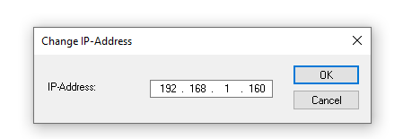
Done!The ? Mark has also disappeared.
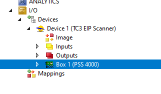
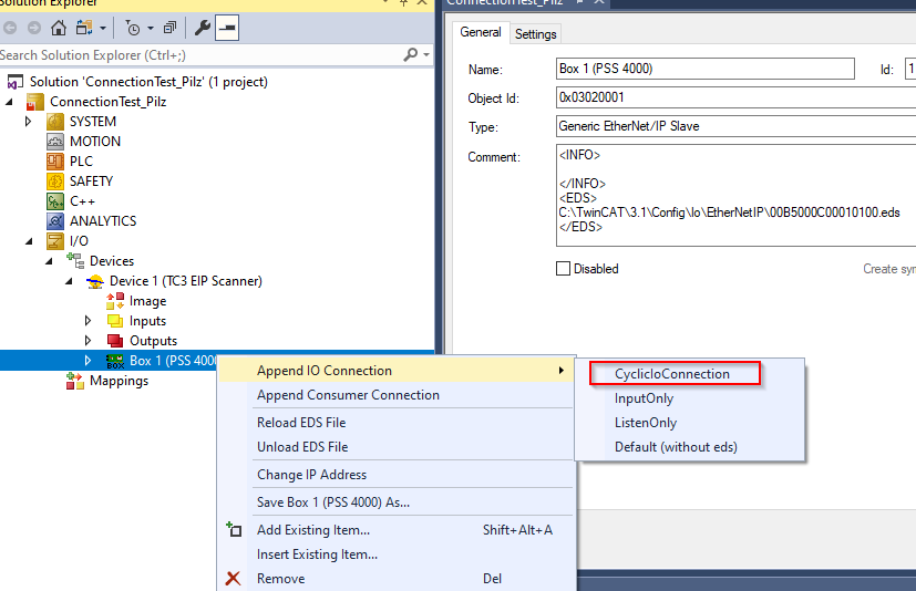
Add IO
Add Cyclic IO Connection data to Pilz Adapter by selecting Box>Right click>Append IO Connection>CyclicIoConnection.
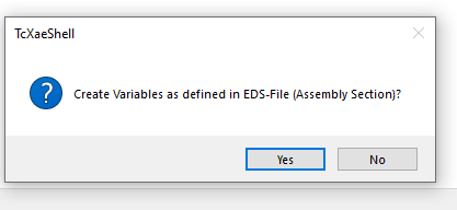
Press Yes.
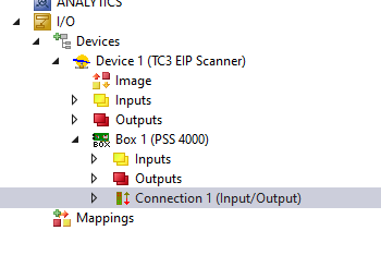
Connection has been added.
Configure the Connections
Double-click on the Connection and configure detailed settings for the Connection.
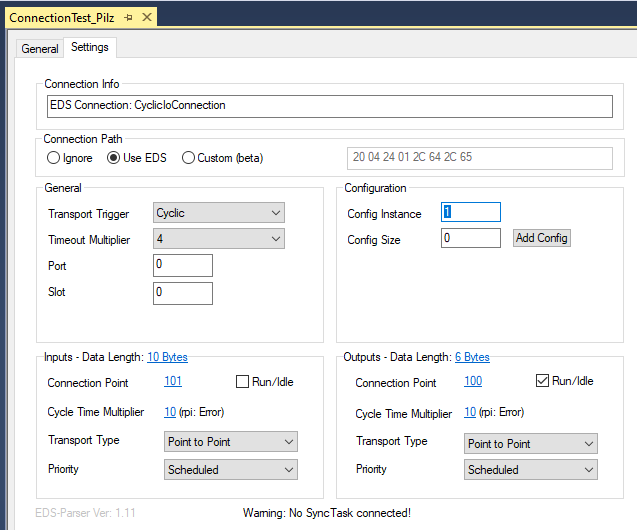
Input Length
IThe default length of input Data is 10 Bytes.
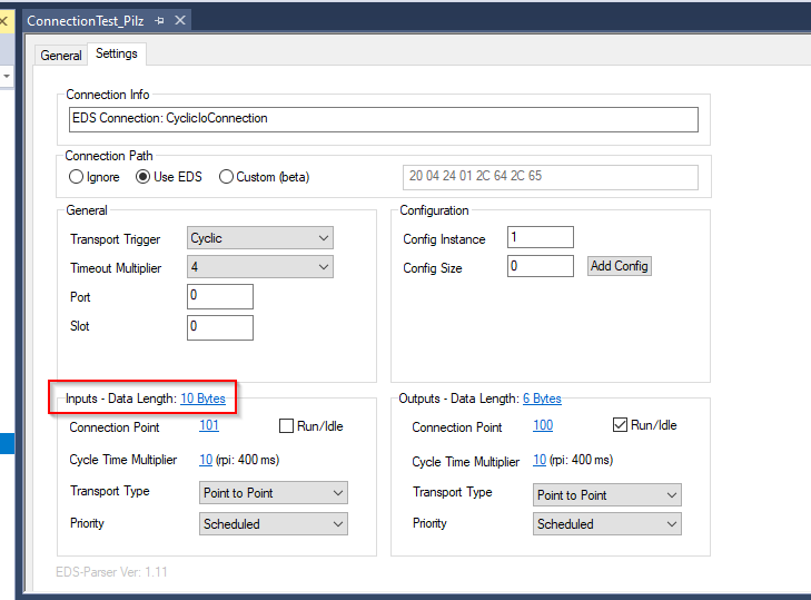
In fact, the number of data in the ScannerInput Assembly should be matched to the number of data in the ScannerInput Assembly.
Output Length
The default length of Output Data is 6 Bytes.
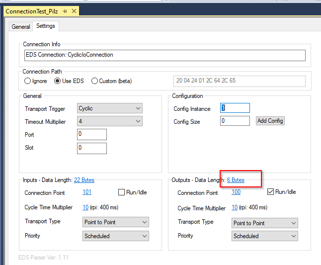
In fact, the number of data in the ScannerOutput Assembly should be matched to the number of data in the ScannerOutput Assembly.
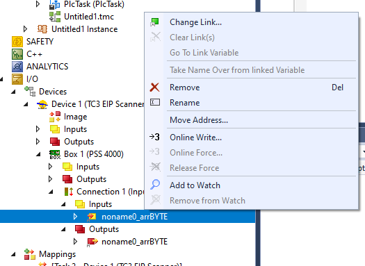
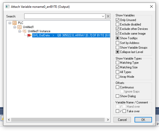
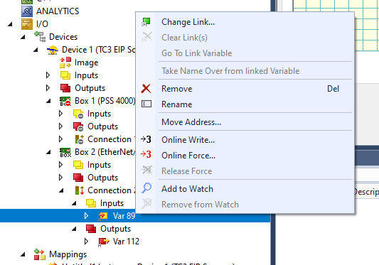
Link INPUT
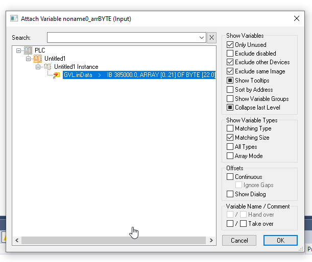
Link to Process Input and User Program variables. Right click>Change Link. Right-click>Change Link….
Let’s link with the variable we just defined in GVL.
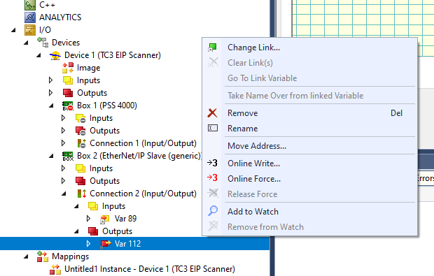
Link Output
Link to Process Output and User Program variables. Right click>Change Link. Right-click>Change Link….
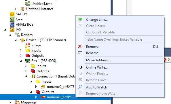
Let’s link with the variable we just defined in GVL.
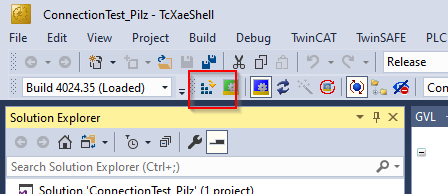
Download
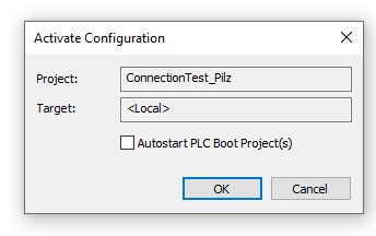
Download the Project by pressing the Activate Configuration Button.
OK to Download Configuration.
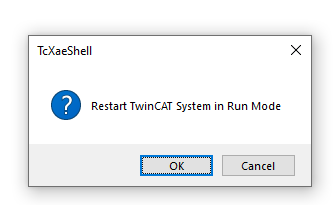
Switch Runtime to Run Mode.
Start
Login to the TwinCAT Runtime.
Proceed with Yes.
Result
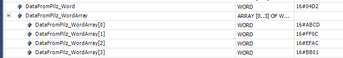
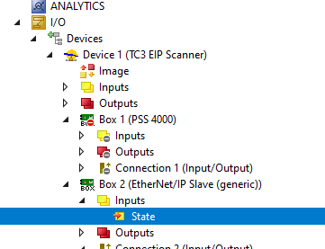
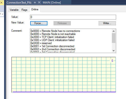
First, check the connection status from the State variable.
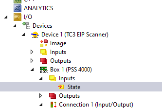
0=No error, the connection is successful .
Pilz You also received the data from the CPU.
Output Data should also reach the Pilz CPU!
Configure without EDS File
Next we will build an Ethernet/ip Network without EDS File, using the Generic method from Twincat.
Disable
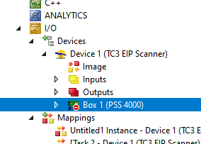
First, disable the Adapter that has just been set up.
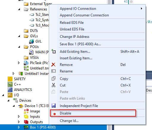
Done!
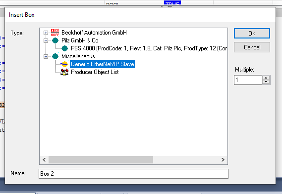
Add Adpter
Now select Generic EtherNet/IP Slave >Ok.
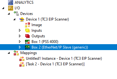
Generic EtherNet/IP Slave has been added.
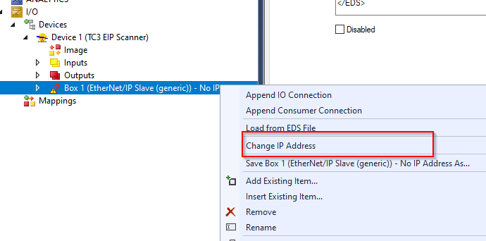
Change IP
Right-click on the box > Change IP Address.
Add Connections
Right click on Generic EtherNet/IP Slave>Append IO Connection>Default (Without EDS) to proceed.
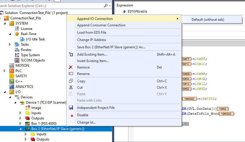
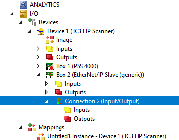
Connection has been added.
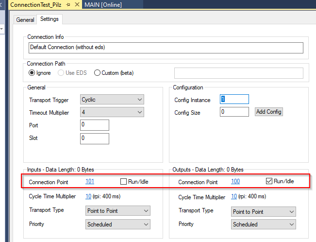
Configure Connections
As before, connection information must be set.
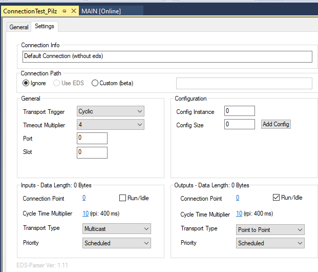
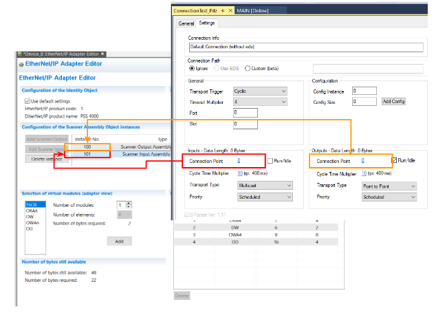
Twincat’s Connection Port is the Instance number to connect to.
The Scanner Input Assembly is the Connection Port (101) of Inputs and the Scanner Output Assembly is the Output Port (100).
Done!
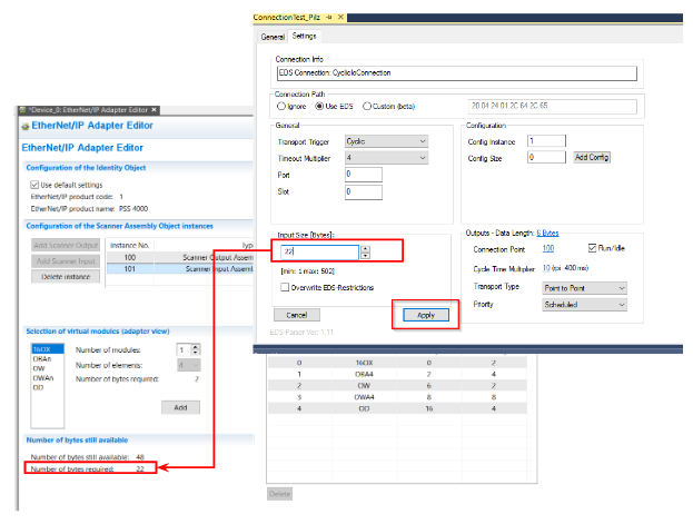
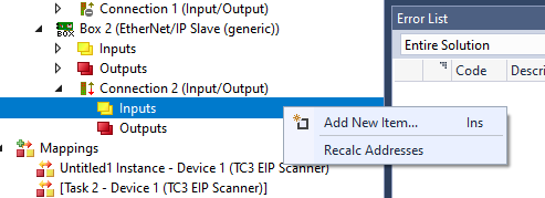
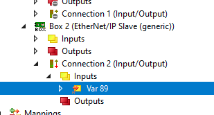
Add Input Data
Next we add Input Data, we configured 8 Bytes in the Pilz CPU.
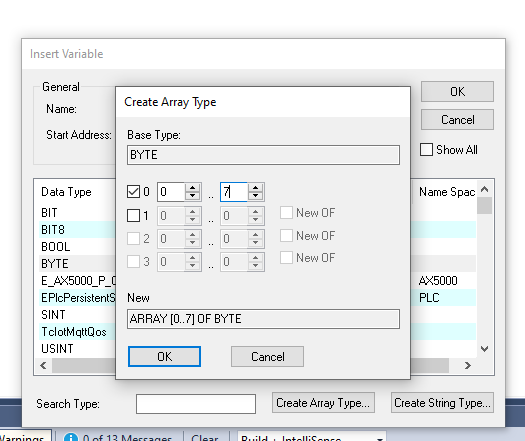
Click Create Array Type.
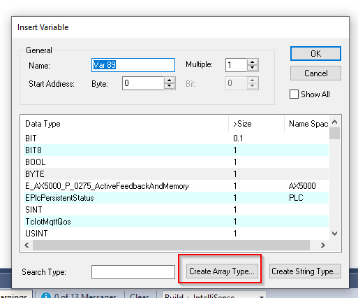
Create an array and complete with Ok.
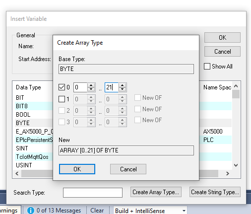
Done!
Add Output Data
The same operation is used for Outputs to add a variable: Go to Outputs>Right click>Add New Item.
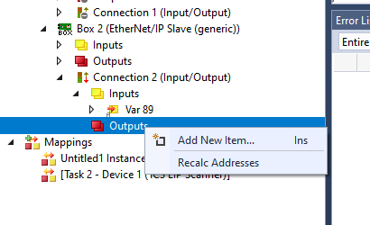
Creates an array of 8Bytes in length.
Done!
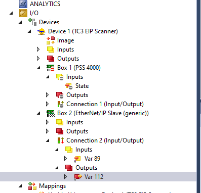
Link Input
Right-click on the Inputs variable>Change Link… to link the variable to the User Program variable.
Link Output
Right-click on the Outputs variable>Change Link. to link to the User Program variable.
Result
Check the connection results from the State variable.
If 0, there is no connection problem.
You can also receive the data from the Pilz CPU via Ethernet/IP.
Output Data should also reach the Pilz CPU!
Implementation-2
In Implementation2 ,we will try to connect with Pilz and RJ71EIP91.
Mels
Add New Project
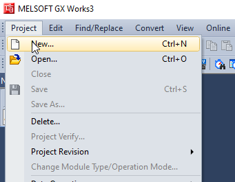
Start GXWorks3 and add a new project by going to Project>New.
In this article, we will use R00, with RCPU as the Series, R00 as the Type, and ST as the Program Language.
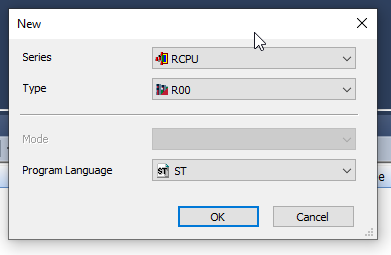
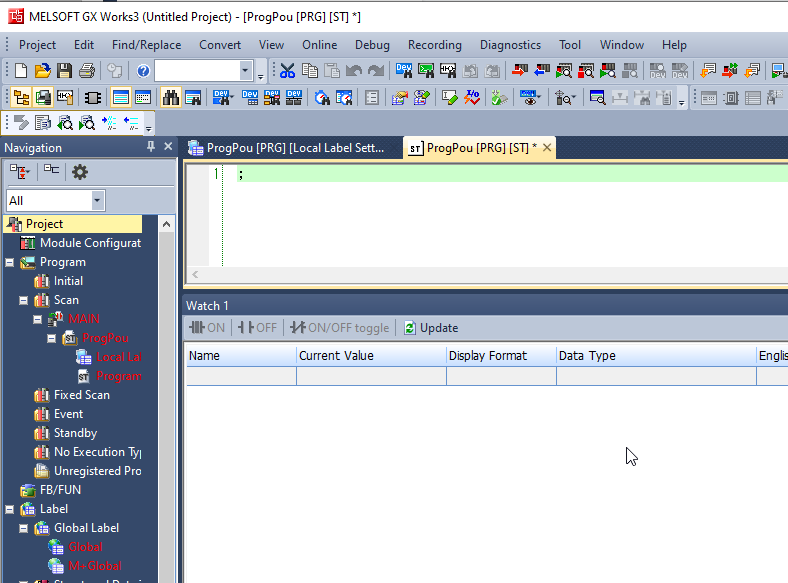
A new project has been created.
Insert RJ71EIP91 Module
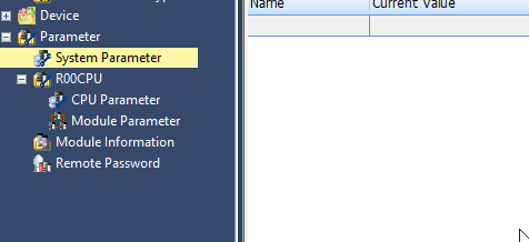
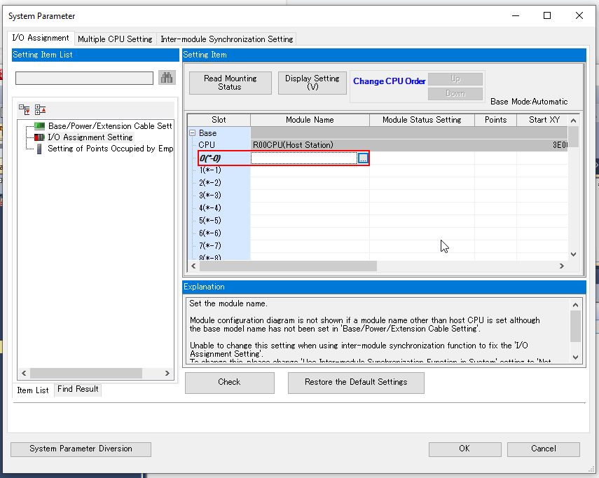
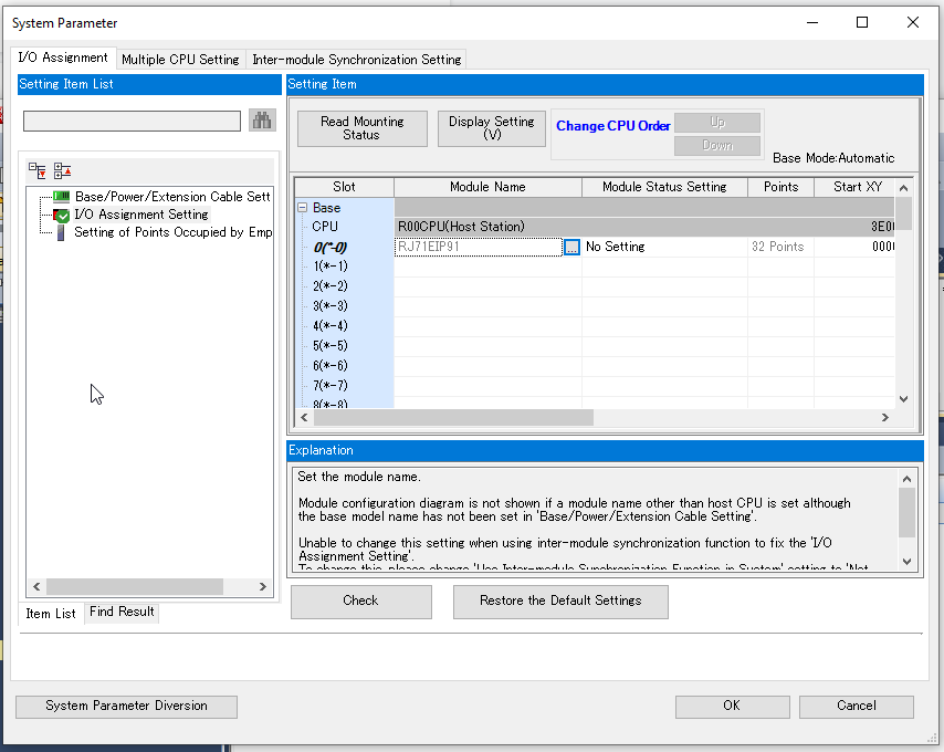
Next install the RJ71EIP91 module and click on Parameter>System Parameter.
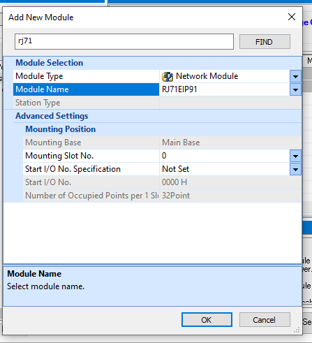
Click the “To Slot0…” button.
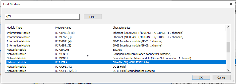
Search for Rj71.
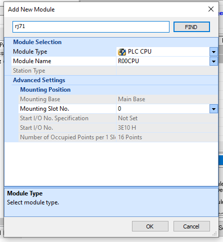
Select RJ71EIP91 >Ok.
Insert RJ71EIP91 into Project with OK again.
Done!
Configure IP Address
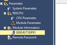
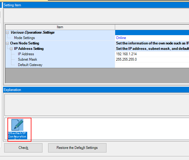
Set the IP address of the RJ71EIP91; click Module Information>RJ71EIP91.
Open Basic Setting.
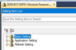
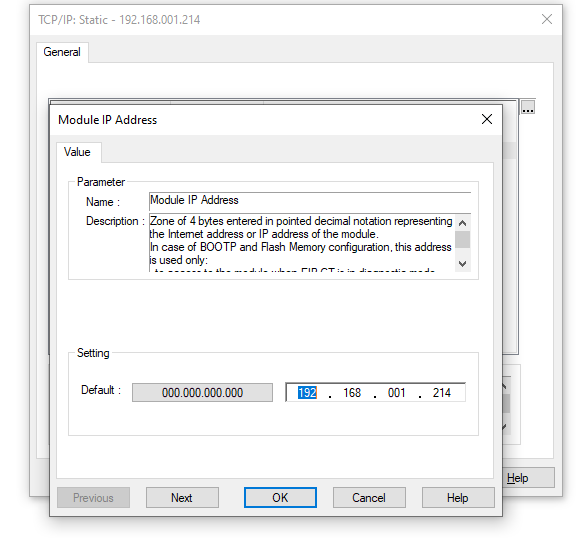
Double-click on the red frame in IP Address Setting.
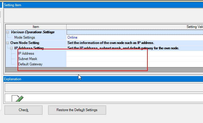
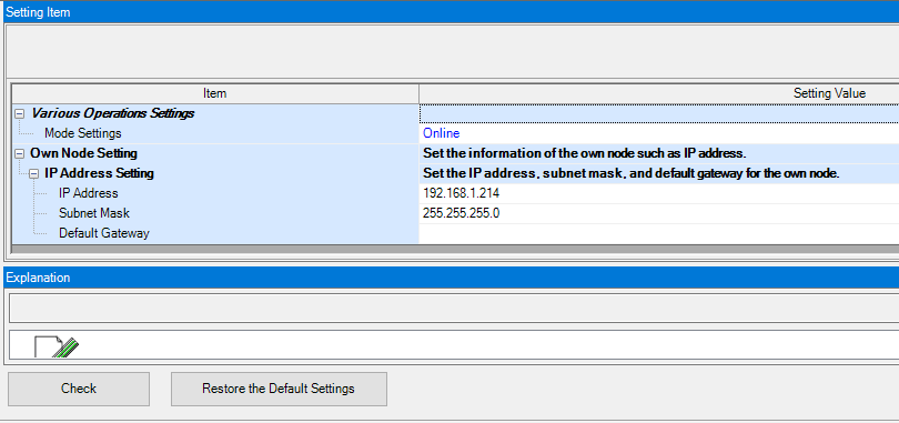
Please set IP Address, Subnet Mask, and Default Gateway according to the application.
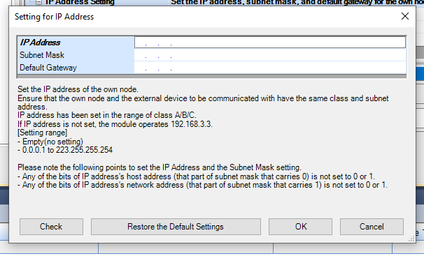
This time we will use 192.168.1.241/24.
Basic Program
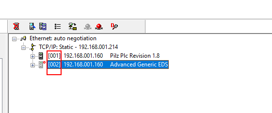
Here is the basic program: if you change FlagSend.uiConnectionNo and FlagReceive.UiConnectionNo to 2, you will have access to the data of Connection2 .
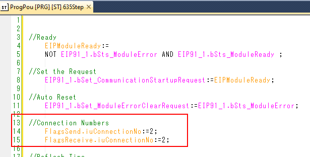
The connection number is displayed next to the tool as [001],[002].
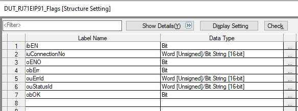
DUT_RJ71EIP91_Flags
These are Input/Output parameters when calling Function Block of Class 1 Set/ClassGet. It is troublesome to define them one by one, so they are declared together in a structure.
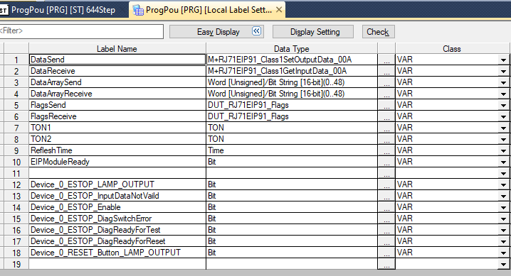
MAIN
This is the Main program. Now it is called a Function Block once every 200ms.
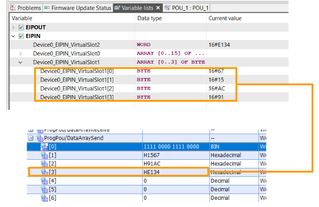
| //Ready EIPModuleReady:= NOT EIP91_1.bSts_ModuleError AND EIP91_1.bSts_ModuleReady ; //Set the Request EIP91_1.bSet_CommunicationStartupRequest:=EIPModuleReady; //Auto Reset EIP91_1.bSet_ModuleErrorClearRequest:=EIP91_1.bSts_ModuleError; //Connection Numbers FlagsSend.iuConnectionNo:=1; FlagsReceive.iuConnectionNo:=1; //Reflesh Time RefleshTime:=T#200ms; //Send Reflesh TON1( IN:= NOT TON1.Q AND EIPModuleReady AND NOT EIP91_1.bnSts_Class1Error_Connection_D[2] ,PT:= RefleshTime ,Q=>FlagsSend.ibEN ); //Receive Reflesh TON2( IN:= NOT TON2.Q AND EIPModuleReady AND NOT EIP91_1.bnSts_Class1Error_Connection_D[2] ,PT:= RefleshTime ,Q=>FlagsReceive.ibEN ); //Send DataArraySend[0]:=16#F0F0; DataArraySend[1]:=16#1567; DataArraySend[2]:=16#91AC; DataArraySend[3]:=16#E134; DataSend( i_bEN:= FlagsSend.ibEN ,i_stModule:= EIP91_1 ,i_uConnectionNo:= FlagsSend.iuConnectionNo ,i_uOutputData:= DataArraySend[0] ,o_bENO=> FlagsSend.oENO ,o_bOK=> FlagsSend.obOK ,o_bErr=> FlagsSend.obErr ,o_uErrId=> FlagsSend.ouErrId ,o_uStatusId=>FlagsSend.ouErrId ); //Receive DataReceive( i_bEN:= FlagsReceive.ibEN ,i_stModule:= EIP91_1 ,i_uConnectionNo:= FlagsReceive.iuConnectionNo ,o_bENO=> FlagsReceive.oENO ,o_bOK=> FlagsReceive.obOK ,o_bErr=> FlagsReceive.obErr ,o_uErrId=> FlagsReceive.ouErrId ,o_uStatusId=> FlagsReceive.ouStatusId ,o_uInputData=> DataArrayReceive[0] ); Device_0_ESTOP_Enable:=DataArrayReceive[1].0; Device_0_ESTOP_DiagReadyForReset:=DataArrayReceive[1].1; Device_0_ESTOP_DiagReadyForTest:=DataArrayReceive[1].2; Device_0_ESTOP_DiagSwitchError:=DataArrayReceive[1].3; Device_0_ESTOP_InputDataNotVaild:=DataArrayReceive[1].4; Device_0_ESTOP_LAMP_OUTPUT:=DataArrayReceive[1].5; Device_0_RESET_Button_LAMP_OUTPUT:=DataArrayReceive[1].6; ; |
Startup Configuration tools
Return to GXWORKS3 and start the Etherent/IP Configuration Tool.
Just a second..
Configuration Tool has been started.
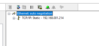
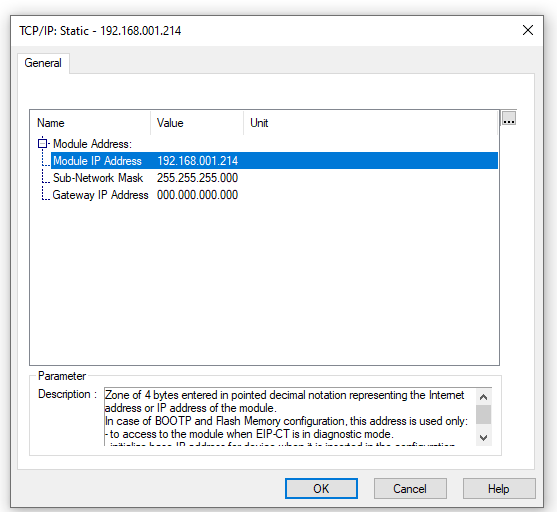
Configure RJ71EIP91 IP
First, configure the RJ71EIP91 unit.
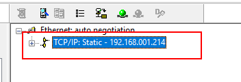
IP address should be set according to Project.
Configure by EDS
In the first implementation, we will install the EDS File downloaded from Pilz HP and build an Ethernet/IP Network.
Install the EDS File
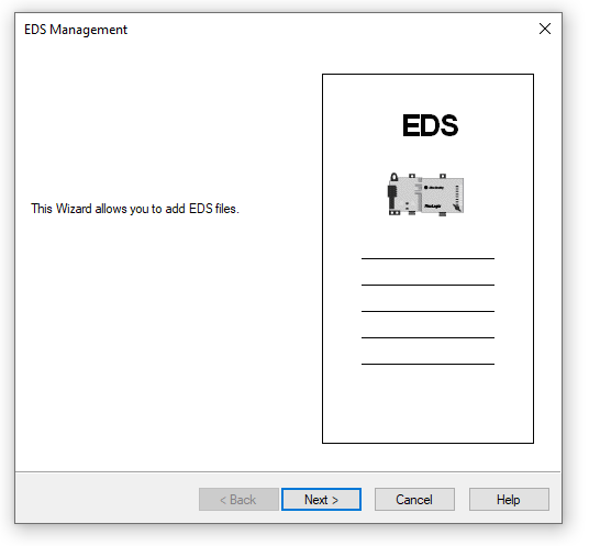
Install EDS File with Add.
Proceed with Next>.
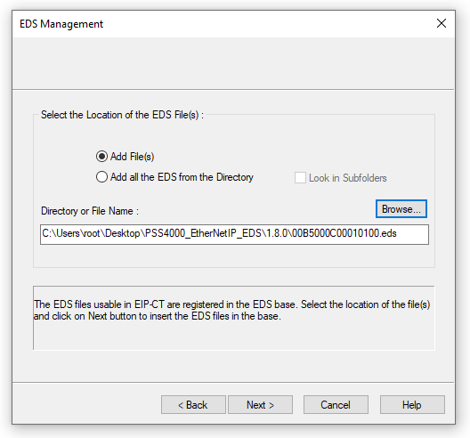
Set the EDS File Directory and proceed with Next> to install and you are good to go.
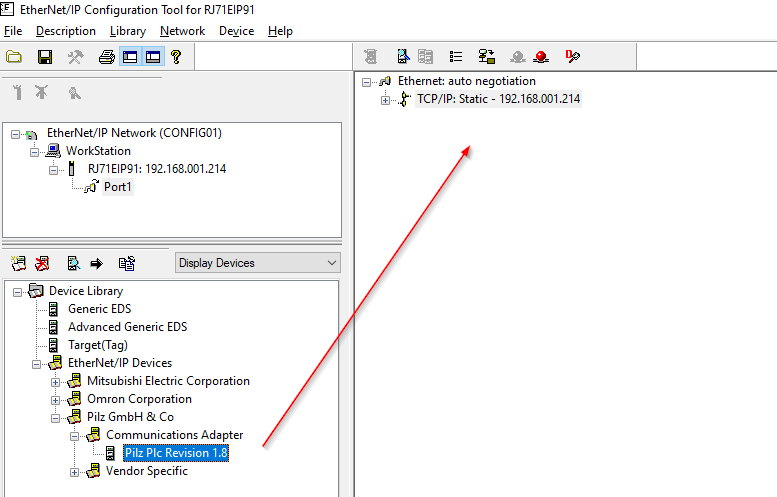
Insert the Pilz PLC Adapter
Select Ethernet/IP Devices>Pilz GmbH & Co>Communications Adapter>Pilz PLC Reveision 1.8 and add it to your Ethernet/IP network.
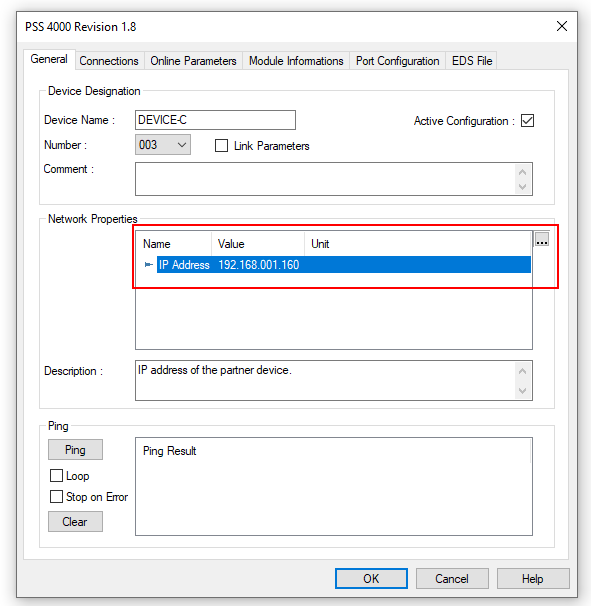
Ip address
The IP address should match the actual device.
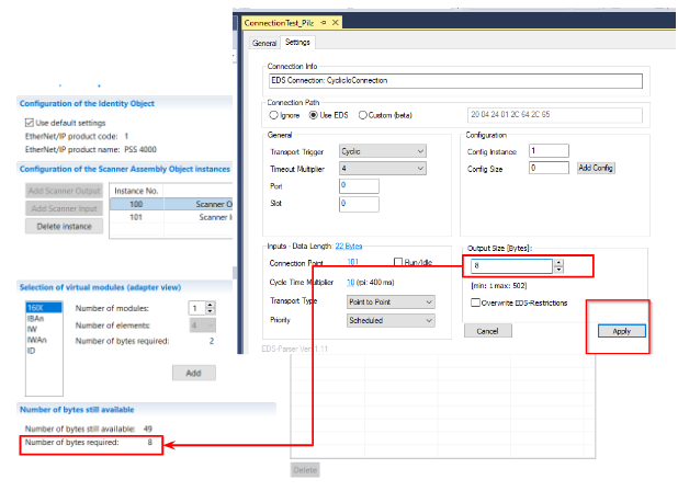
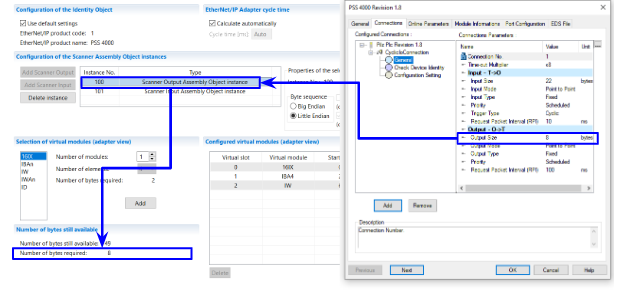
Configure the Input Data Size
Next, from the Connections Tab, set up detailed information about the connection.
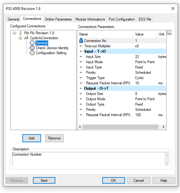
The Input Size is 22 Bytes, and the 22 Bytes are for the Scanner Input Assembly Object Instance on the Pilz side.
Configure the Output Data Size
The Output Size is 8Bytes, and the 8 Bytes are for the Scanner Output Assembly Object Instance on the Pilz side.
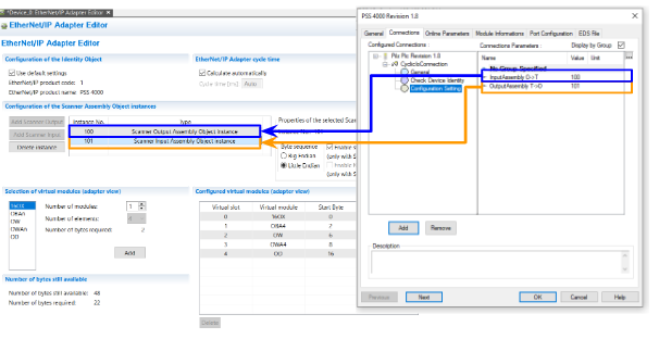
Configure the Instance Number
The next step is to set the Instance number.
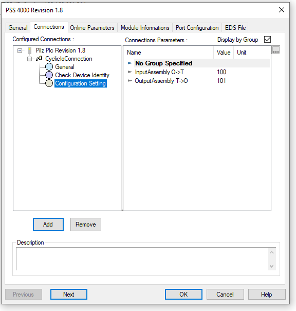
The Input Instance O->T is 100,reference to the Pilz’s Scanner Output Assembly Object Instance. And Also the Output Instance T->O 101 is reference to the Pilz’s Scanner Input Assembly Object Instance.
Download
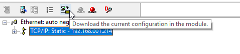
Connect the Tools with Modules via Online Command.
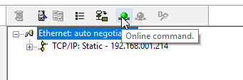
Press “Download the current configuration in the module” to download the configuration to the module.
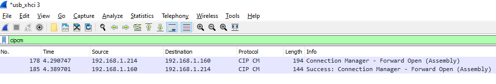
Result
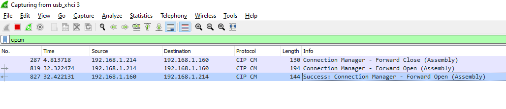
Okay, the CIP CM Package is here, and Pilz has sent a Success reply to Forward Open!
Configure by Generic EDS
The next step is to build an Ethernet/IP Network from a Generic EDS File without an EDS File.
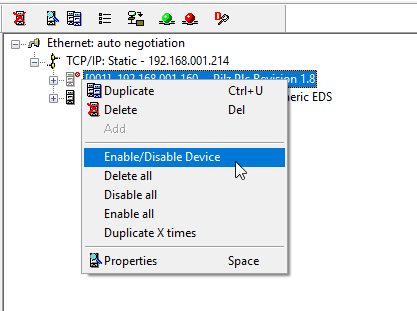
Disable
Right-click on the Connection you just implemented>Enable/Disable Device to disable the Connection.
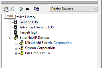
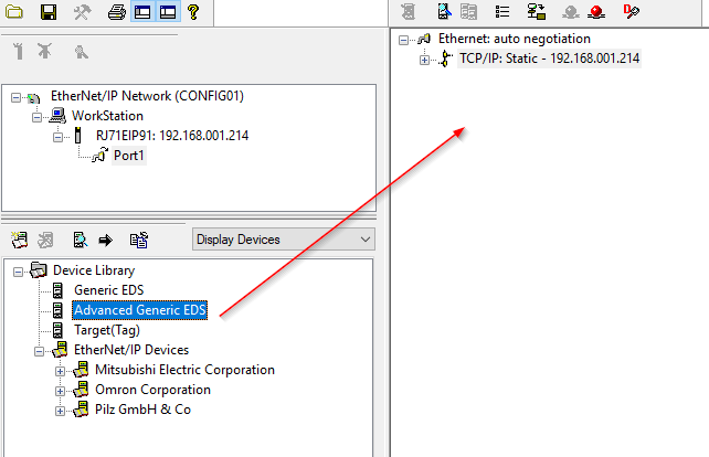
Install the Generic EDS
Select Device Library>Advanced Generic EDS and add to Ethernet/IP Network.
Ip address
The Ip address should also match the actual Pilz device.
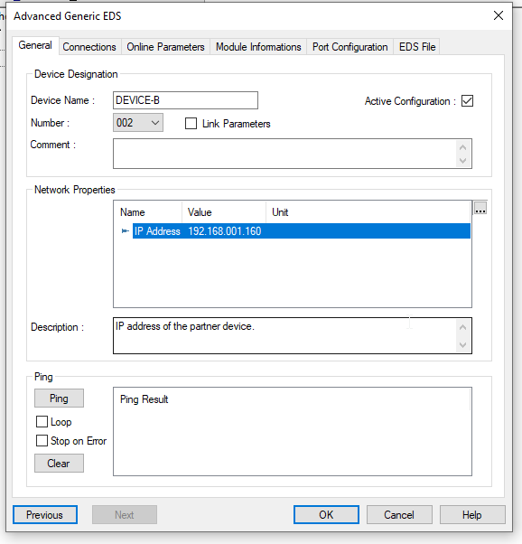
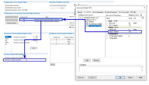
From the Connections Tab, you can configure detailed settings for the connection.
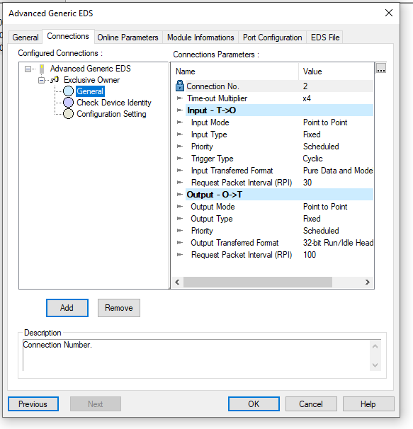
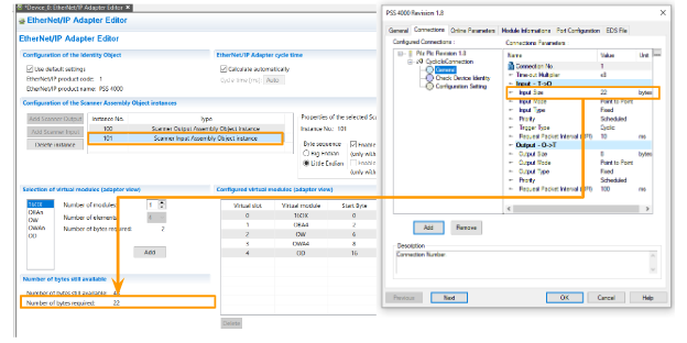
Configure the Input Data Size/Instance
Input instance 101 corresponds to the Scanner Input Assembly Object Interface from Pilz’s perspective.
Output Instance 100 corresponds to the Scanner Output Assembly Object Interface from Pilz.
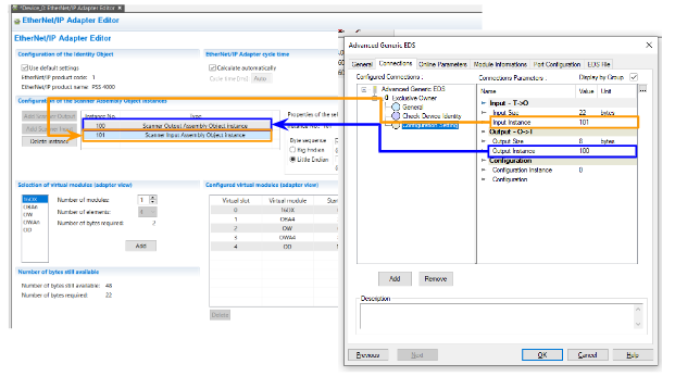
Configure the Output Data Size/Instance
Input Size 22 Bytes is 101 for Pilz’s Scanner Input Assembly Object Interface, whose Instance101 is 22 Bytes.
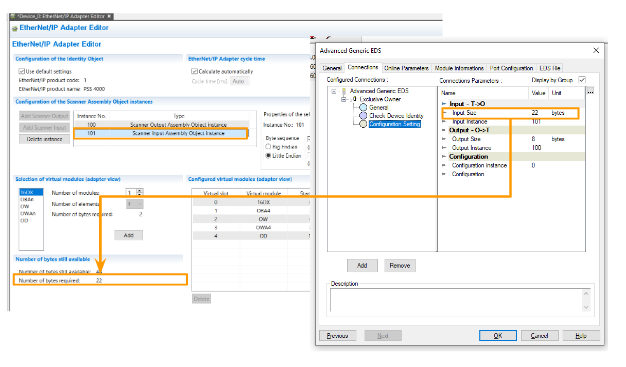
Output Size 22 Bytes is 100 of Pilz’s Scanner Output Assembly Object Interface, and its Instance 100 is 8 Bytes.
Download
Connect the tools and Module via Online command.
Press “Download the current configuration in the module” to download the configuration to the module.
Result
Okay, the CIP CM Package is here, and Pilz has sent a Success reply to Forward Open!
You also got the data right from Pilz!
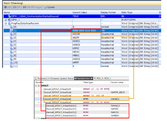
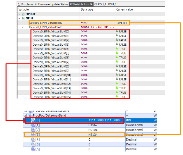
The Mitsubishi side sent the data properly to Pilz as well.