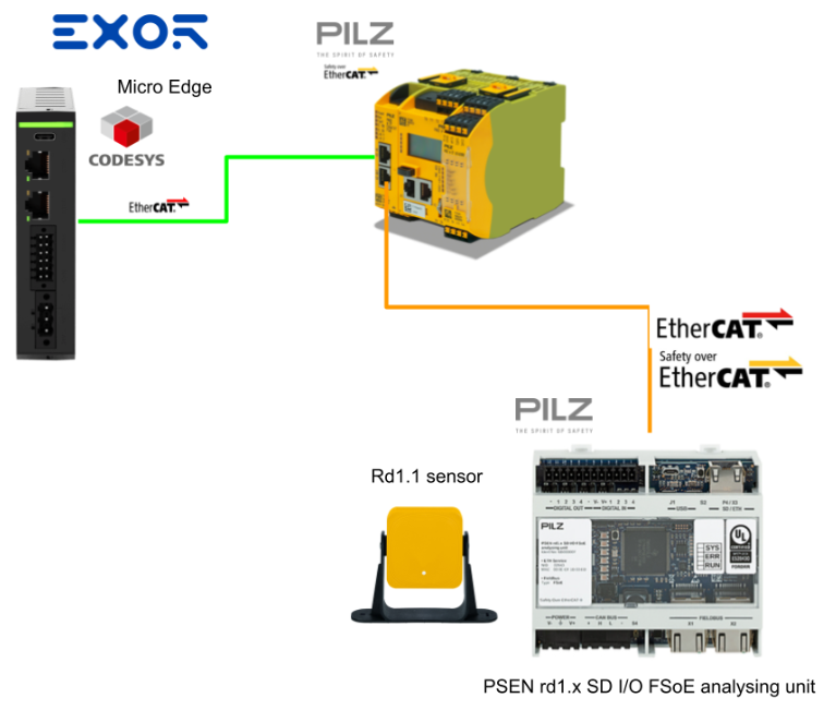
In this article, we will use Codesys with MicroEdge Basic from EXOR to set up an EtherCAT Master and an FSOE network with EtherCAT FSoE module from Pilz.
FSoE Slave is a PSEN rd1.x SD I/O FSoE analysing unit Safety ledger from Pilz.
Let’s Enjoy FA.
Reference Link
PSEN rd1.x?
The PSEN rd1.2 system can be integrated with the machine’s control system. When performing a safety function or detecting a fault, the PSEN rd1.2 system changes the safety output to inactive. The advantage is that the control system can put the area into a safe state or prevent the machine from restarting, since it maintains the inactive state.
In the absence of other control systems, the PSEN rd1.2 system can be connected to devices that control power and machine startup, but does not perform normal machine control functions.
Functions
Analysing unit performs include the following functions:
- Collects information from all sensors via the CAN bus.
- Compares the detected motion position with the set value and deactivates the selected safety outputs if at least one sensor detects motion in the detection field.
- Deactivates all safety outputs if a failure is detected in either the sensor or the analysis unit.
- For all configuration and diagnostic functions can be viewed and changed via the PSEN rd1 Configurator.
- Different configurations can be switched dynamically.
- Can communicate with the safety PLC via a safety fieldbus connection (if available).
- Can communicate and exchange data via MODBUS protocol (if available).
- Can backup to microSD card (if available) and restore system configuration and passwords from microSD card.
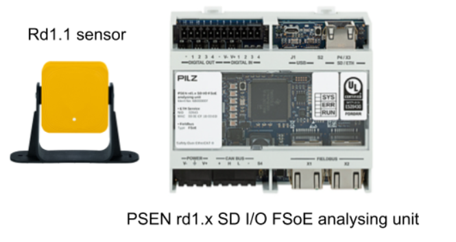
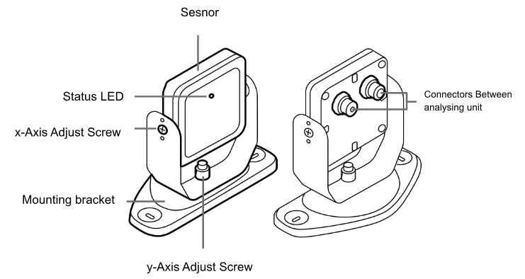
Main components
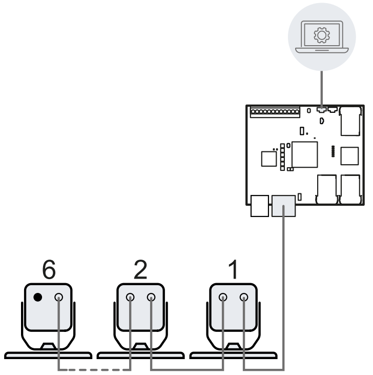
PSEN rd1.2 System Analysing unit with up to 6 sensors. psen rd1 CoConfigurator allows configuration and checking of system operation.
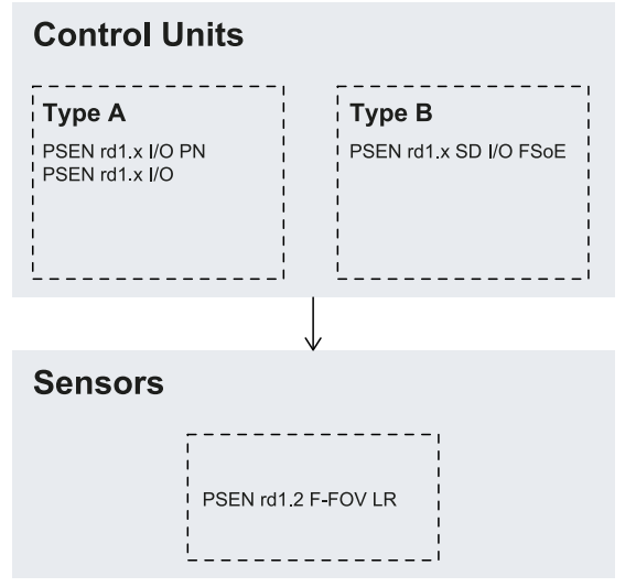
Compatibility
The following is a list of compatible models and interchangeability of Analysing unit and sensor types.
Sensor communication
The sensor communicates with the analyzer unit via the CAN bus using a diagnostic mechanism compliant with the EN 50325-5 standard to guarantee SIL 2 and PL d.
To function properly, each sensor must be assigned an identification number (Node ID). Sensors on the same bus must have different Node IDs. By default, sensors do not have a pre-assigned Node ID.
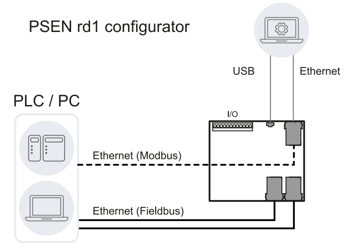
Communication architecture
Depending on the model type, the configuration between the Analysing unit, PLC and PC can be implemented as follows;
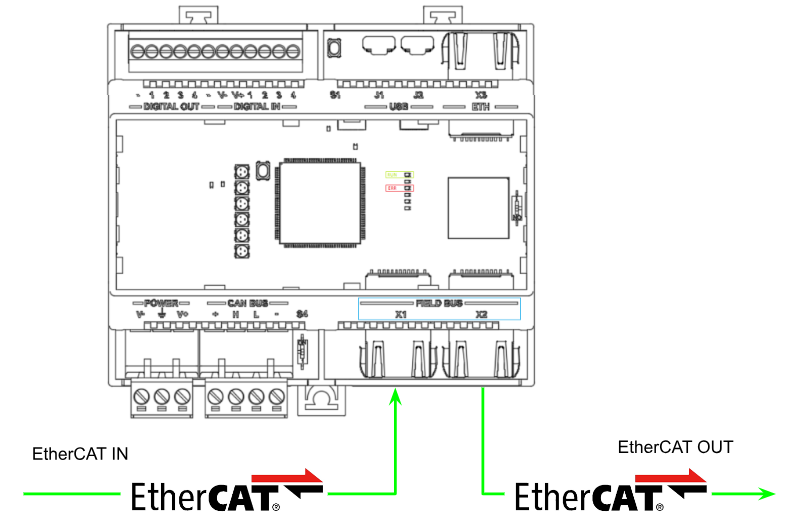
Layout
This is the Layout of the system.
EtherCAT
Since FSoE is used in this article, X1 is EtherCAT IN Data and X2 is EtherCAT Out Data.
Cyclical data transmission
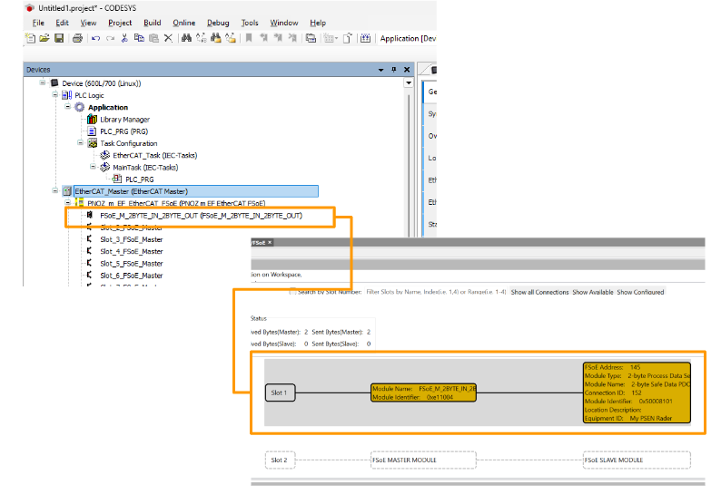
The cyclic data transmission between the Analysing unit acting as fieldbus master and slave is performed via Process Data Objects (PDOs). The Analyzing unit has one slot that can be plugged in exclusively for various PDOs to transmit safety-related process data.
- 2-byte Safe Data PDOs (module ID: 0x50008101)
- RxPDO 2-byte Data Process – index 0x1600
- TxPDO 2-byte Data Process – index 0x1A00
- 4-byte Safe Data PDOs (module ID: 0x50008102)
- RxPDO 4-byte Data Process – index 0x1601
- TxPDO 4-byte Data Process – index 0x1A01
- 16-byte Safe Data PDOs (module ID: 0x50008103)
- RxPDO 4-byte Data Process – index 0x1601
- TxPDO 16-byte Data Process – index 0x1A02
Process data not related to safety is also available. (only if enabled)
- 16-byte Non-Safe Data PDOs
- TxPDO Non-Safe Data Process – index 0x1A03
Addressing
To identify FSoE devices in the network, a unique FSoE address in the range from 1 to 65,534 is required; FSoE addresses can be assigned to devices with the PSEN rd1 configurator.
Watchdog
The protocol includes a watchdog timer that works in conjunction with the master frame and checksum to ensure optimal secure connection and error prevention monitoring over each FSoE frame transmission. The watchdog time is individually parameterized in the range of 100 to 1000 ms for each slave using the FSoE master.
Implementation
Pilz Side
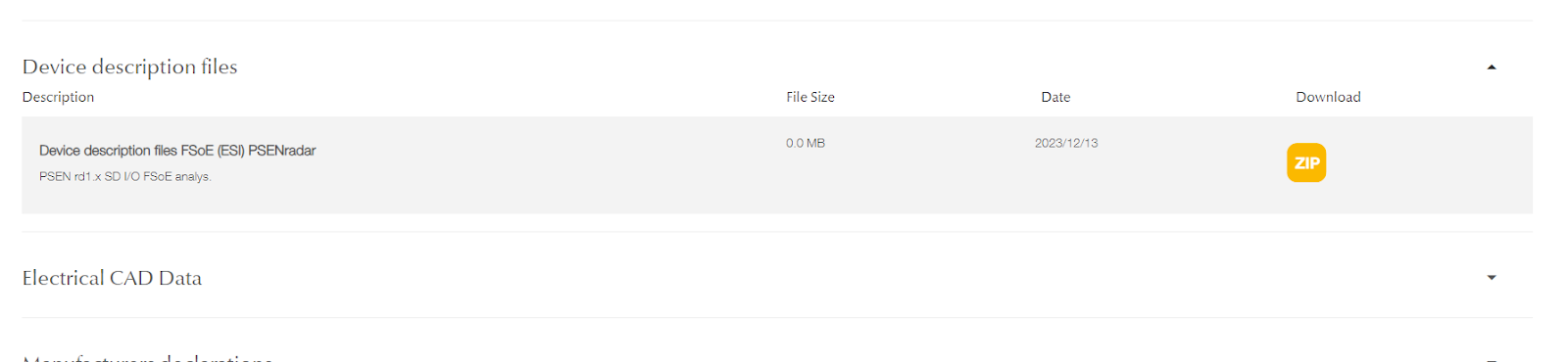
Download ESI File
Download the ESI File for the PSEN-rd1-x system at the following Link.
PNOZmulit Configurator
The next step is to set up the PNOZ Controller project.
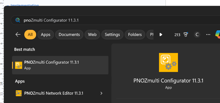
Start
Launch the PNOZmulit Configurator tool.
Hardware Configuration
Add the Hardware used in this article to your project. The Base Unit used in this article is Base Unit PNOZ m B1.
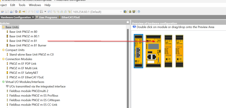
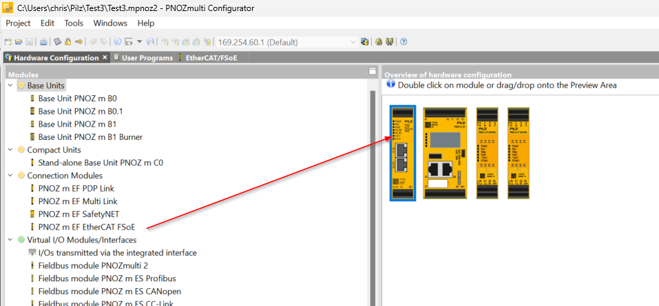
Of course, FSoE communication with PSEN rd1.x is required, so add Connection Module>PNOZ m EF EtherCAT FSoE.
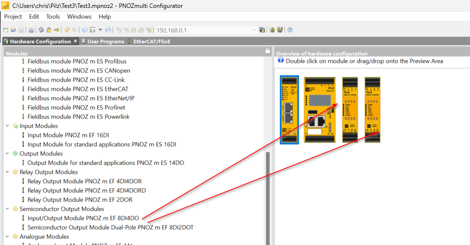
Although not actually used in this article, add two Semiconductor Output Module>Input/Output Module PNOZ m EF 8DI4DO
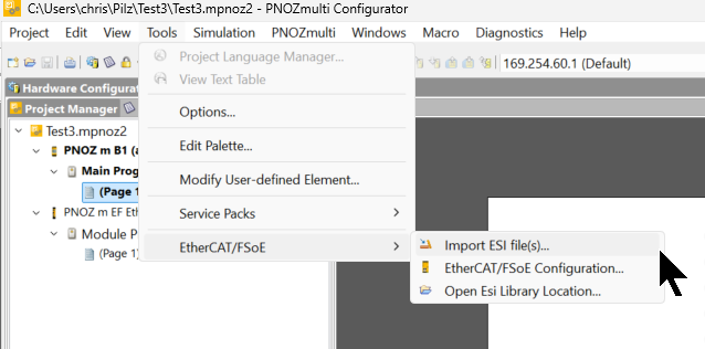
Import ESI File
Click on Tools>EtherCAT/FSoE>Import ESI File and import the PSEN rd1.x ESI File.
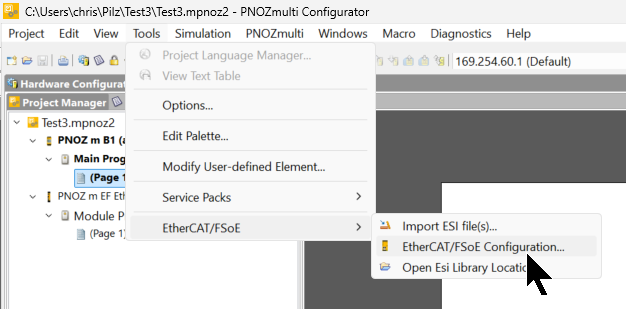
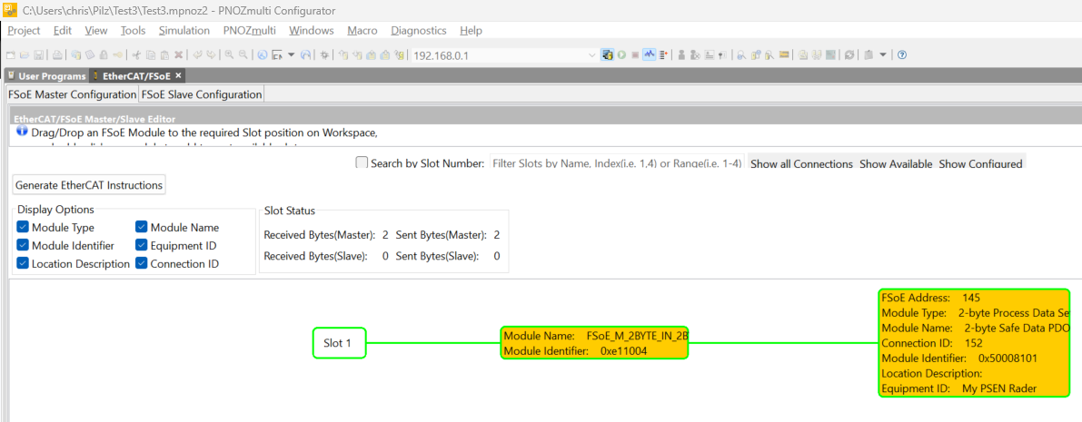
EtherCAT/FSoE Configuration
Next, click on Tools>EtherCAT/FSoE>EtherCAT/FSoE Configuration to set up the EtherCAT network.
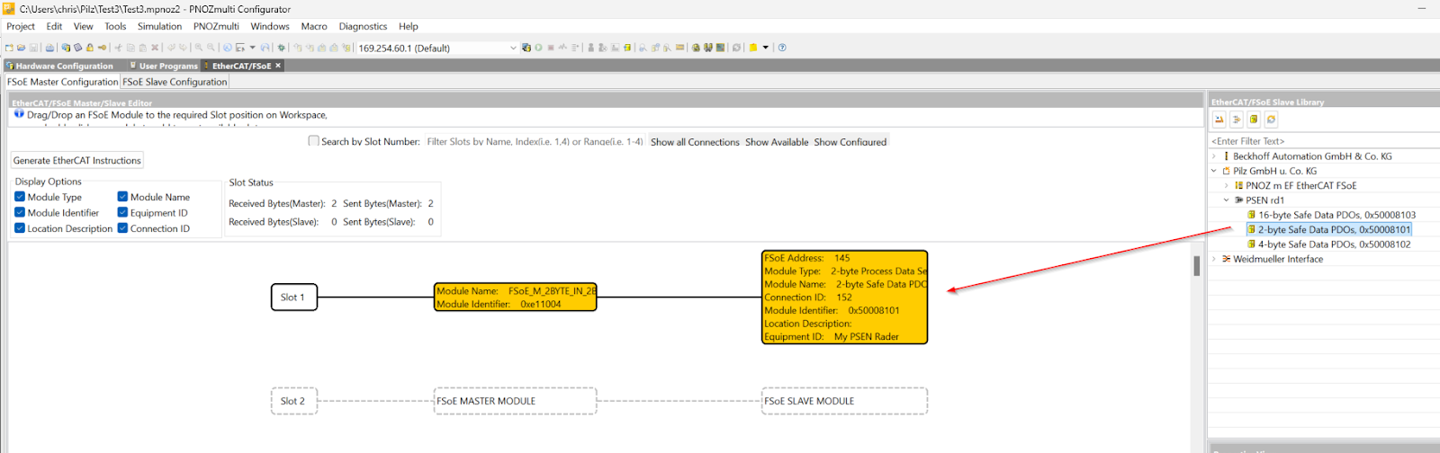
Add the PSEN rd1.x that you just imported from the EtherCAT/FSoE Slave Library to the network. We will use 2 Bytes of input/output FSoE data in this article.
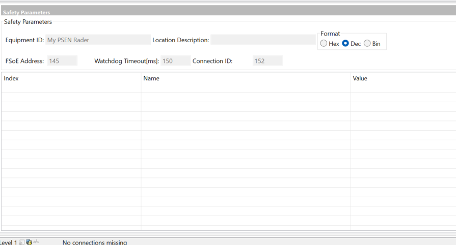
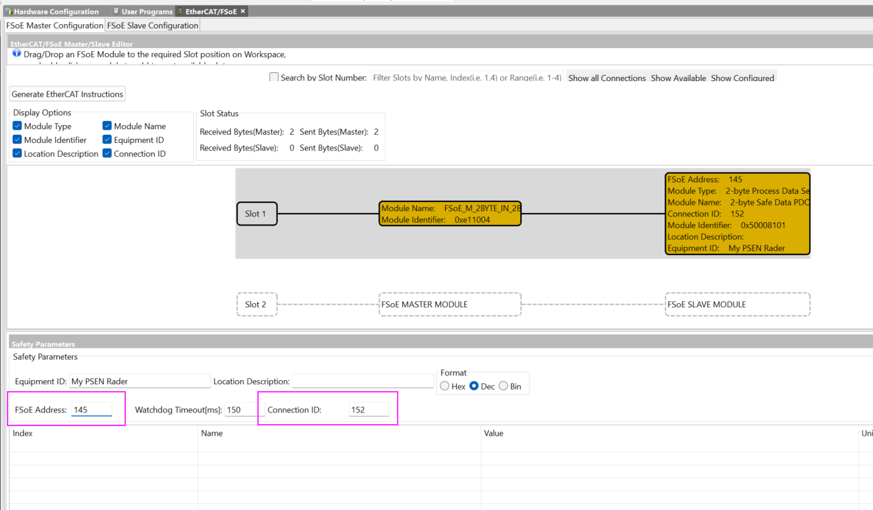
FSoE Address/Connection ID
Match the FSoE address to the number set in PSEN rd1.x. Set the Connection ID so that it is not covered in the network.
Donwload
To Download a project, click PNOZmulit>Project Manager.
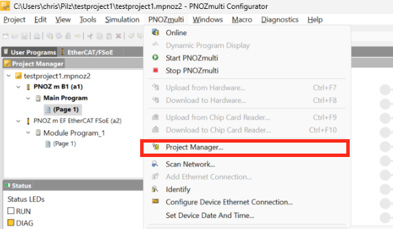
The Download screen appears.
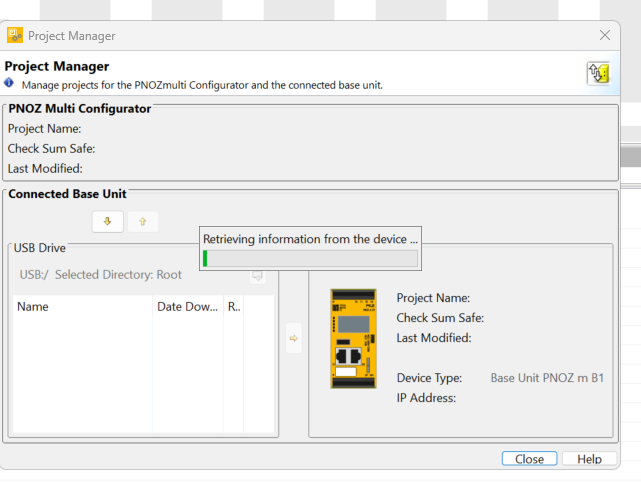
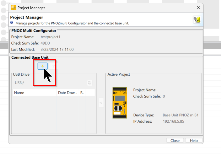
Click the button in the red frame to download the project.
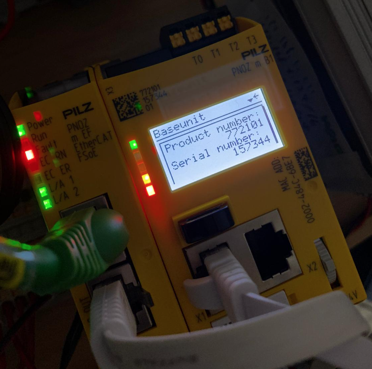
Enter the Order Number and Serial Number of the CPU.

Order Number and Serial Number can be checked from the CPU screen.
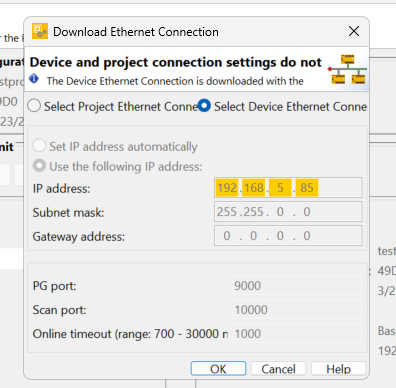
To change the Ethernet Connection, click “Select Device Ethernet Connection” and press OK to proceed.
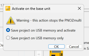
Select “Save project on USB Memory and activate” and press Ok to proceed.
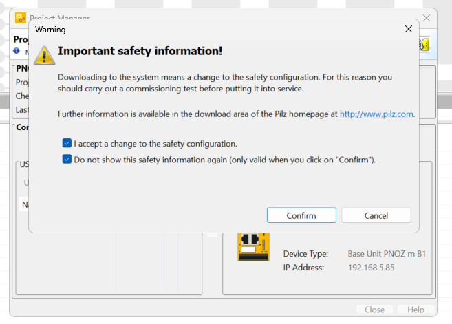
Check the notes and proceed with Confirm.
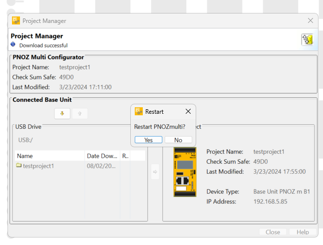
Please wait a moment as the Download starts.
The “Do you want to restart the PNOZmulit CPU from the tool? confirmation screen will appear, and proceed with Yes.
PSEN Side
The next step is to configure the PSEN rd1.x system.
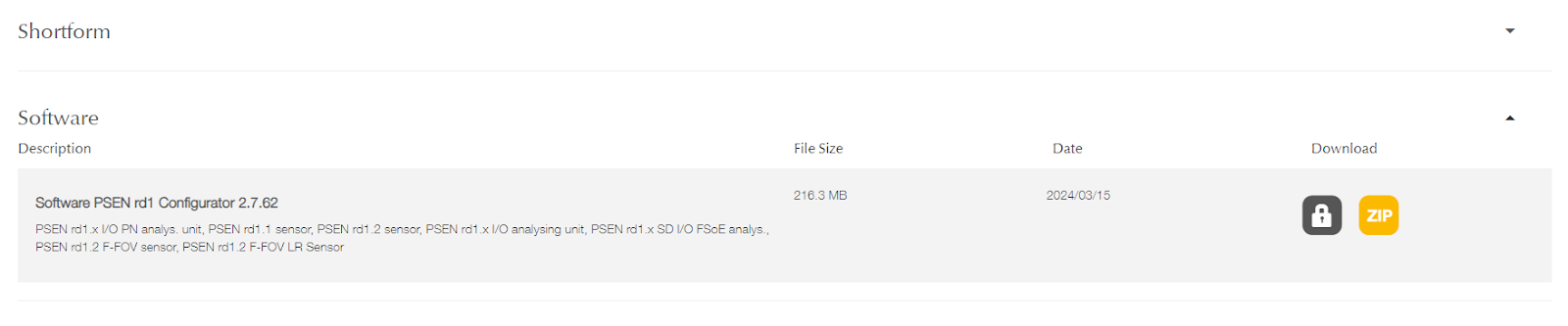
Download Tools
Download the PSEN rd1.x Configurator Tools from the Pilz website. The tool has the following features
- Configure the system.
- Create the configuration report.
- Check system functioning.
- Download system log.
To use the configurator, PSEN rd1.x must be connected to a computer with a data USB cable or an Ethernet cable if an Ethernet port is available.
Factory Reset
Press and hold the button below to return PSEN rd1.x to factory settings.

Start
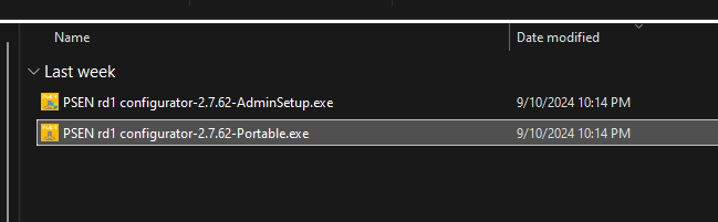
The tool downloaded from Pilz HP has an Installed version or a Portable version, which can be used depending on the operation.
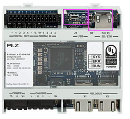
Connect via USB/Ethernet
Connect the USB Port or Ethernet as shown in the figure below to the PC.
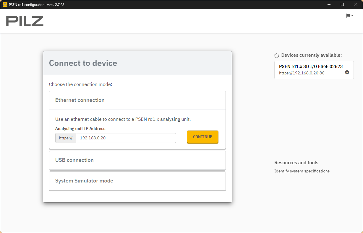
Start Tool
Select Ethernet connection, enter the IP address of PSEN rd1.x and press CONTINUE to proceed. (Default IP address is 192.168.0.20)
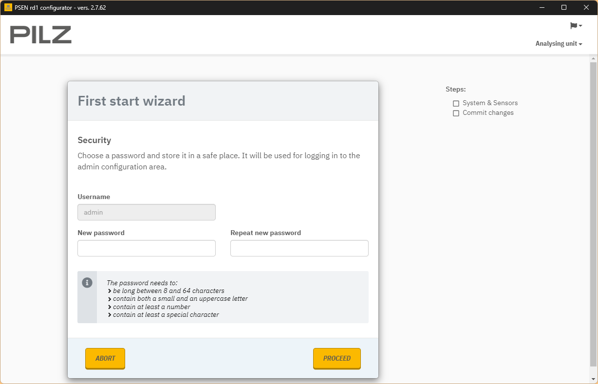
Setup Password
Set Password to PSEN rd1.x back to factory settings.
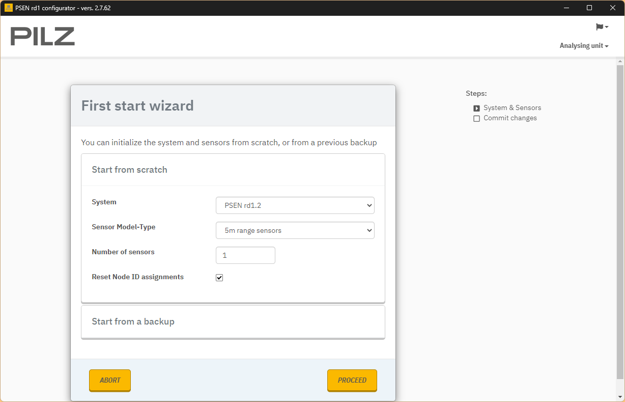
Hardware Configuration
Set the Hardware to be used for Hardware and proceed with PROCEED.
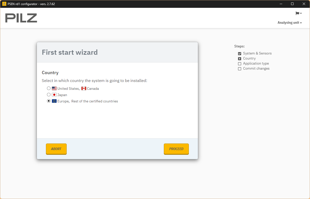
Country
Select the country where PSEN rd1.x will actually be used and proceed with PROCEED.
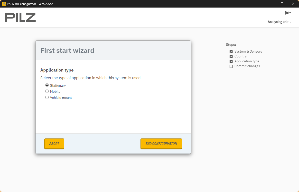
Stationary
Let’s set up the PSEN rd1.x application and apply the settings in END CONFIGURATION.
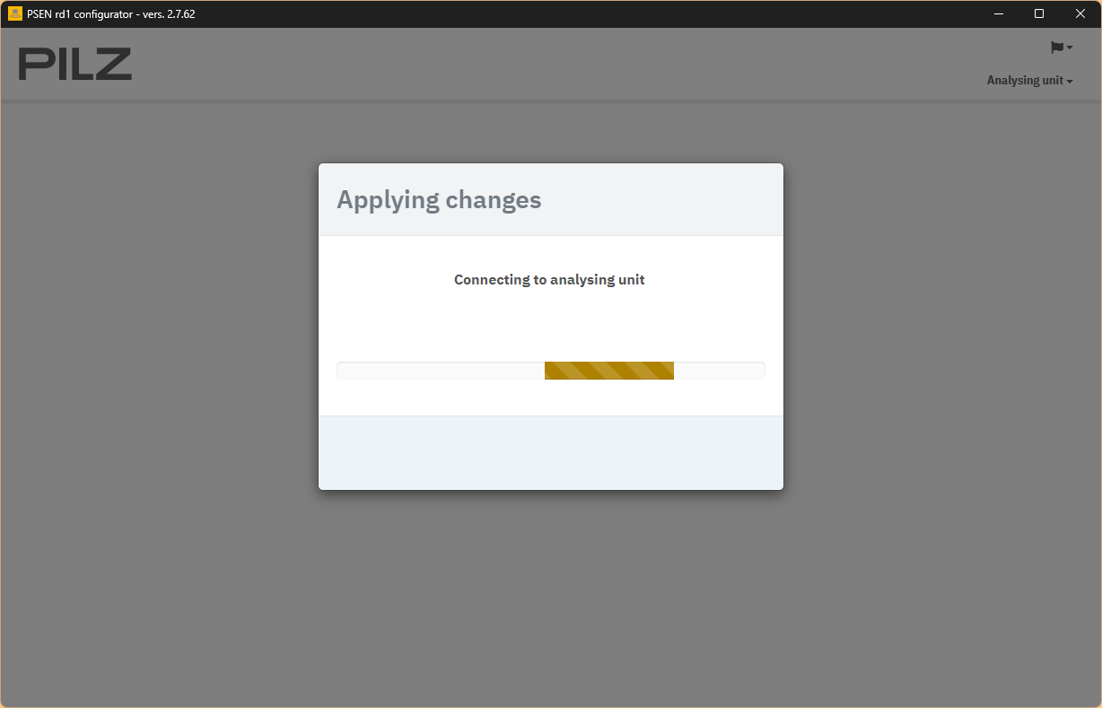
Please wait a moment…
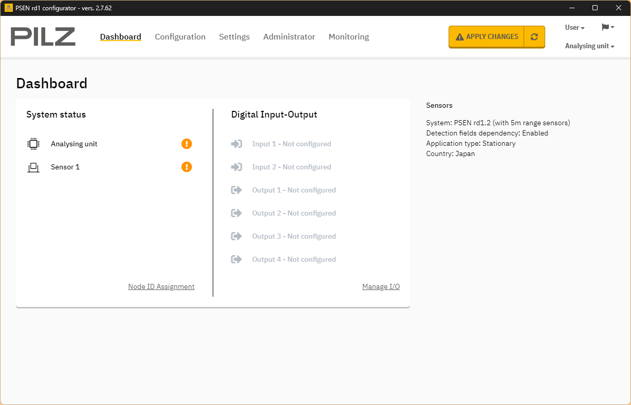
Result
Done!
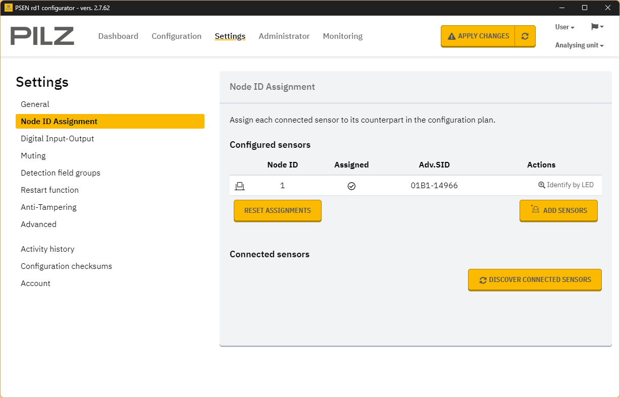
Node ID Assignment
Set or reset the CAN ID of the Rader sensor in Settings>Node ID Assignment.
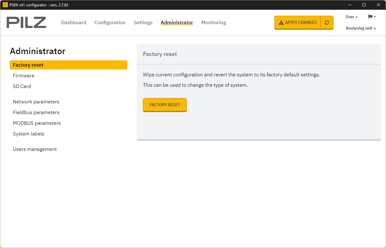
Factory Reset
It is also possible to restore the device to factory settings by going to Administrator>FACTORY RESET.
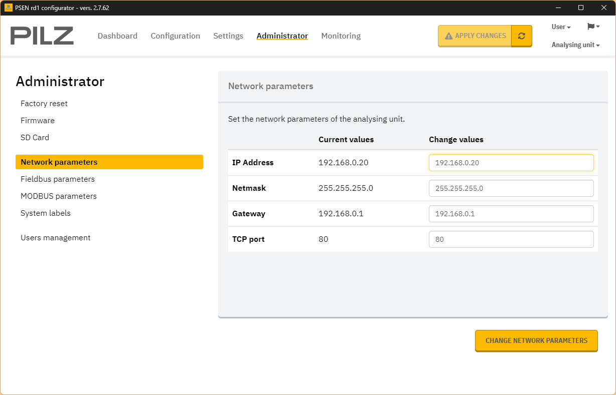
Network parameters
You can change the IP address of the device in Network Parameters.
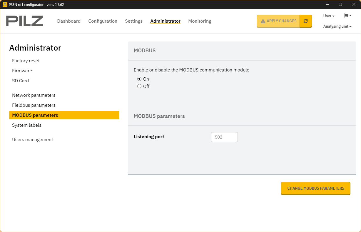
MODBUS Parameters
You can enable the device’s Modbus TCP Server with MODBUS Parameters.
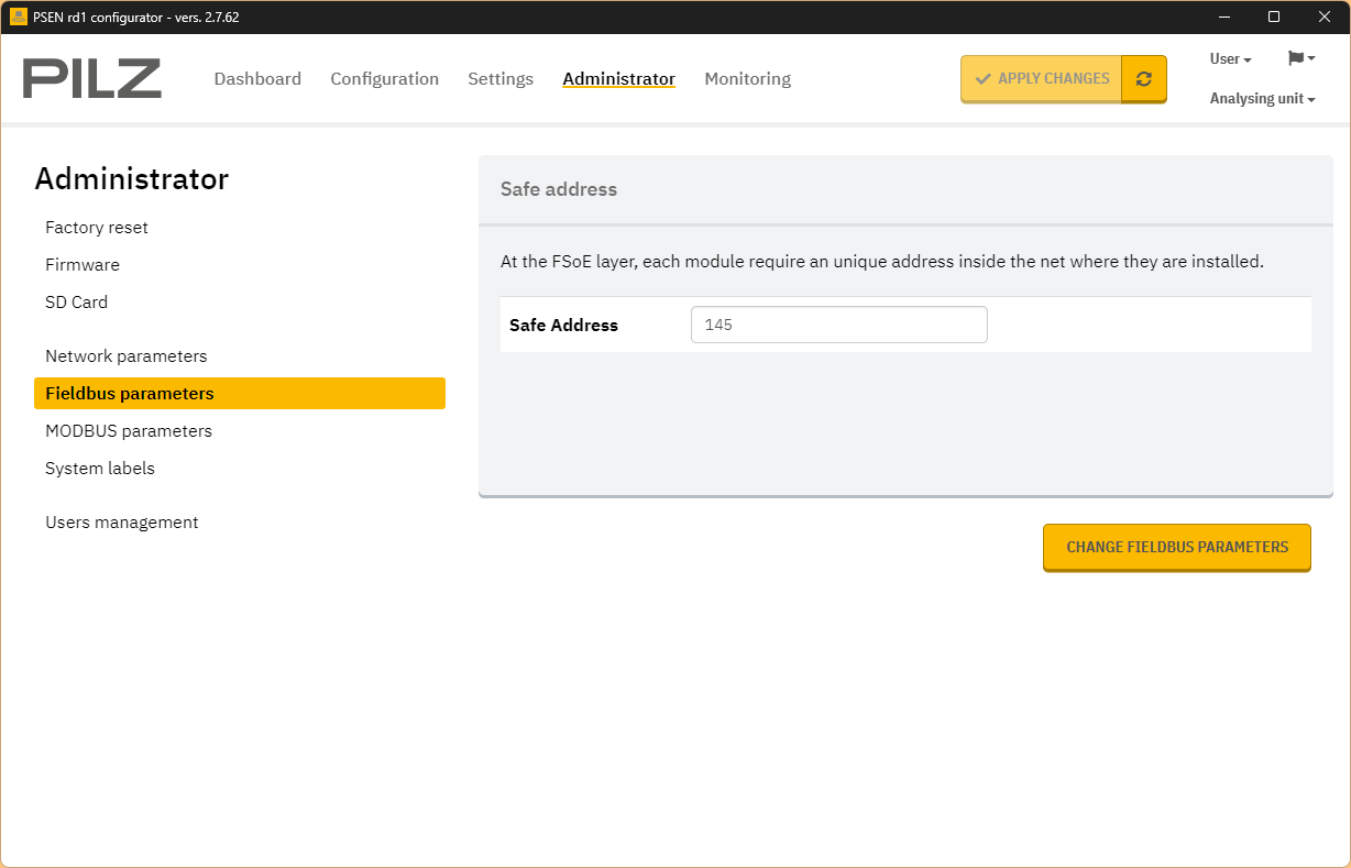
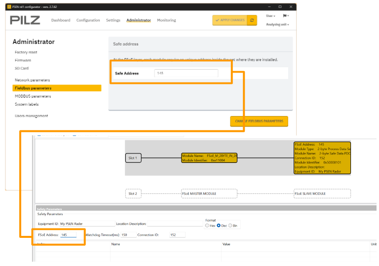
Fieldbus Parameters
Set the FSoE address of PSEN rd1 in Fieldbus Parameters.

Its FSoE address should be matched to the PNOZ Controller side.
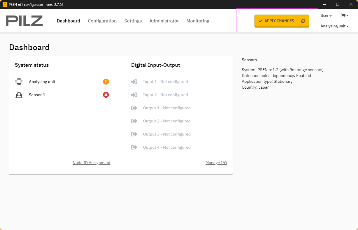
Download
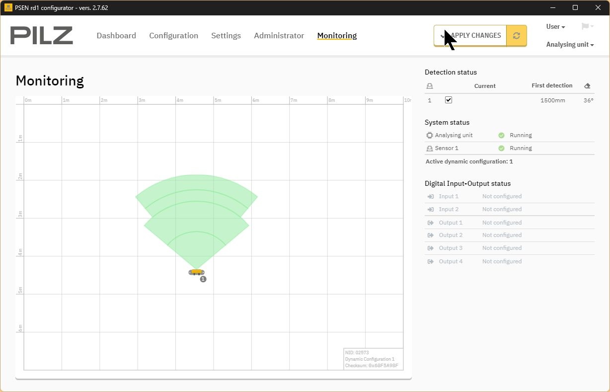
Finally, click APPLY CHANGES to apply the Configuration.
Codesys Side
Next, prepare the Codesys side. This is the Codesys IDE version used in this article.
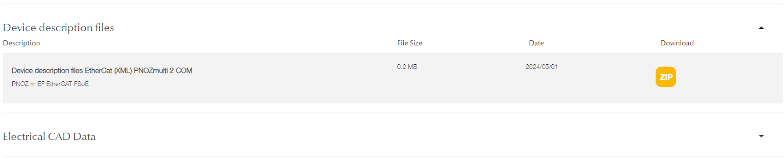
Download ESI File
Donwload the ESI File for PSENradar and PNOZ-m-EF-EtherCAT-FSOE from the Pilz HP.
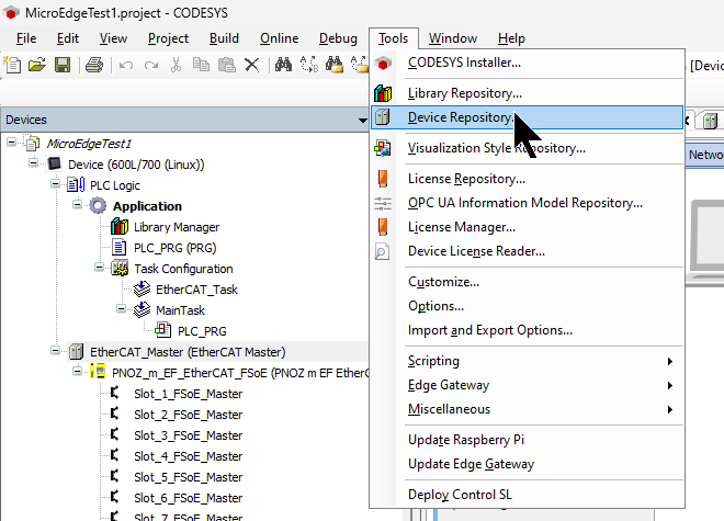
Install ESI File
To install the ESI File, click Tool>Device Repository.
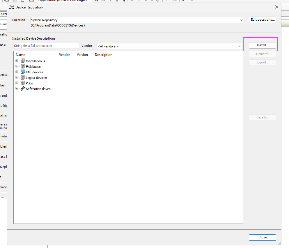
Click “Install” to install the ESI File you have just downloaded.
EtherCAT Configuration
The next step is to build an EtherCAT network with Codesys.
Add EtherCAT Master
Right-click on Device>Add Device to add a communication Driver.
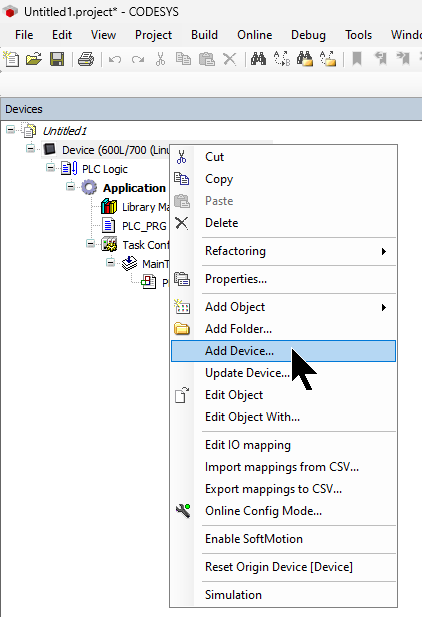
Add Fieldbus>EtherCAT>Master>EtherCAT Master.
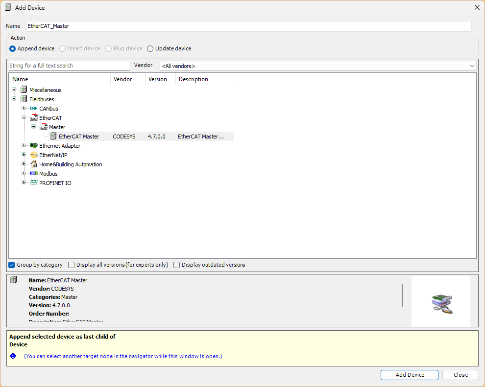
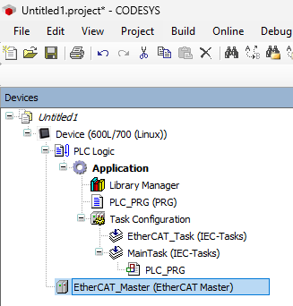
Done!EtherCAT Master has been added.
Configure Adapter
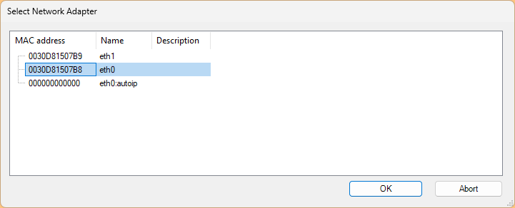
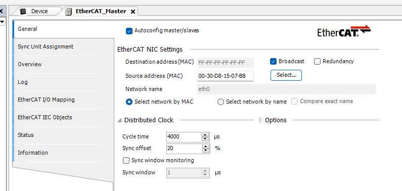
Click on the EtherCAT Master that was just added and Tab to General and click Select.
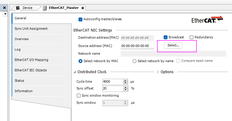
Configure the Ethernet Adapter you want to use as EtherCAT Master in the actual application.
Done!
Scan Devices
This time we will use Codesys’ EtherCAT automatic SCAN function.
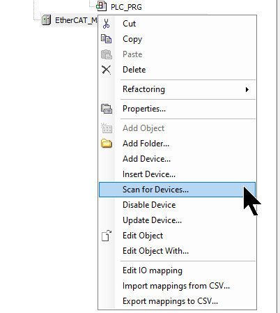
Done!Now that all EtherCAT Slaves have been searched, let’s duplicate all settings to the project with Copy All Devices to Project.
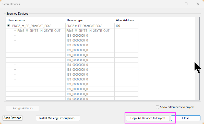
Done!
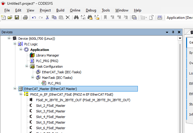
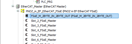
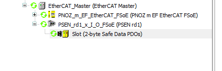
Input/output data of 2BYTES was also detected in PNOZ_m_EF_EtherCAT_FSoE.
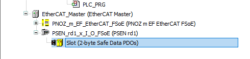
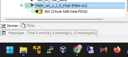
PSEN rd1 also detected 2 BYTES input/output data.

PLC Logic
The next step is to create a PLC project.
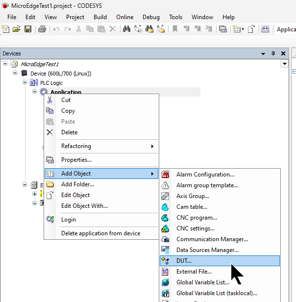
ADD DUT
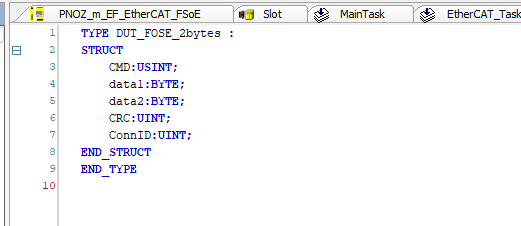
Add Obejct>DUT to create the structure.
Enter the name of the DUT.
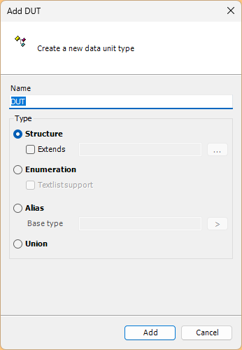
Define the FSoE data structure for 2 BYTES.
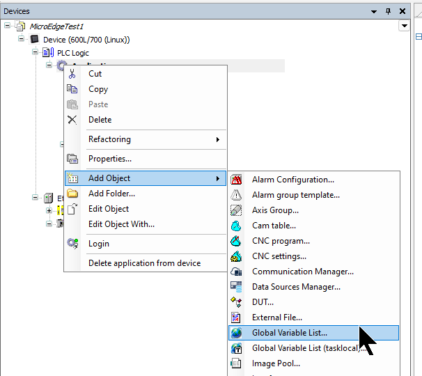
Add GVL
Create a Global Variable List.
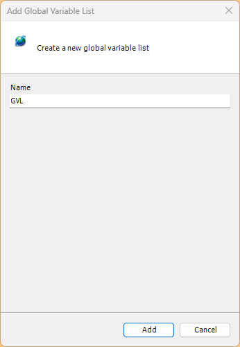
Enter the GVL name.
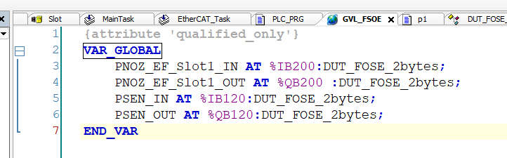
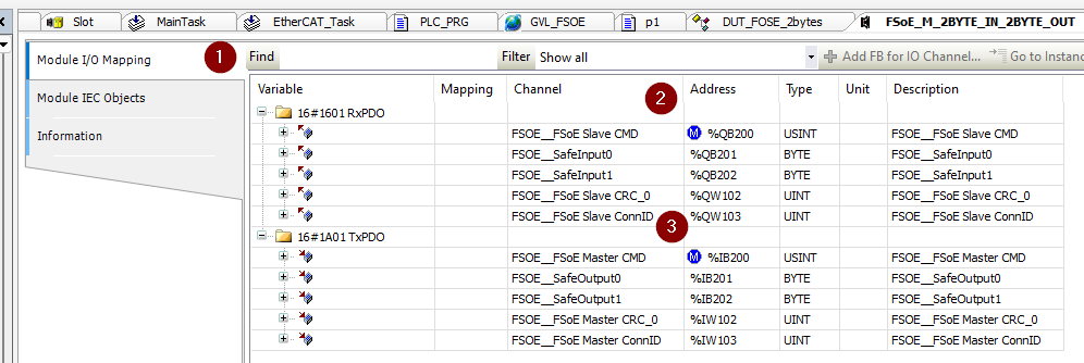
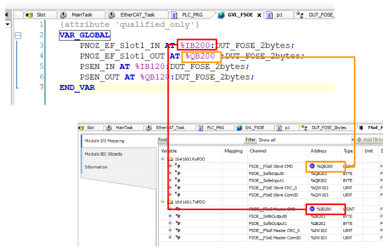
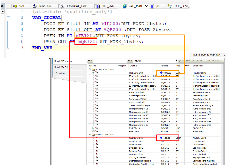
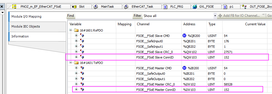
Defines 2 Bytes FSoE input/output data for PNOZ_m_EF_EtherCAT_FSoE and PSEN rd1. Note that all FSoE variables are also assigned absolute addresses.
MAIN PROGRAM
Let the program Loopback the input data of PSEN rd1 as it is as output data of PNOZ_m_EF_EtherCAT_FSoE, and let the input data of PNOZ_m_EF_EtherCAT_FSoE Loopback the output data of PSEN rd1.
| GVL_FSOE.PNOZ_EF_Slot1_OUT:=GVL_FSOE.PSEN_IN; GVL_FSOE.PSEN_OUT:=GVL_FSOE.PNOZ_EF_Slot1_IN; |
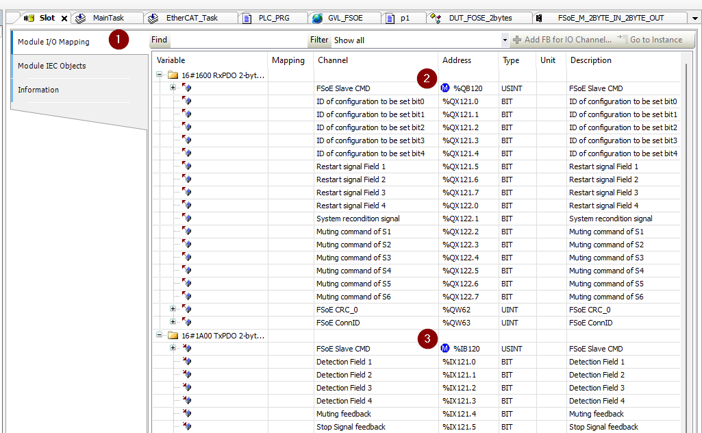
Mapping‐PNOZ
Force the frontal address of FSOE_Slave_CMD and FSOE_Master_CMD to match the GVL.
Mapping‐PSEN
Force the frontal address of FSOE_Slave_CMD and FSOE_Slave_CMD to match the GVL.
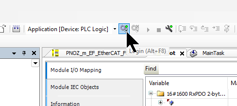
Download
Finally, download the project to Runtime.
Result
Done!I was able to communicate with Codesys and PNOZ_m_EF_EtherCAT_FSoE/PSEN rd1.
FSoE communication between PNOZ_m_EF_EtherCAT_FSoE and PSEN rd1 is also established.
If you do not know the FSoE address of PSEN rd1, click on PSEN rd1.
The FSoE address can be found in the Safety Diagnosis item.
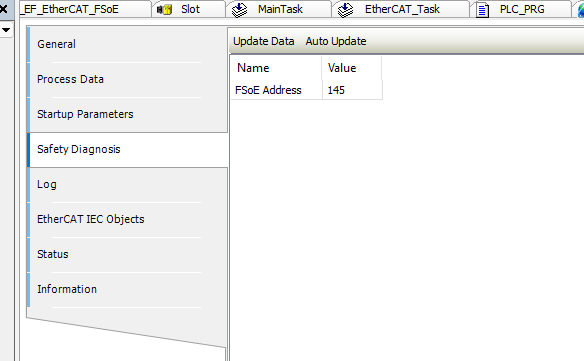
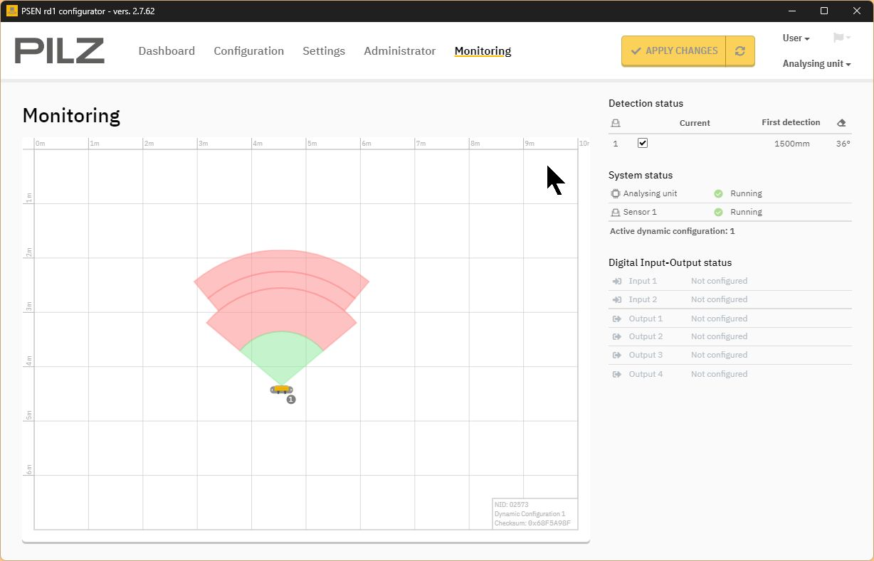
PSEN rd1 is also working properly.