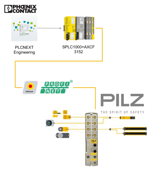
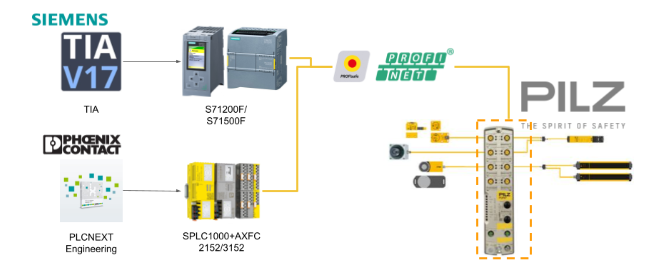
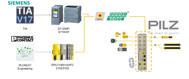
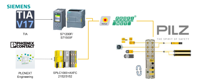
In this second episode of Pilz’s PDP67, we will start up F-HOST using the AXCF3152xSPLC1000 combination to communicate Profisafe with Pilz’s PDP67. I will also explain the concept and calculation of Watchdog Time, which is important when using Profisafe communication.
Let’s get started!
Reference Link
Some Tips about Profisafe..
Safety Function Response Time, SFRT
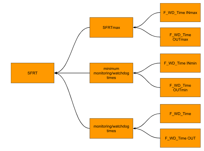
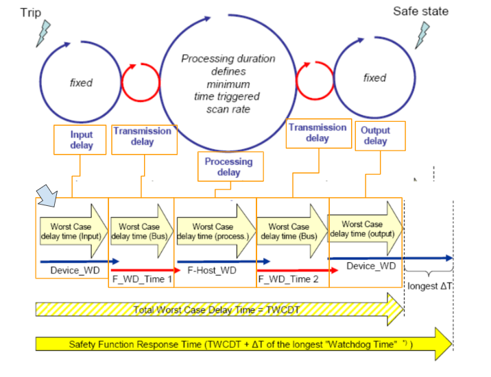
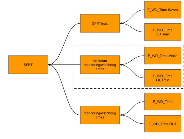
To define SFRT (Safety Function Response Time), there are three main elements shown in the figure below.They are SFRTmax, minimum monitoring/watchdog times, and monitoring/watchdog times. I would like to touch on these elements in the following sections.
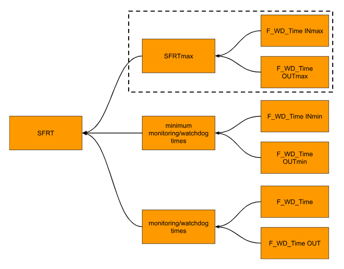
Determining SFRTmax and F_WD_Time INmax/ F_WD_Time OUTmax
SFRTmax is the maximum permissible response time of a safety function, which is determined by the actual safety application implementation, and F_WD_Time INmax is the upper monitoring limit of an individual safety function.
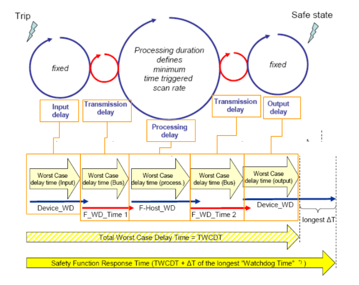
From input to output..
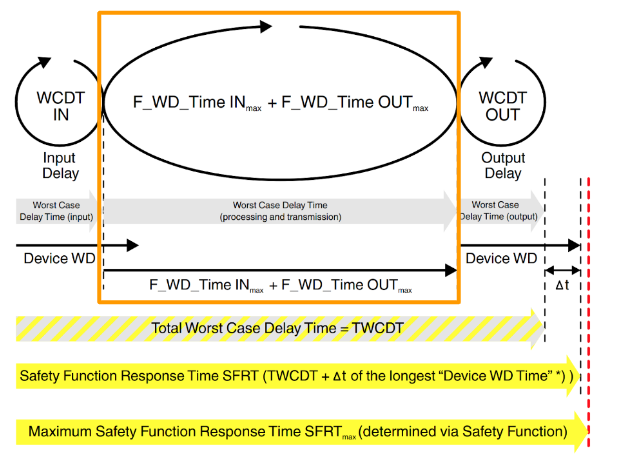
The application must determine the maximum SFRT for each safety function implemented. This maximum allowable SFRT value also applies when PROFIsafe and SPLC 1000 are used together and involved in a safety function. The figure below shows the actual delay from the safety input to the safety output only.
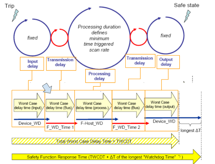
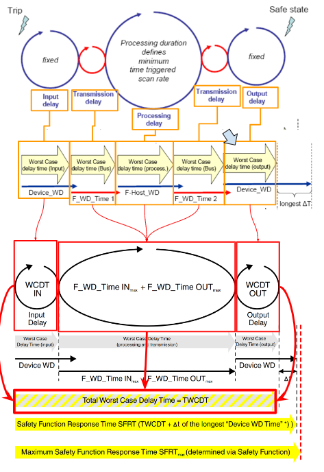
WCDT IN
For maximum delay time of F-Device with WCDT IN input function, please refer to the F-Device specifications.
F_WD_Time_1
F_WD_Time INmax Monitoring Time The value of F_WD_Time (watchdog time), not to exceed SFRTmax, can be set as the maximum value for an individual F-Device with input functions involved in safety functions.
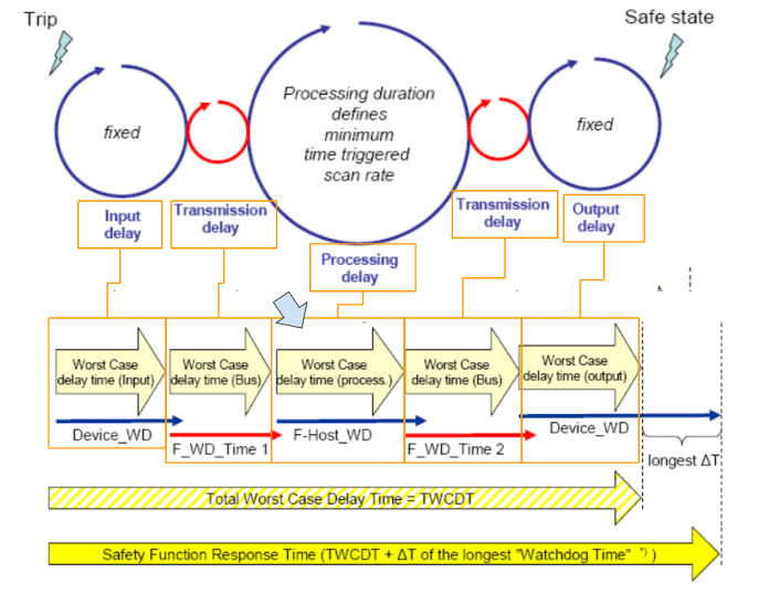
F_Host_WD
F_Host (SPLC1000 in this article) safe application processing time is monitored by F_Host_WD.
F_WD_Time_2
F_WD_Time OUTmax Monitoring Time -The value of F_WD_Time (watchdog time), not to exceed SFRTmax, can be set as the maximum value for an individual F-Device with output functions related to safety functions.
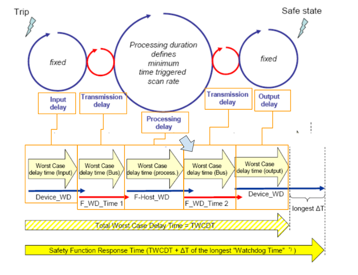
WCDT OUT
For the maximum delay time of F-Device with WCDT OUT output function, please refer to the F-Device specifications.
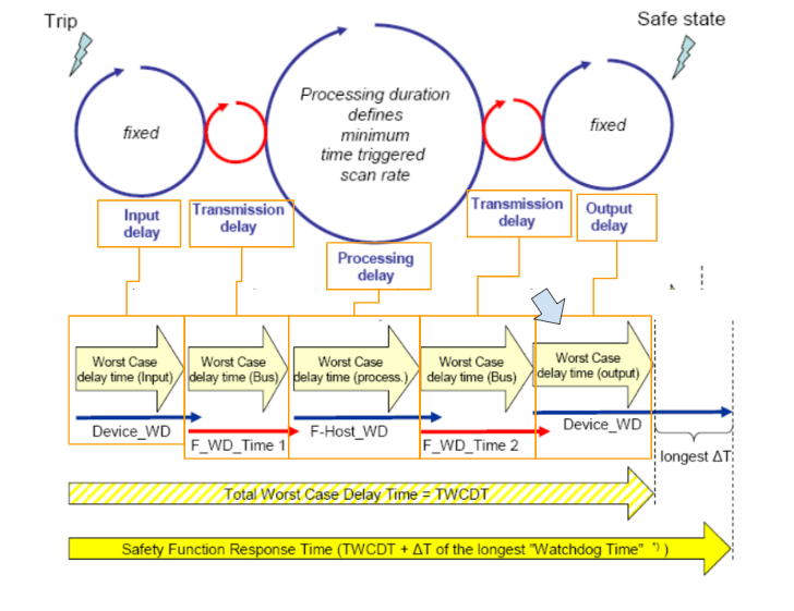
TWCDT (total worst case delay time)
The TWCDT (total worst case delay time) will be the sum of the maximum Runtime that may occur in an individual element during normal operation, and the individual elements will be:
- (PROFIsafe) F-Devices
- data transfer
- PROFIsafe via PROFINET for all net components
- All network components with their sub-systems (e.g. Axioline F Bus of Phoenix Contact).
The SPLC1000 Manual states that runtime, cycle time, and watchdog time (processing delay and F-Host_WD) are not really relevant when determining SFRT when using the SPLC 1000, since F-Host / SPLC 1000 processing is closely synchronized.(Reference from Manual)
The Calculation of Actual SFRT
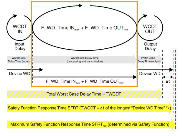
SFRT is the response time of the safety function of the SFRT PROFIsafe system and the SPLC 1000. Before setting the MAX SFRT, the current SFRT must first be known, and the method for calculating the SFRT applicable to PROFIsafe is described in the PROFIsafe specification.
| SFRT = WCDT IN + (F_WD_Time INmax + F_WD_Time OUTmax) + WCDT OUT |
And this value should be smaller than SFRT.
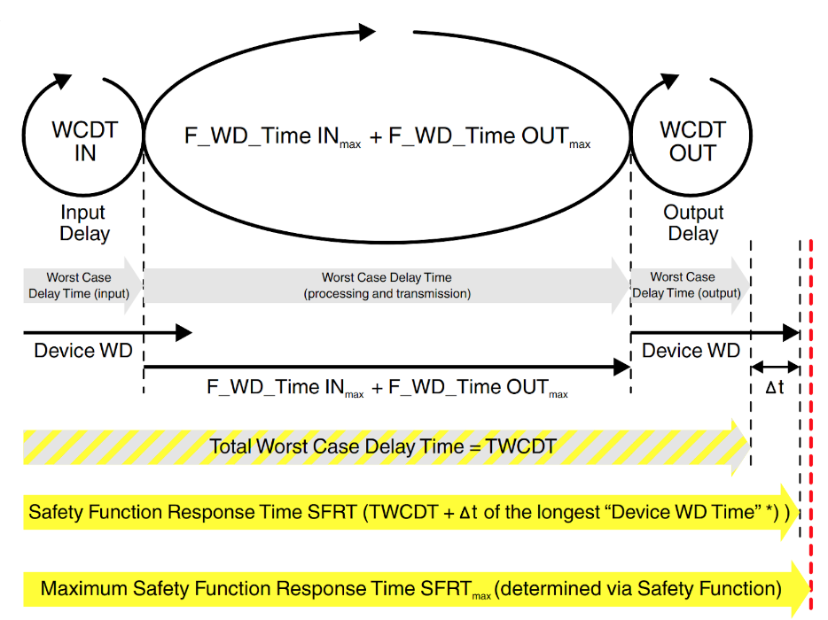
As you may have noticed, the Wrost Case Delay Time in the middle is the sum of F_WD_Time INmax and F_WD_Time OUTmax. The result is the maximum internal processing time required for Point to Point communication via PROFIsafe between a PROFIsafe input device and a PROFIsafe output device using SPLC 1000.
The Calculation of Maximum permissible watchdog times
Now we know the calculation of SFRT.
| SFRT = WCDT IN + (F_WD_Time INmax + F_WD_Time OUTmax) + WCDT OUT |
Therefore, the sum of F_WD_Time INmax and F_WD_Time OUTmax must be smaller than the sum of SFRTmax and WCDT IN and WCDT OUT.
| F_WD_Time INmax + F_WD_Time OUTmax ≤ SFRTmax – WCDT IN – WCDT OUT |
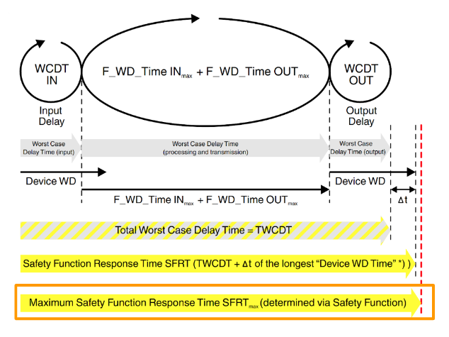
The Calculation of Maximum SFRT
So the calculation of Maximum SFRT is like this. The Permit Time depends on the application.
| SFRT = WCDT IN + (F_WD_Time INmax + F_WD_Time OUTmax) + WCDT OUT + permit Time |
Determining F_WD_Time INmin/F_WD_Time OUTmin
F_WD_Time must be determined by the user depending on the application, and in the case of PLCNEXT it is set from the PLCnext Engineering Software.When communicating with F-Host (SPLC 100) and F-Devices in Profisafe, F_WD_ To ensure that Time is observed, F-Devices perform monitoring independently by both F-Host (SPLC 1000) and F-Devices.
Note that if F_WD_Time is too short for safety-related communication relationships, the system or application will be unusable. This is because safety communication via PROFIsafe cannot be established unless the value of F_WD_Time is greater than the maximum round-trip transfer time from F-Host to F-Device. In addition to the transmission time on the network (PROFINET cycles), other factors such as the execution time of the internal stack and firmware, delays due to subsystem buses (e.g., device buses in a module I/O system) must also be considered.
Note that if F_WD_Time is too short in safety communication, the system or application will trigger the Watchdog function and become unusable.
- Transmission time on the network (PROFINET cycle)
- Internal stack and firmware run time
- Delays due to subsystem buses (e.g., device buses in a module I/O system) and other factors must also be considered.
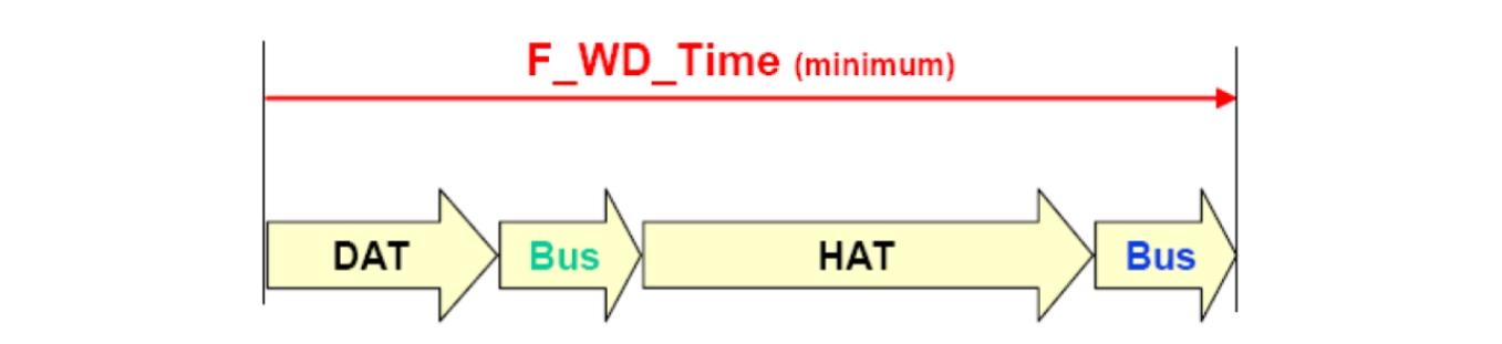

DAT
For DAT, please refer to each manufacturer’s specifications in Cycletime on F-Device.
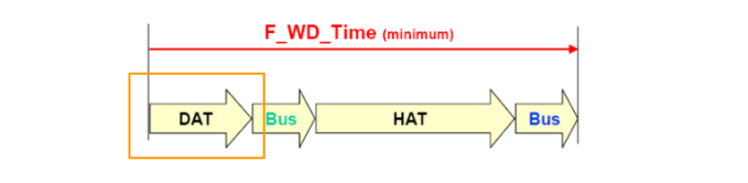
Bus
Bus Runtime is the sum of internal Bus Runtime, external Bus Runtime, etc.
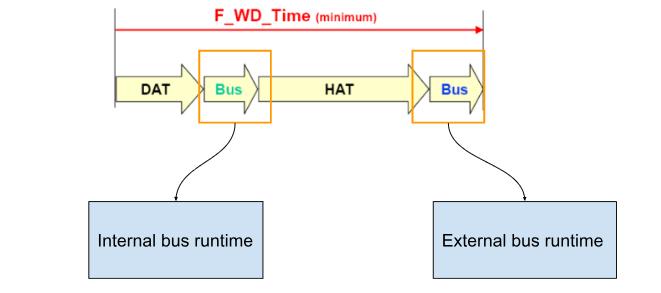
External bus runtime in the network
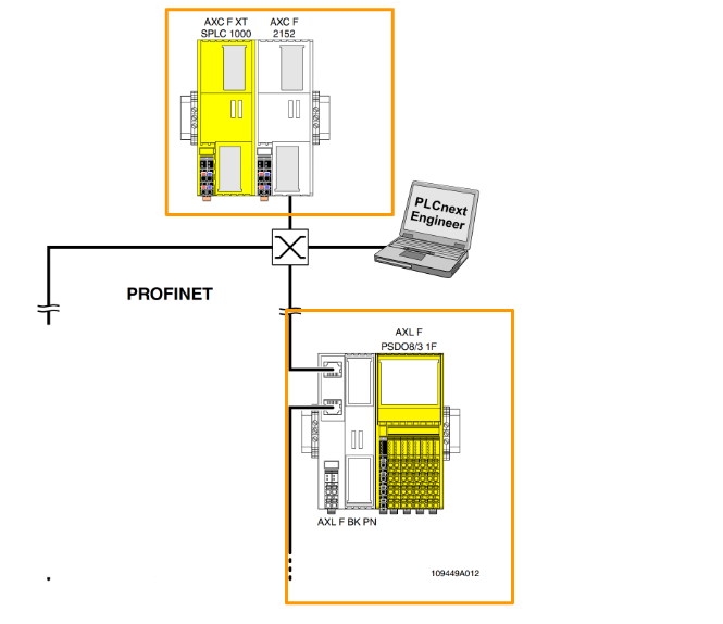
To explain the external bus runtime, let us first assume that we have the following example configuration.
Update time of the I/O data between PROFINET controller and device
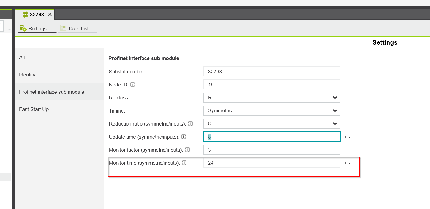
The update time setting of the I/O data between the PROFINET controller and the device is the result of the “Reduction ratio” parameter x “Monitor factor” parameter. The result (or monitor time) is the time in seconds.
The result (or monitor time) is that if no cyclic data is sent within the specified time, the communication relationship is considered broken.
The settings for the “Reduction ratio” parameter x “Monitor factor” parameter are as follows Open the PDP67>PROFINET IO used in this article.
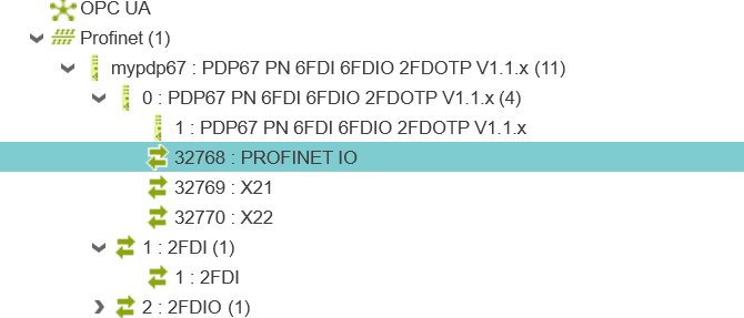
Open the Profinet interface sub module and configure External bus parameters such as Timing.
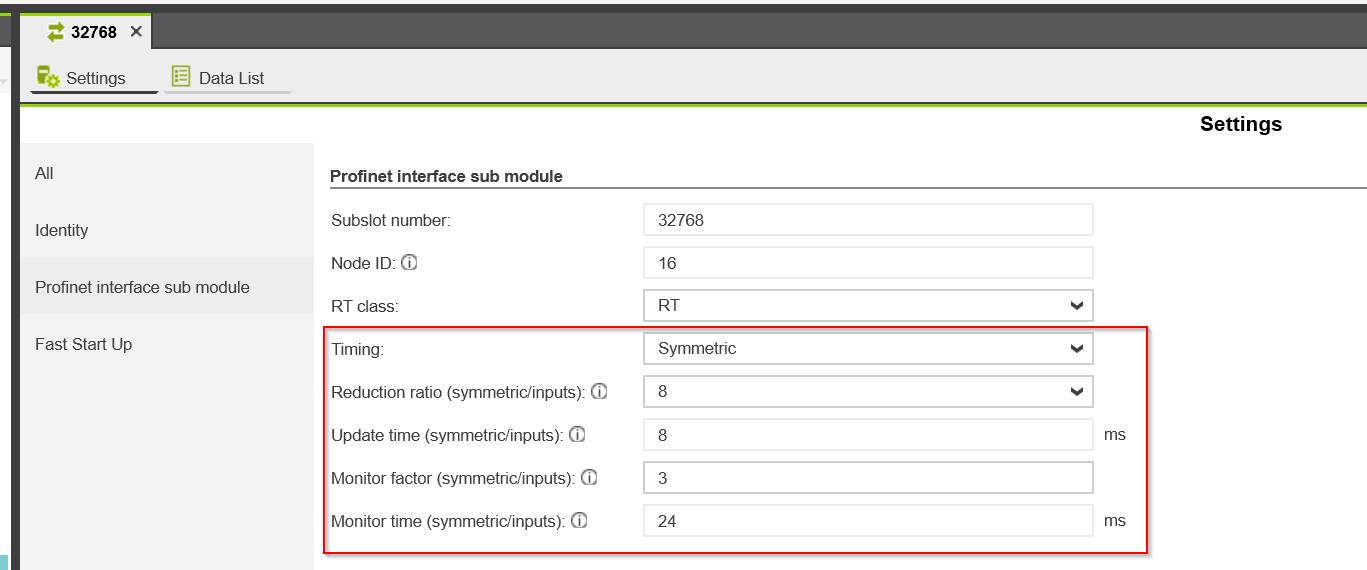
For example, to set the Reduction Ratio, click on Drop List.
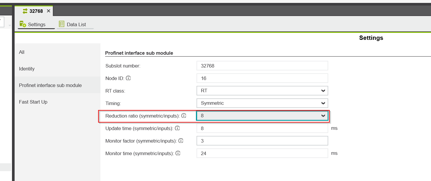
Thus, it can be set as 1, 2, 4, 8, 16….
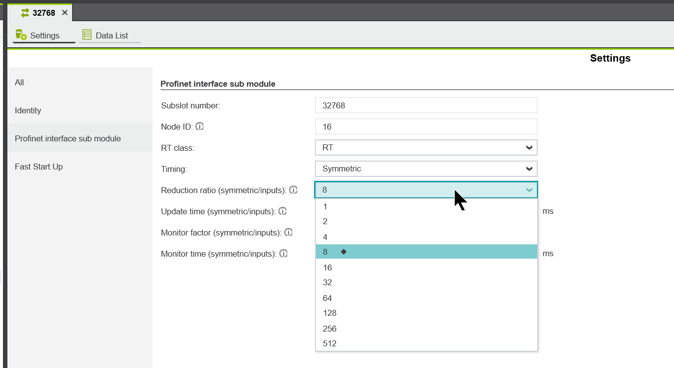
Next, the Monitor Factor can be set directly from 3 to 255.
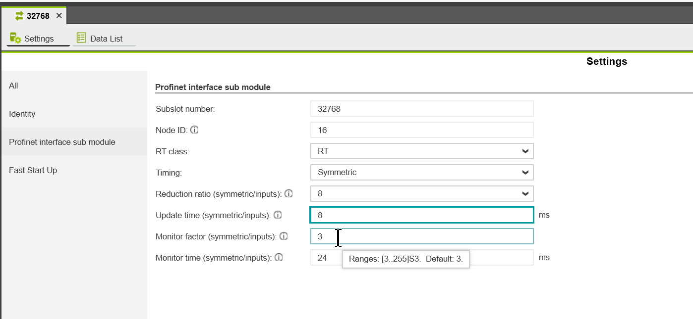
Currently, the reduction ratio = 8 and monitor factor = 3, so the monitor time is = 8×3 = 24 ms.
Relevant runtime components
It is the bus head (bus coupler) of the module system and the associated runtime component of the backplane bus.
Any runtimes within infrastructure components
And please refer to each manufacturer’s specification sheet for the part Runtime of F-Device.
Internal bus runtime
Internal bus runtime Included in the following parts:
- SPLC 1000 installed on left side
- Main PLCnext Control
- Safety-related Axioline Smart Elements installed on the right side
- Internal bus of Axioline F module installed on the right side
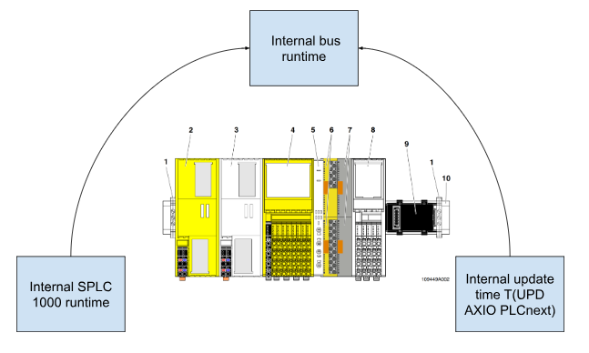
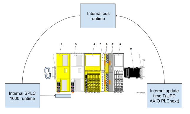
Internal SPLC 1000 runtime
Internal SPLC1000 Equivalent to one cycle of RuntimeSPLC 1000 (TZSPLC) and can be set from 5 ms to 15 ms with PLCnext Enginee Software (Default is 5 ms).
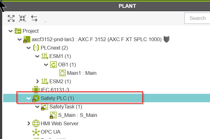
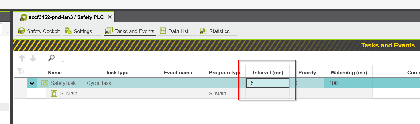
To set the Cycle time (TZSPLC) for SPLC1000, open the Safety PLC in Projet.
It can be set directly from the Interval(ms) field on the Task and Events tab.
Internal update time TUPD AXIO PLCnext
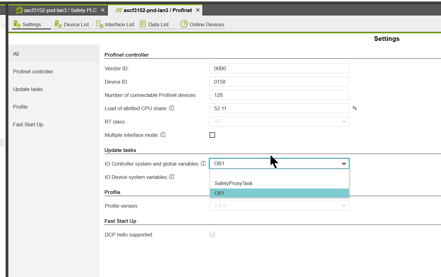
Axioline F local bus cycle and PLCnext firmware update time (TUPD AXIO PLCnext) can be set from Update tasks in Plcnext Engineering Software.
To change the TUPD AXIO PLCnext setting, open Project>Profinet.
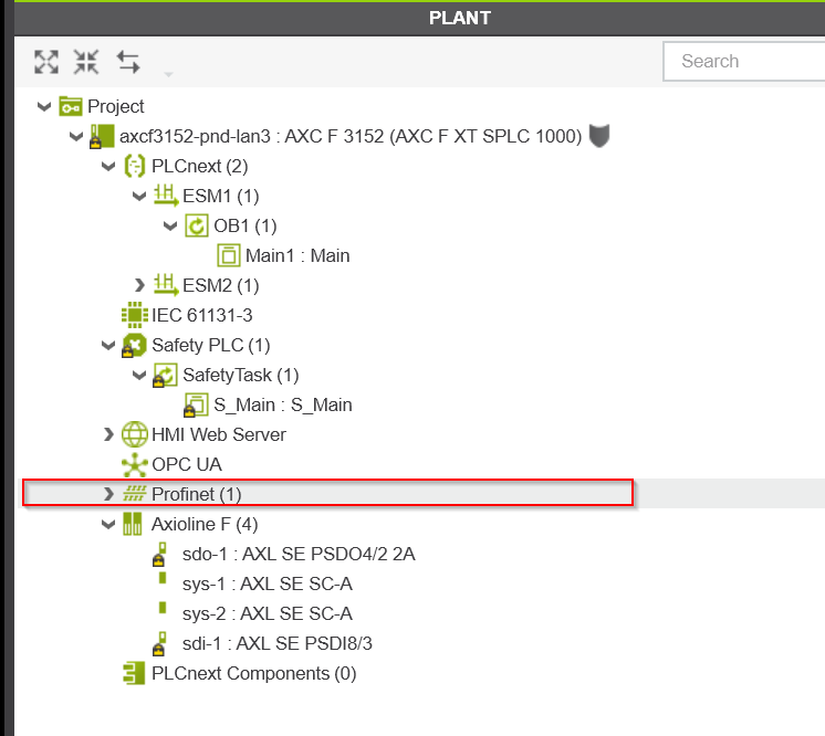
Go to the Update tasks section.
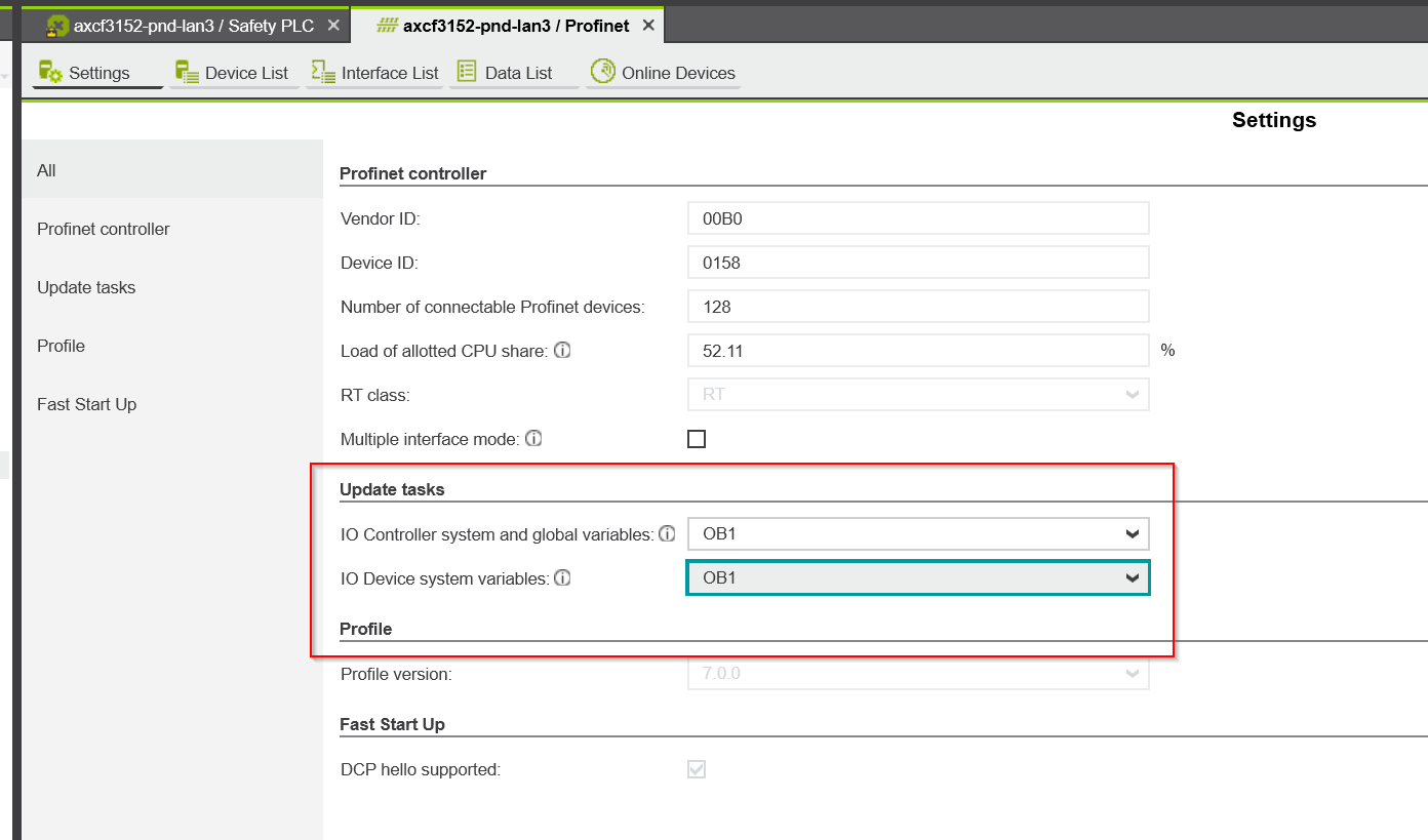
If SafetyProxyTask is set in Update tasks, TUPD AXIO PLCnext = TZSPLC.
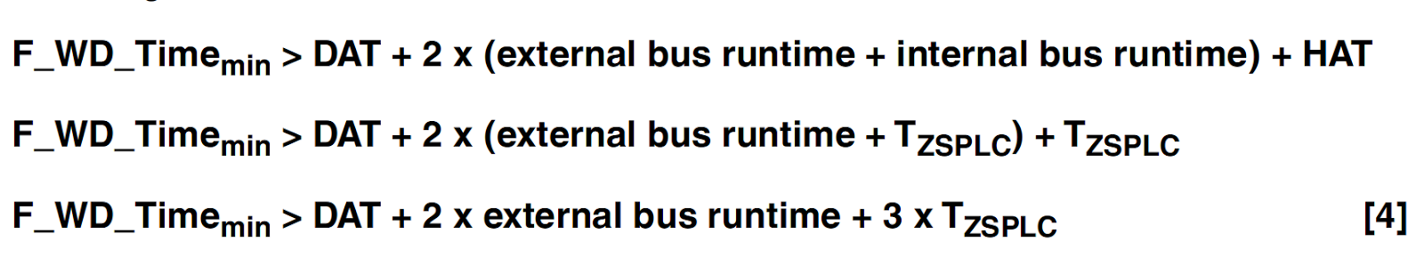
HAT
The HAT Cycle Time for SPLC 1000 is the F-Host Acknowledge Time, and to obtain this time, the Runtime Time of the safety program must be calculated first.
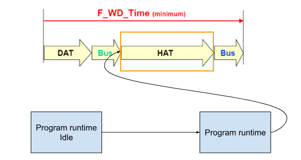
When using SPLC 1000, the program runtime can be calculated first as an ideal component and then by the number of F-Devices used in the application and the number of instances of safety-related Function Block used. The number of F-Devices used in the application and the number of instances of safety-related Function Block used can be calculated.
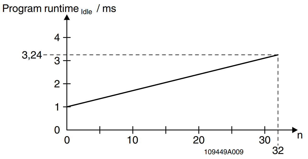
Program runtime Idle
First, let’s find the runtime without safety-related programs: the following formula is given by Manaul in SPLC1000. n is the number of F-Devices, which is 0 for Idle (each time an F-Device is used, Program runtimeIdle is 70 µs extended). n is the number of F-Devices.

So Program runtime (Idle) will be 1 ms. This is a Graph of Program Runtime (Idle) and F-Devices.
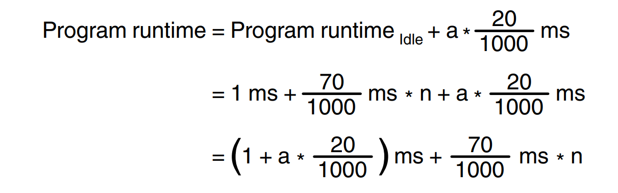
Program runtime
The actual Program Runtime time is dependent on the number of F-Devices used in the application, but as mentioned at the beginning, it is also affected by the Instances of the Safety Function Block used in the safety program (for each Safety Function Block Instance used in a safety-related program, the program runtime is extended by an average of 20µs). (For each Safety Function Block Instance used in a safety-related program, the program execution time is extended by an average of 20µs).
The program execution time is extended by an average of 20µs for each Safety Function Block Instance used in the safety-related program.
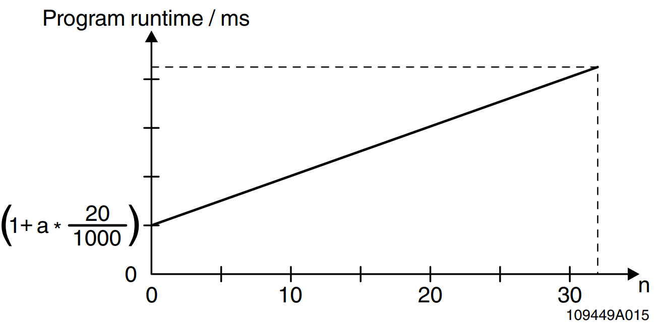
This is a Graph of the number of Program Runtime and F-Devices used and the Instance of the Safety Function Block used for the safety program.
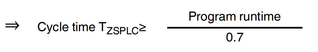
Reference from SPLC1000 Manual, the Program Runtime value for SPLC 1000 must follow the following ratio to the Cycle Time for SPLC 1000 TZSPLC.
That is, Program Runtime divided by Cycle Time must be less than 0.7.
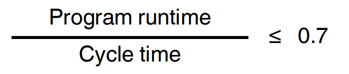
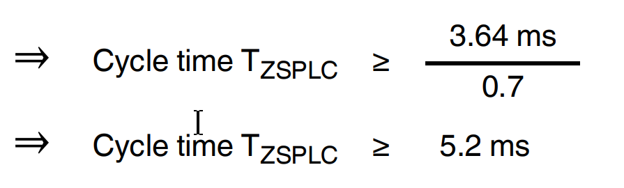
So, in fact, the SPLC 1000 cycle time TZSPLC setting can be obtained and set by dividing Program Runtime by 0.7.
Example calculation
In this example, with 32 F-Devices (n=32) and 20 safety-related Function Blocks (a = 20), the program execution time is as follows
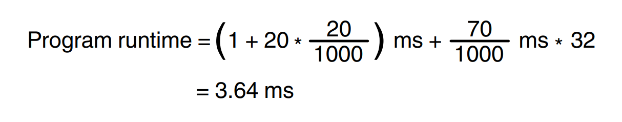
So, the User must set the Cycle time to 6 ms at a minimum.
Commissioning
During the commissioning phase, the values set in the planning phase are verified online in PLCnext Engineer for program runtime and cycle time. For the actual verification, two system variables displayed in the PLCnext Engineer software are used.
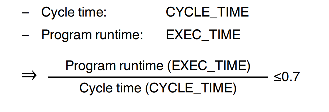
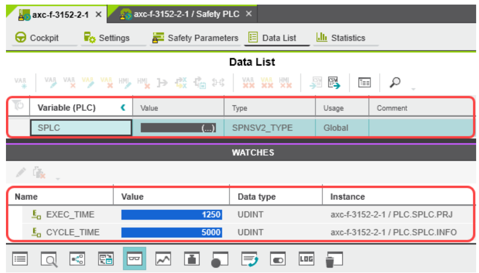
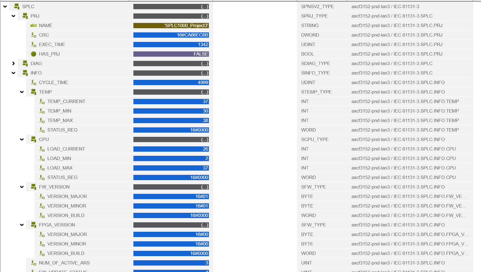
In PLCNEXT Engineering, when SPLC1000 is built in a project, there is a variable named SPLC, in which EXEC_TIME (current cycle time) and CYCLE_TIME (set cycle time) are displayed.
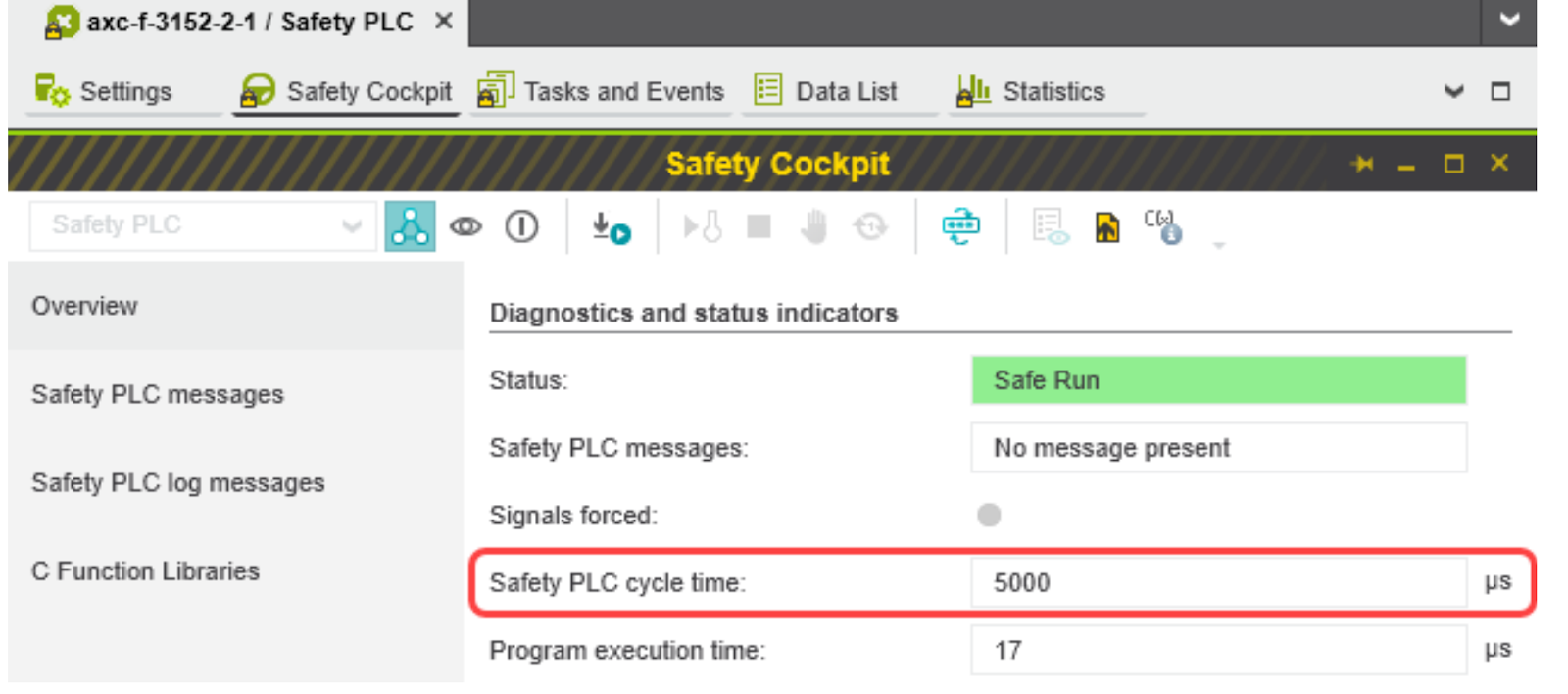
The SPLC 1000 cycle time is also displayed in the “Safety Cockpit”:
Equation Summary
Let’s summarize the calculation formula again: The minimum value of F_WD_Time that can be set by PLCNEXT Engineering can be obtained by the following formula, but in fact, depending on the Configuration, the BUS may CASE whether F-HOST is communicated via Profinet or internal CASE whether the BUS communicates via Profinet or internal BUS.
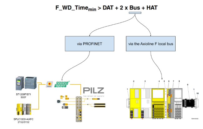
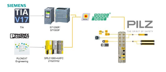
Case1 Communication between F-Host and F-Device via PROFINET
When the SPLC 1000 F-Host communicates with the F-Device via PROFINET,
The F-Device communicates (e.g. via PROFINET bus coupler) with the SPLC 1000 F-Host installed on the left side of the PLCnext Control Device (here AXC F 3152).
Due to Manual, SPLC 1000 cycles and PROFINET cycles are executed asynchronously to each other, so SPLC 1000 cycles must be twice the minimum F_WD_Time.
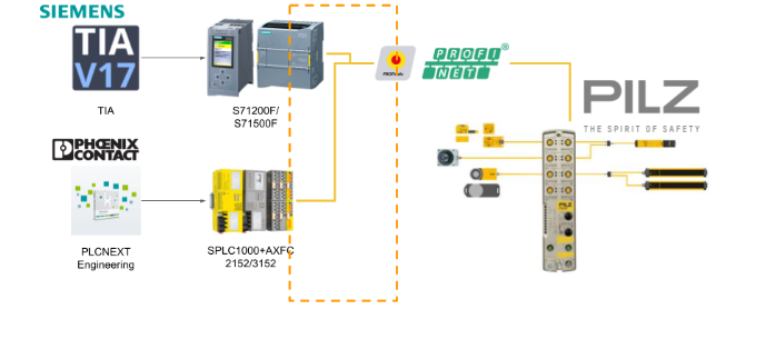
Case 2 Communication between F-Host and F-Device via the Axioline F local bus
When the F-Host of the SPLC 1000 communicates with the F-Device of the Axioline F, it is bussed through the Axioline local bus. In this case, the F-Device is placed to the right of the PLCnext Control device used (in this case, AXC F 2152).
The internal bus runtime for this configuration is the sum of the CPU internal update time TUPD AXIO PLCnext or TZSPLC (HAT).

Since TSZPLC=TUDP AXIO PLCNEXT, the calculation formula ends like this;

Example
Now let’s actually calculate the time for Watchdog, etc. The minimum F_WD_Time OUT for communication with F-Device AXL F PSDO8/3 1F corresponds to Case 1 Communication The minimum F_WD_Time OUT for communication between F-Host and F-Device via PROFINET is the same as Case 1 Communication between F-Host and F-Device via PROFINET.
Parameterize and check/verify its monitoring/watchdog time (F_WD_Time IN/F_WD_Time OUT) within the determined upper and lower limits. It is important that each safety function can be executed with the defined monitoring/watchdog time.
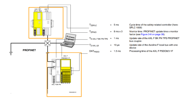
Case1:TZPNIO=8ms x 3
In the actual calculation, several factors need to be taken into consideration.
- TZSPLC=5ms, period of SPLC1000
- TZPNIO=8ms x 3, Update time set by PLCNEXT software x monitor factor
- TD AXL F BK PN TPS=1ms, Update Rate for TD AXL F BK PN TPS
- TZ AXL LB=10us, 1 Axioline F localbus Update rate
- DATPASDO=1.5ms, AXL F BK PN TPS processing time
In practice, the formula can be formulated like this.
TBus = SPLC1000 period + Update time x monitor factor set by PLCNEXT software + 2xTZ AXL LB.
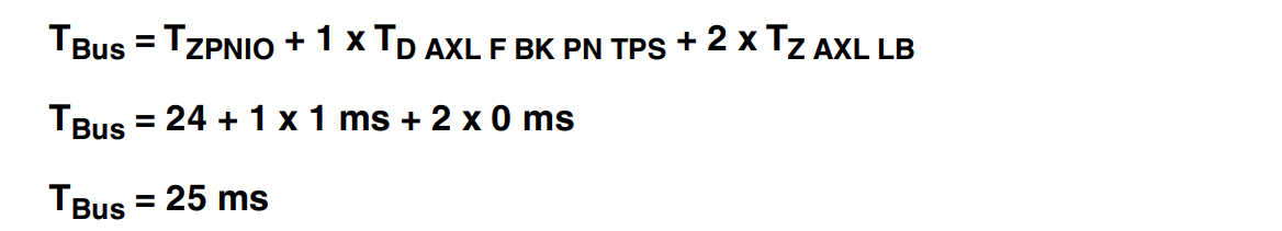
In the example configuration of the AXL F BK PN TPS and the Axioline F output module (AXL F PSDO8/3 1F), the following equation is obtained
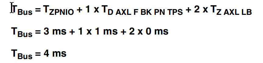
Case2:TZPNIO=1ms x 3
In this example we will try to find the F_WD_Time setting from the bus cycle and transfer time, in particular here the PROFINET update time and the monitor time.
Now let us calculate the minimum possible F_WD_Time OUT if the PROFINET update time is kept at 1 ms by “Reduction ratio=1” and the monitor factor is kept at 3.
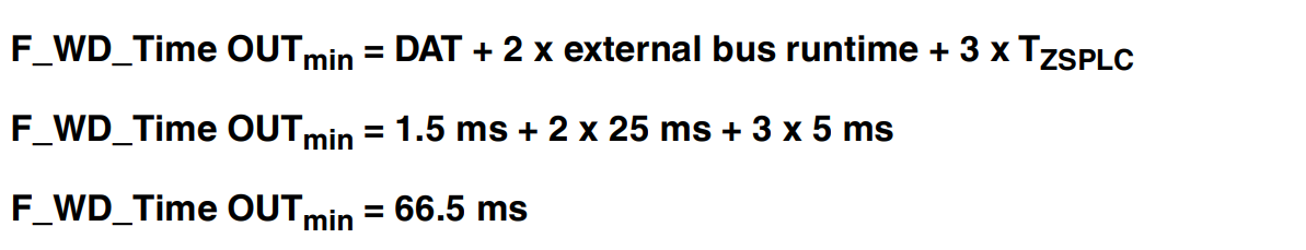
Next, F_WD_Time Outmin is calculated.

Having just calculated the upper and lower limits of F_WD_Time IN/F_WD_Time OUT, the F_WD_Time IN/F_WD_Time OUT watchdog times must be parameterized within these ranges for the safety functions to be implemented in the application.

The 200ms here is the Upper Limit of the Safety function.

This one was calculated earlier.

Let’s assume 50 ms here.

F_WD_TIMEOut will be roughly 50ms.

F_WD_TimeIn will be 100ms. Setting this Factor to 2 will also reduce the impact on the overall system if Profinet’s Update time is slightly slower in the future.

Finally from this you can set the watchdog time to <= 200ms.

Implementation
Pilz Side
Wiring
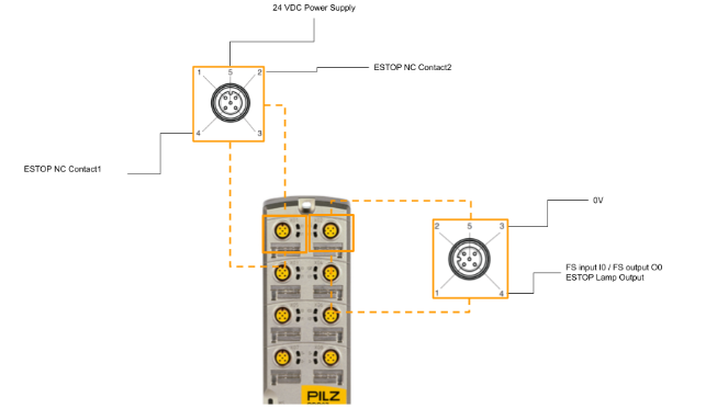
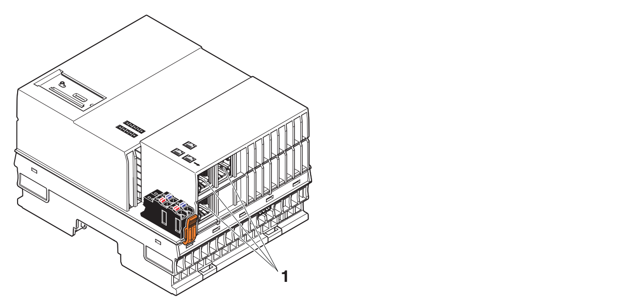
Here is the wiring this time, PortX1 is connected to the 1:2 ESTOP NC contact, and Pin 4 of PortX02 is the ESTOP lamp output.
Mapping
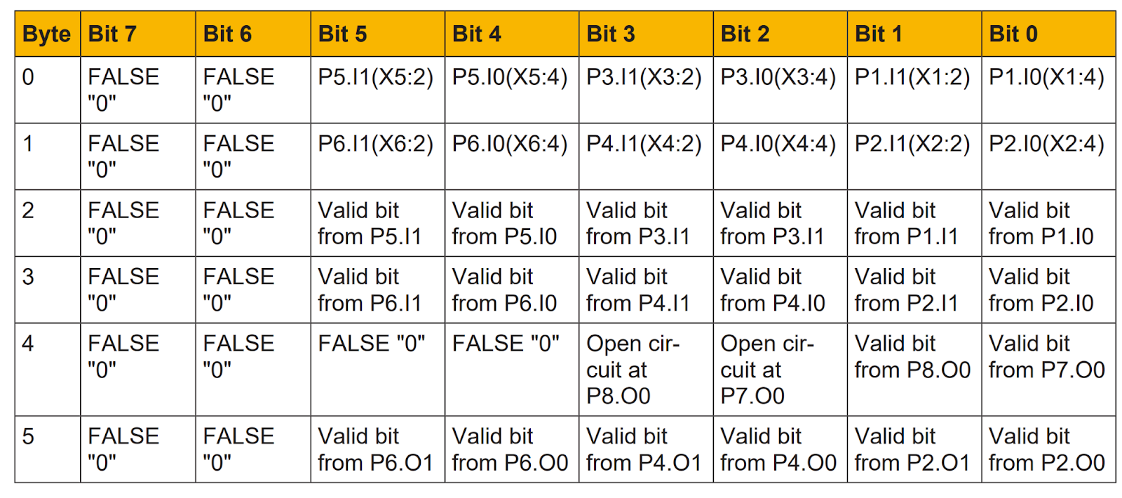
FS input data in the process image of inputs (6 Bytes)
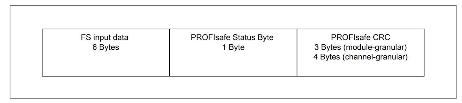
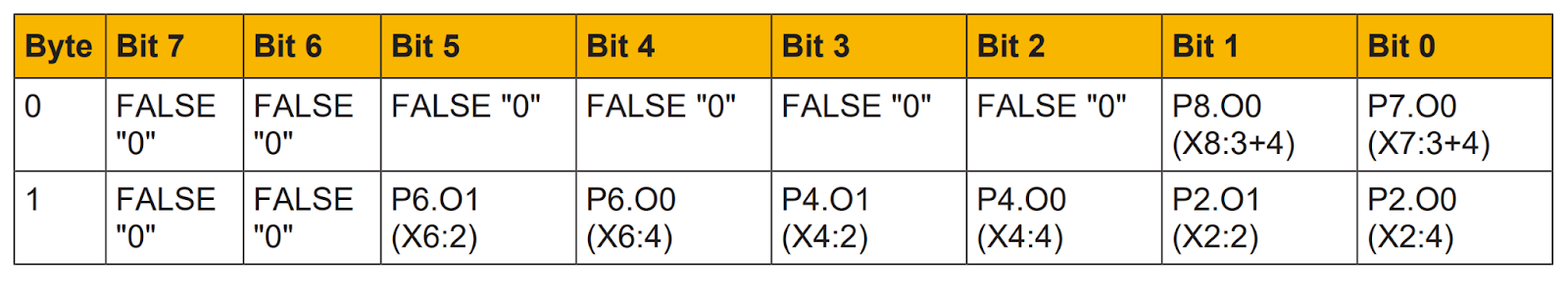
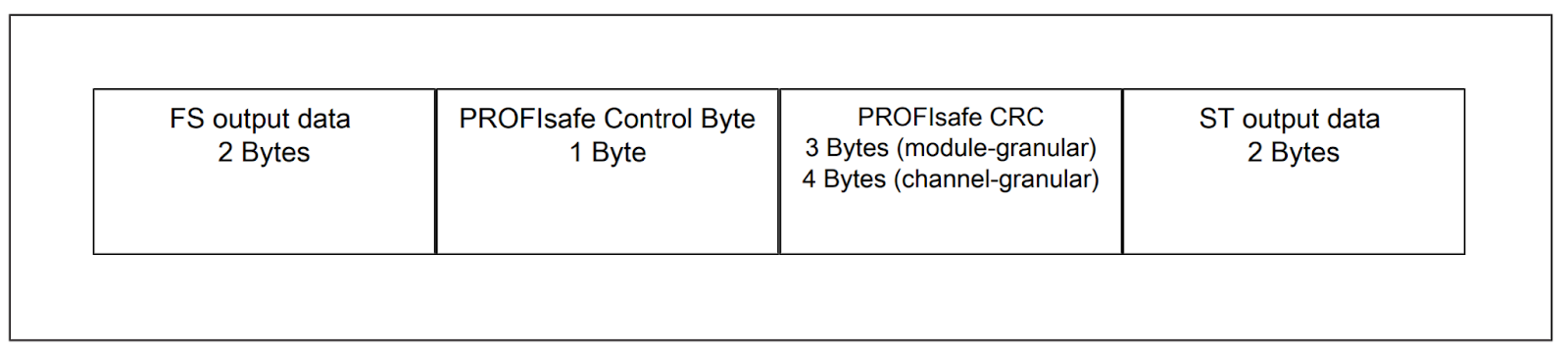
FS output data in the process image of outputs (2 Bytes)
PASConfig 5.1.1
Download Tools
You can download the PasConfig tool from the link below.
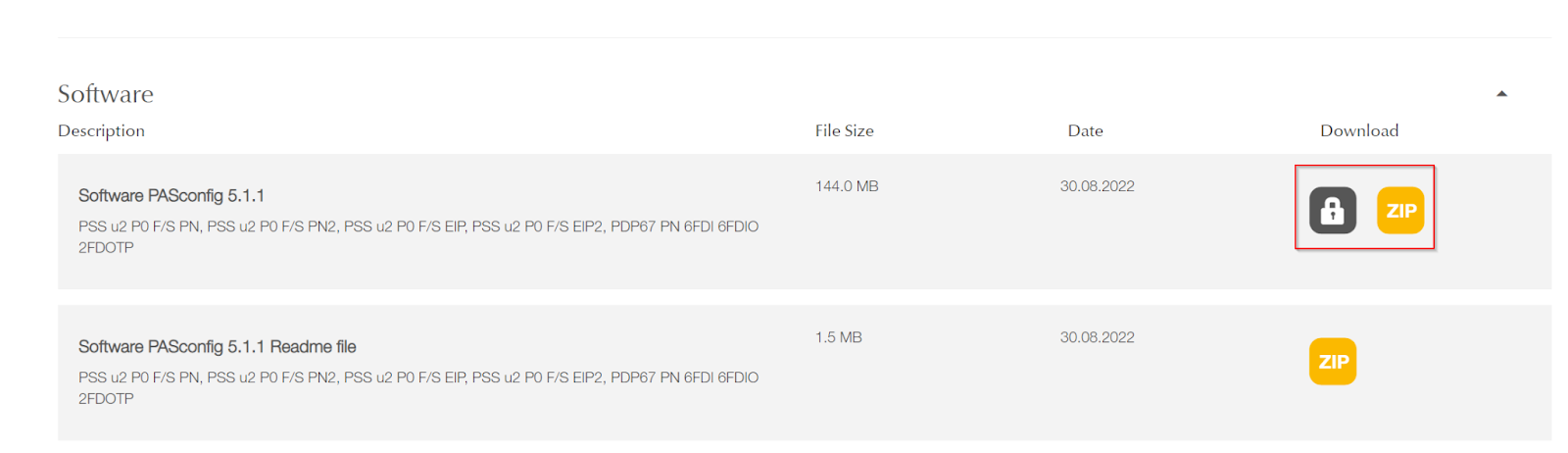
A ZIP File like this was download.
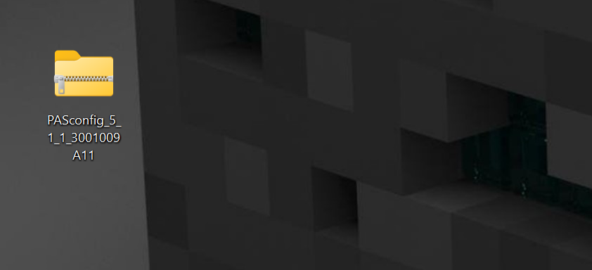
Installation
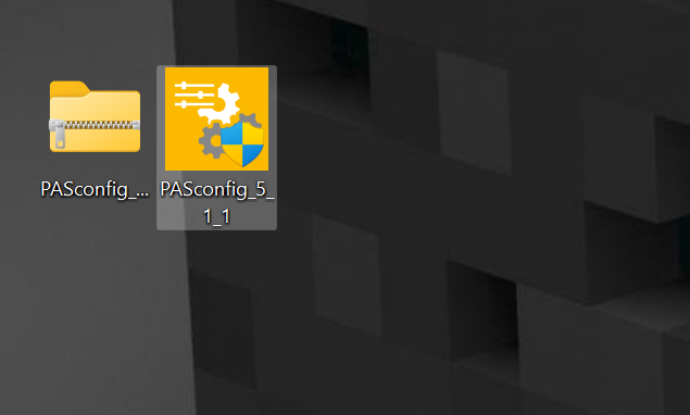
Unzip the Pasconifg ZIP from earlier and start PASconfig_5_1_1.
just a second..
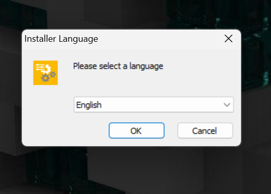
Set the installation language. In this case, set it to English.
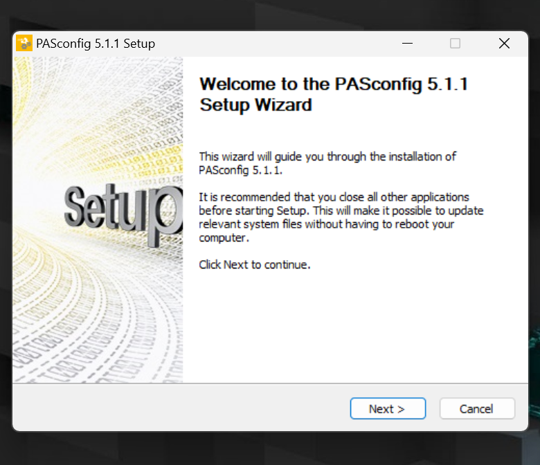
Proceed with Next>.
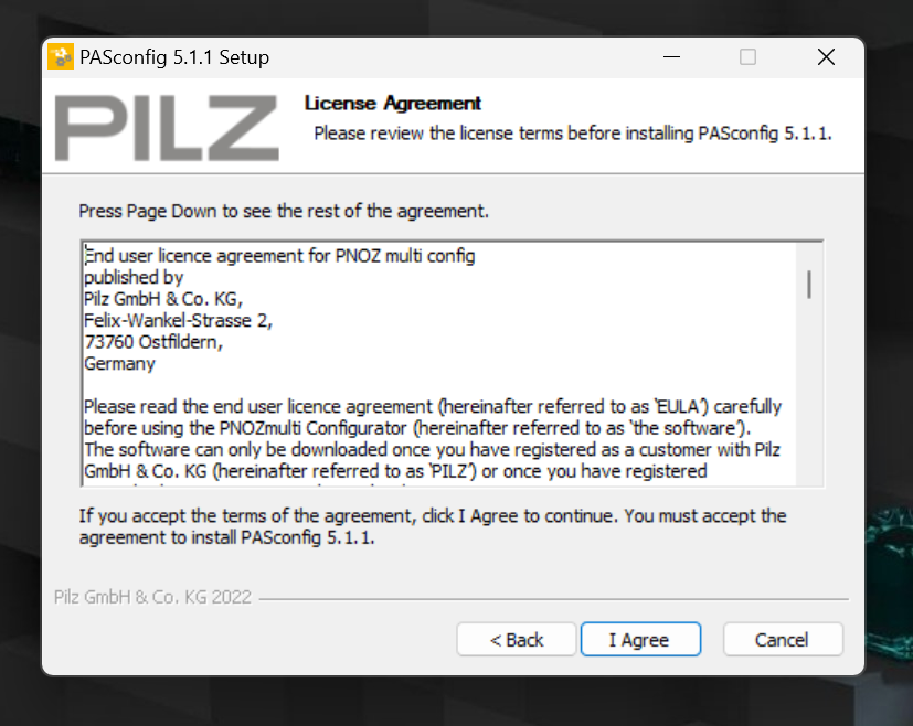
Click “I Agree” to accept the license and proceed
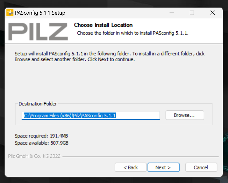
Set the installation location and proceed with Next>.
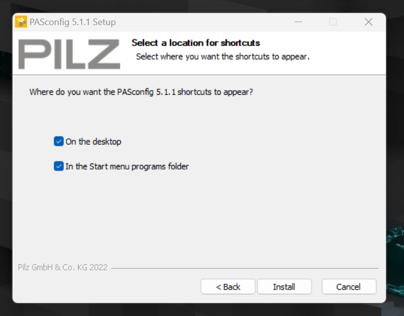
Enter a Checkbox to create Shortcuts, etc., and proceed with Install.
just a second..
Done!
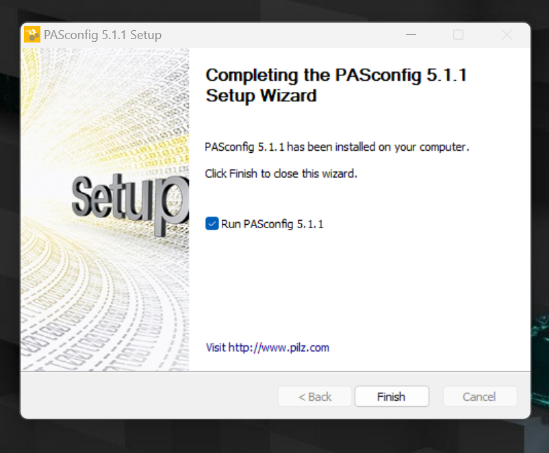
PASconfig software has been started.
Add New Project
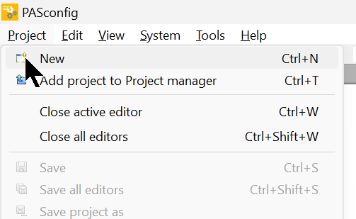
Create a new project with Project>New.
Project Type
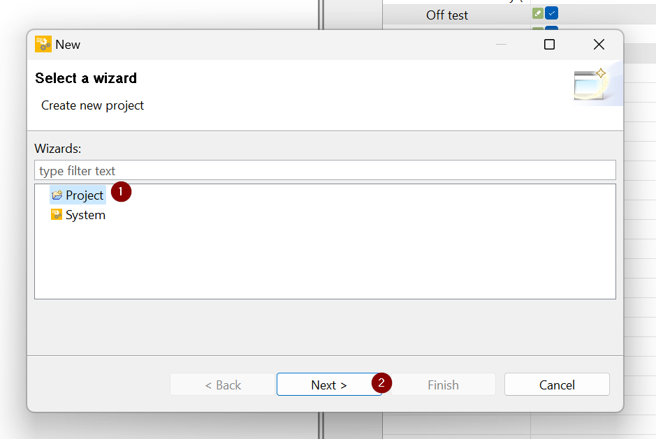
A Wizard is provided in Pasconifg to allow Step By Step project creation.
First, select the Project type.
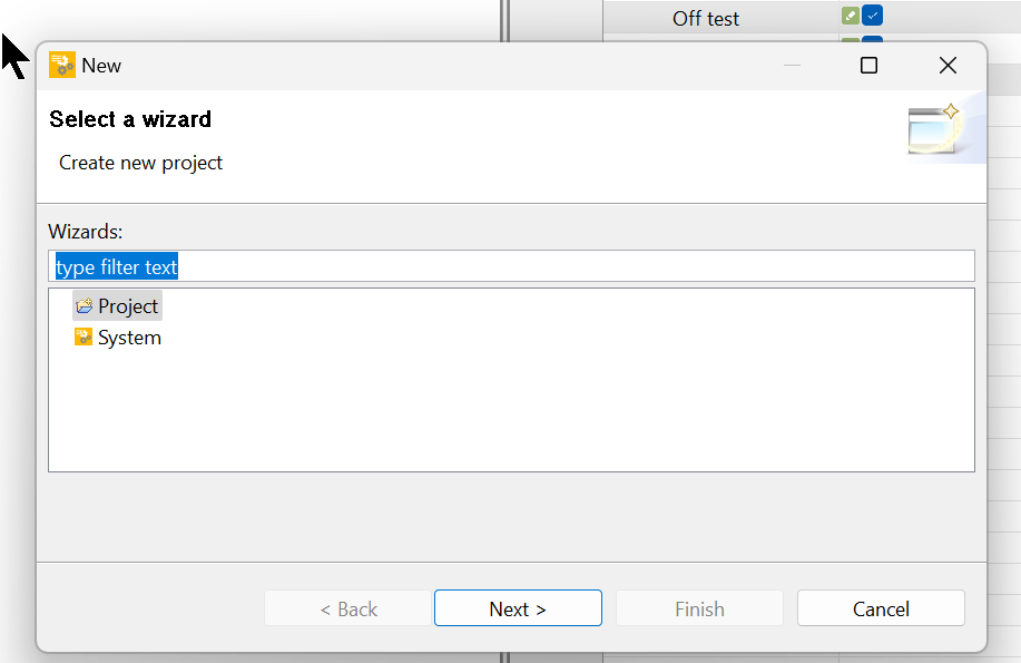
Select Project and press Next> to proceed.
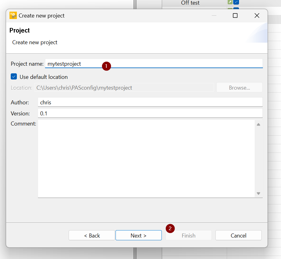
Project Info
Next, enter the Project information.
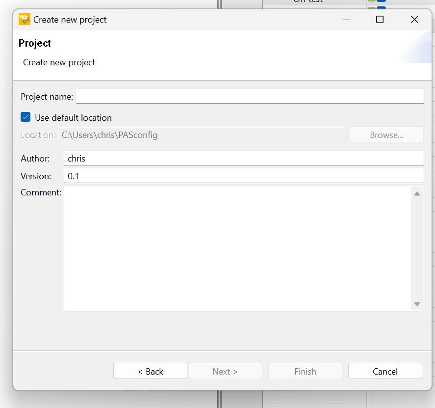
Enter a project name and press Next> to proceed.
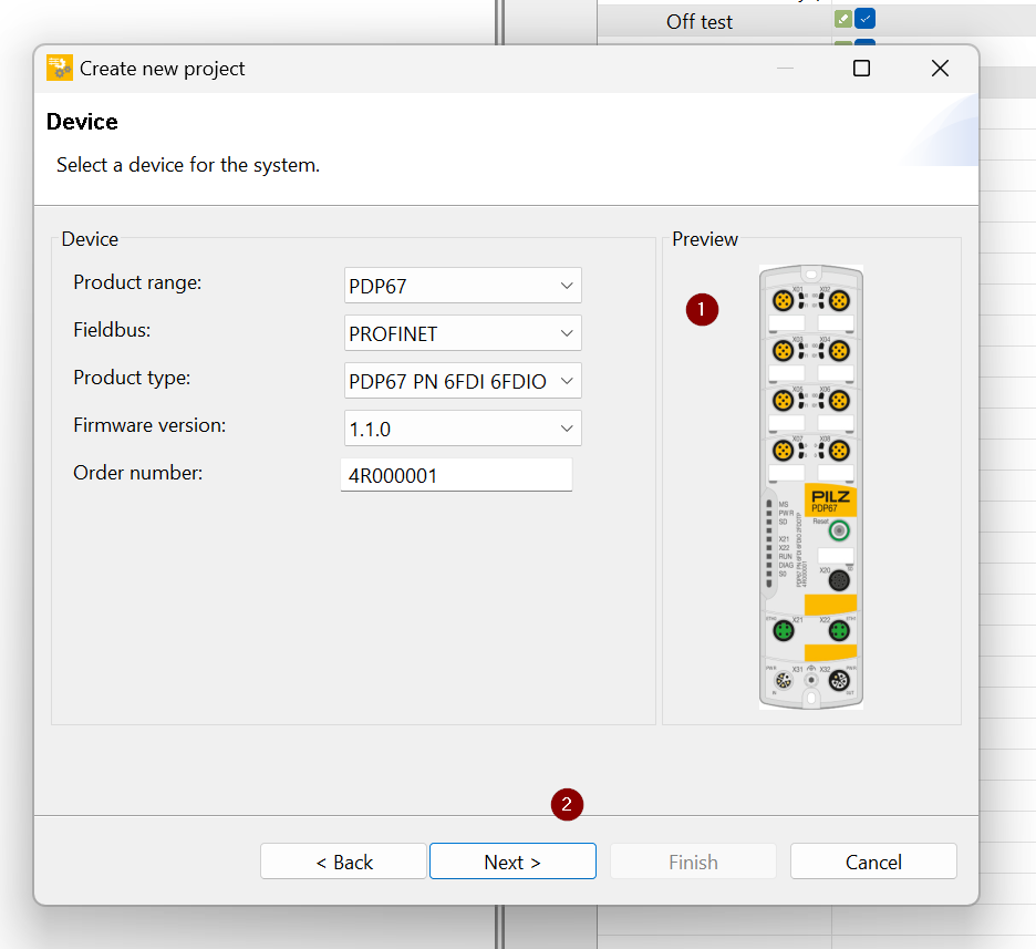
Device Type
Now the device type setting screen appears.
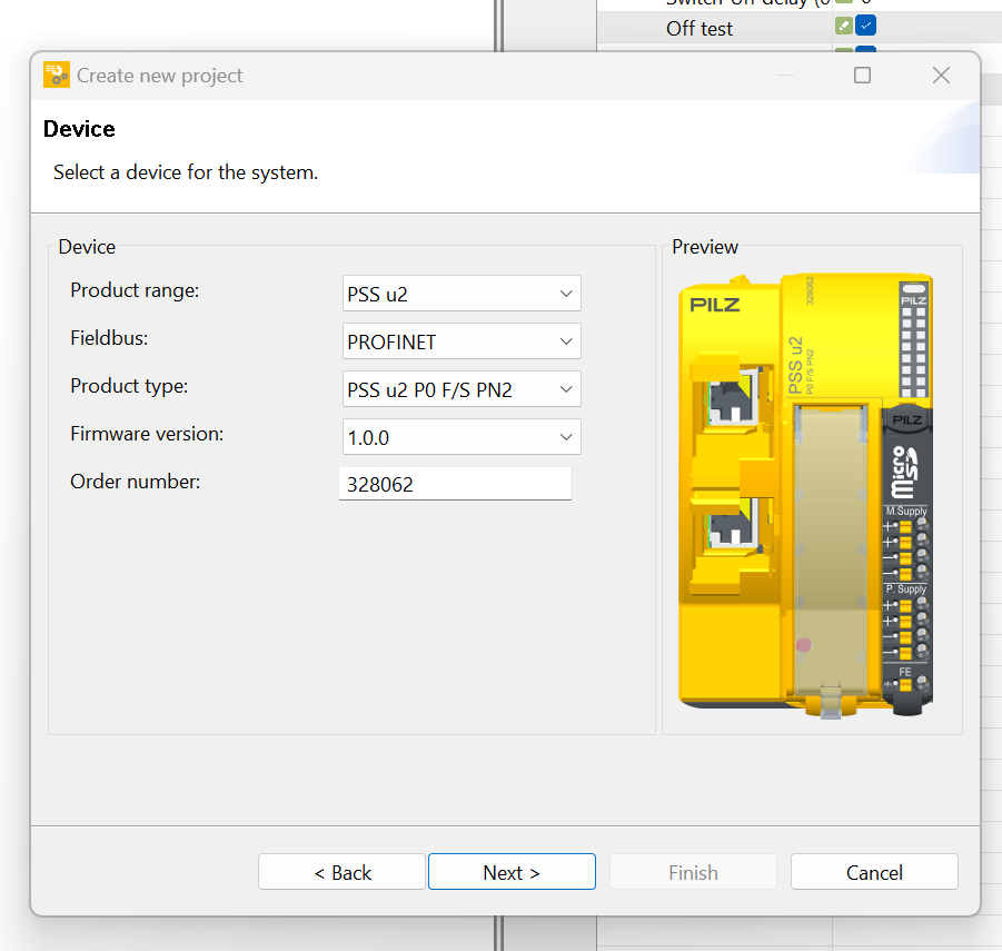
Set the Product range to PDP67 from the Drop-List.
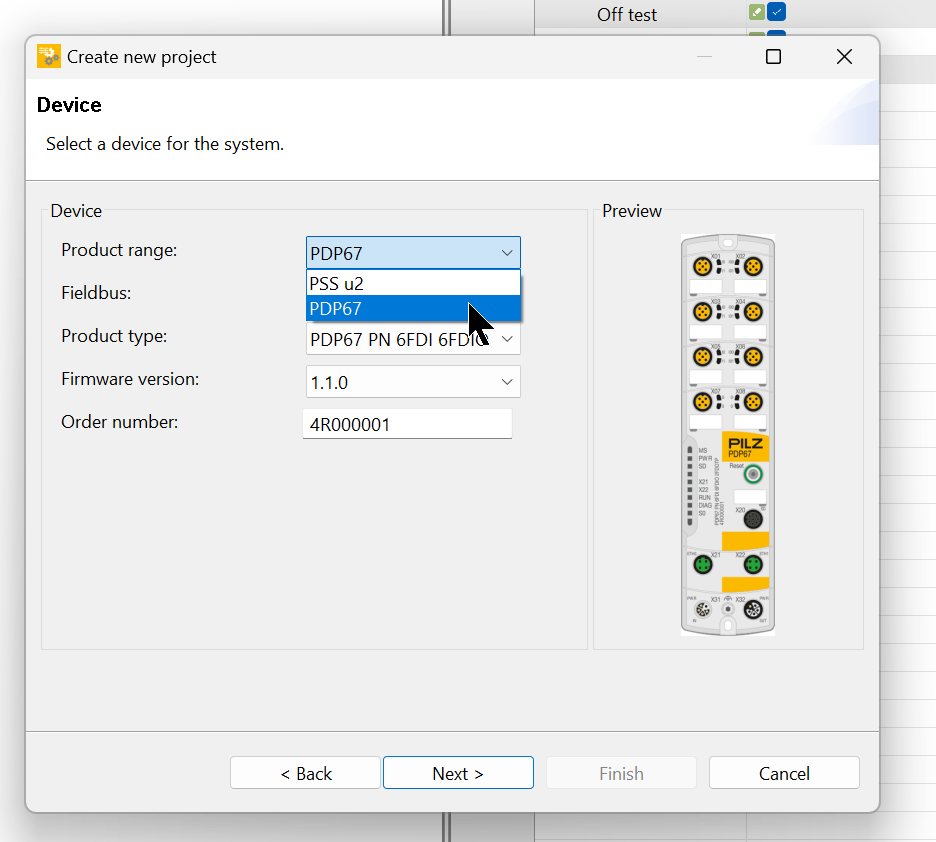
The Preview screen will change to a picture of the PDP67 device and proceed with Next>.
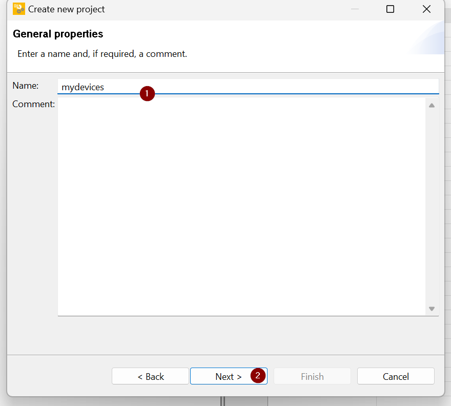
Device Name
Enter a device name. This setting is not related to the Device name in Profinet, so you can set a name that is easy to change.
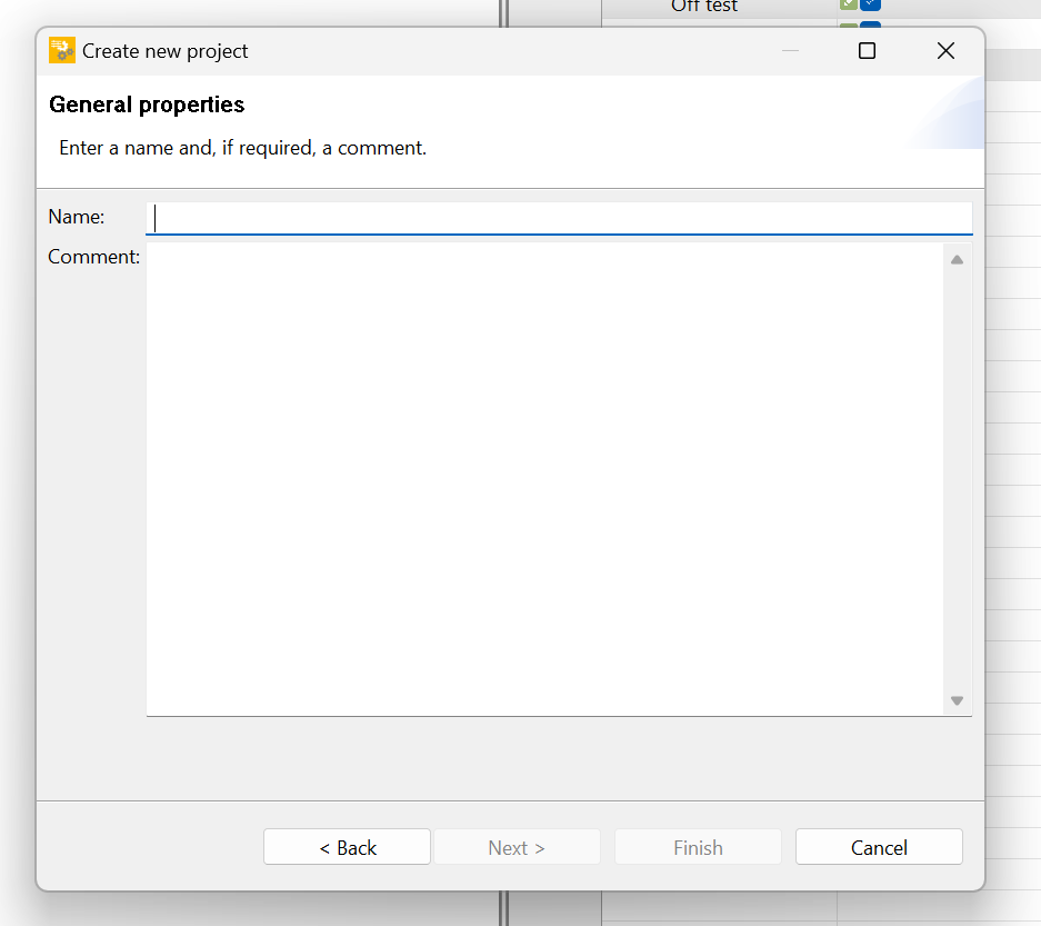
This time, enter mydevices and press Next> to proceed.
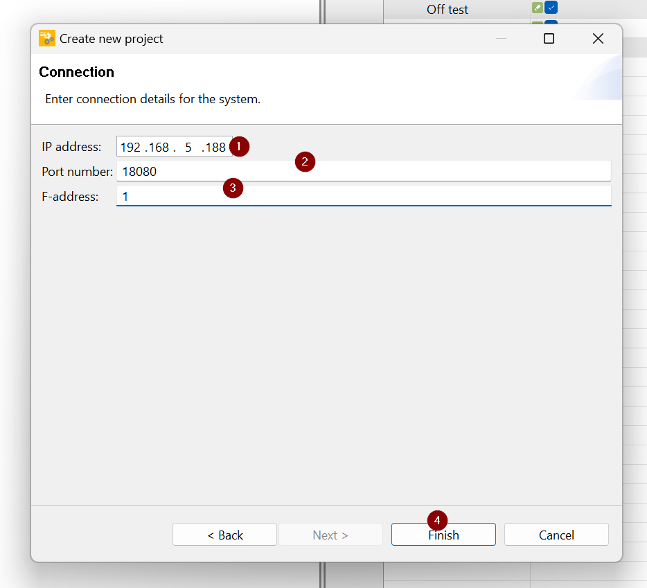
Connection
The device connection settings screen appears.
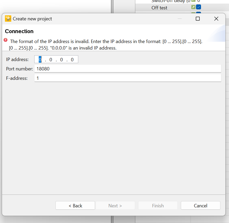
Enter the IP address of the device; if the Ip address of PDP67 is correct, the F-Address can be uploaded later.
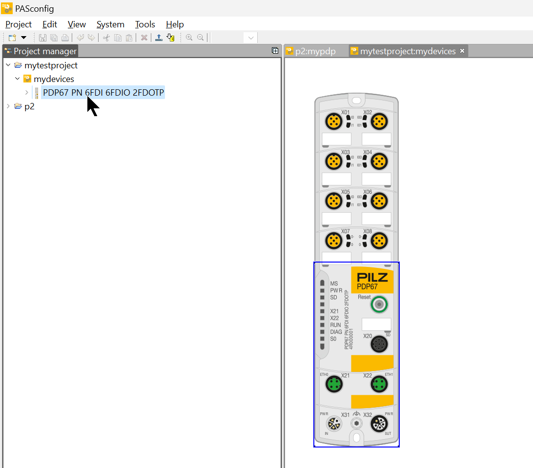
Result
Done!A project for PDP67 has been created.
Get F Address
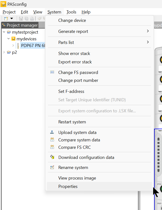
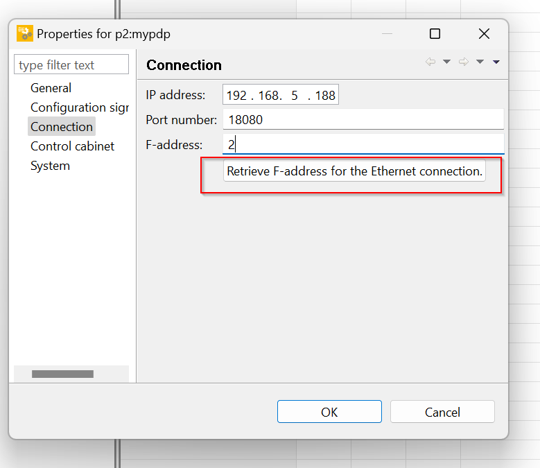
Click System>Properties to get the F-Address of the current PDP67.
Opening the Connection tab brings up the Pasconfig and PDP67 connection parameter screen.
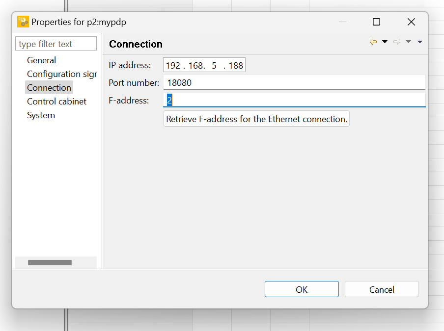
You can get the F-Address of PDP67 via Ethernet by clicking on the button “Retriveve F-address for the Ethernet connection”.
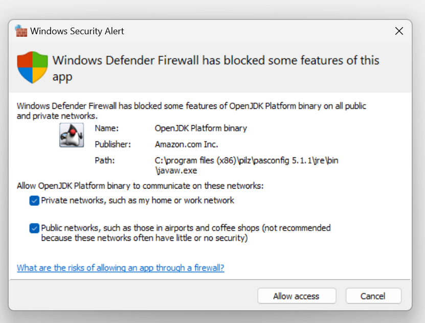
If you are using Pasconfig for the first time, the Windows Security Settings screen will appear and you should proceed with Allow access.
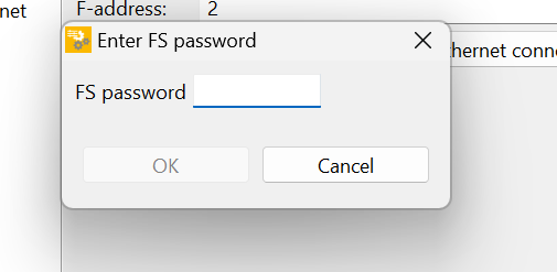
If you successfully connect to PDP67, you will be prompted for FS Password.
Default is pssu.
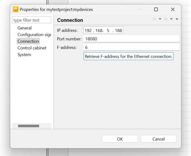
Done!F-Address now obtained for PDP67.
Set F Address
次はPDP67のF Address設定方法を説明します。System>Set F-addressをクリックします。
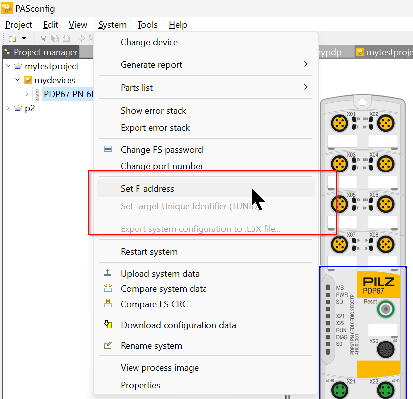
The Set F-addresses screen appears.
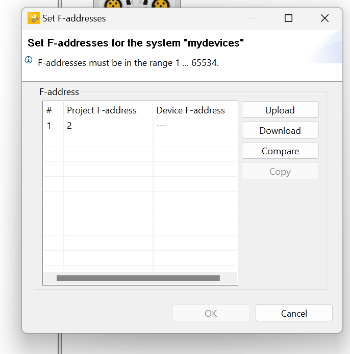
Upload
Use the Upload button to get the F-Address of the current PDP67.
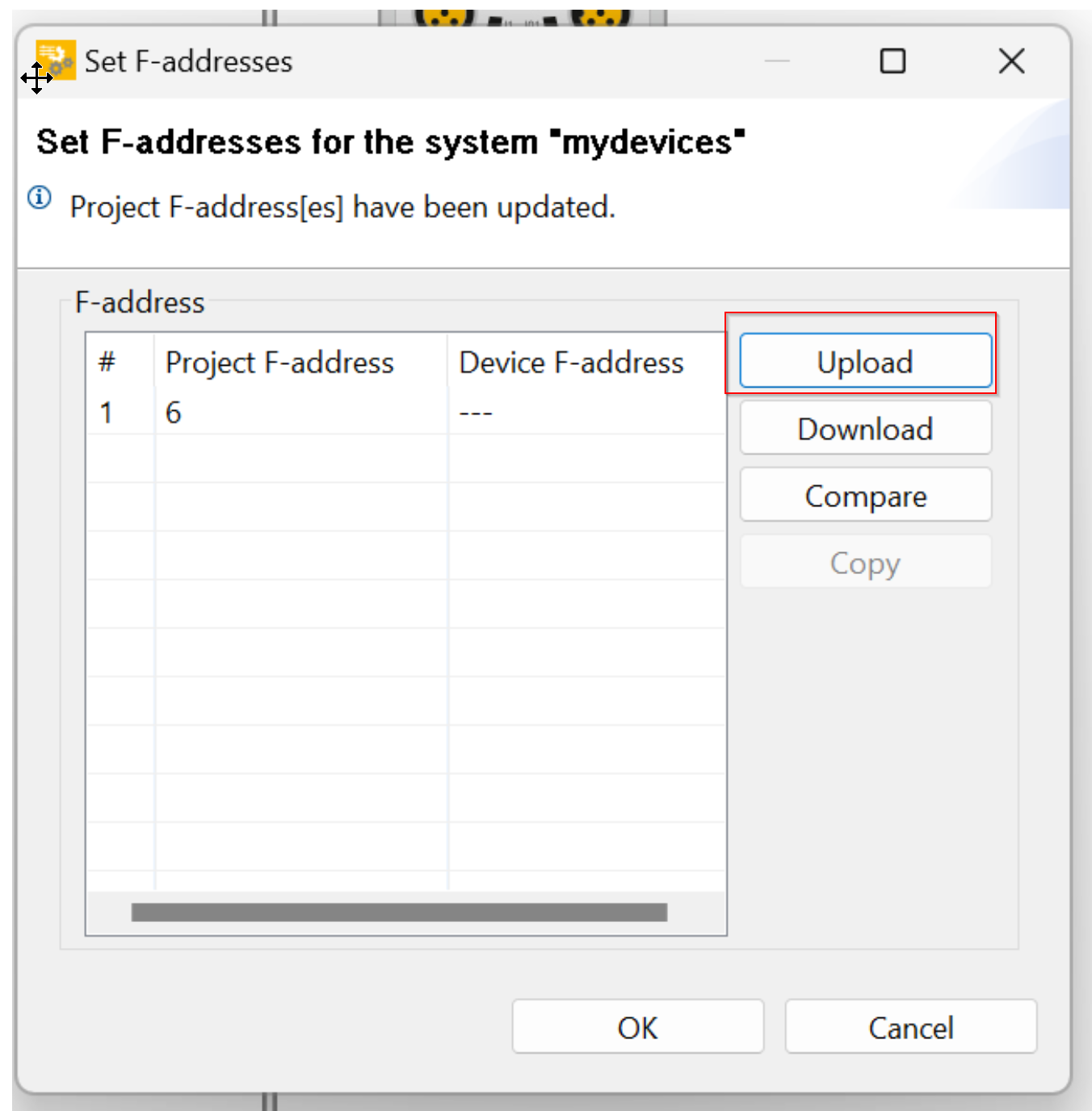
Done!
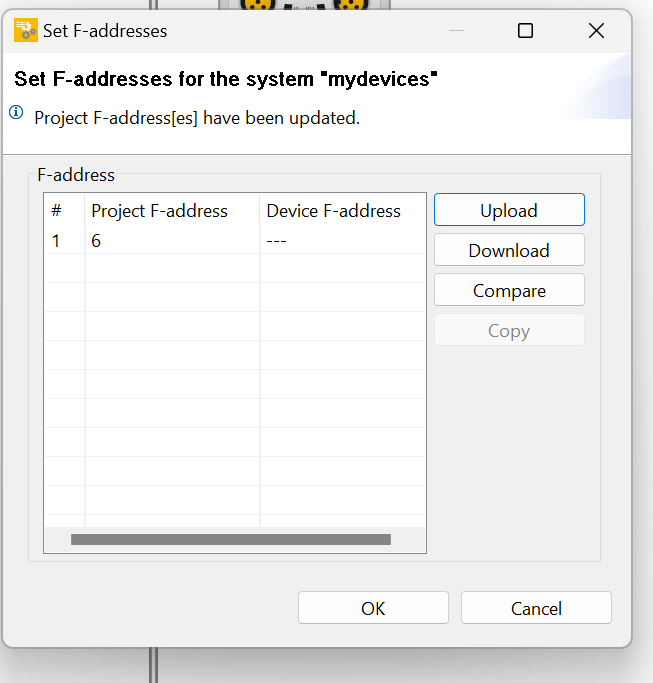
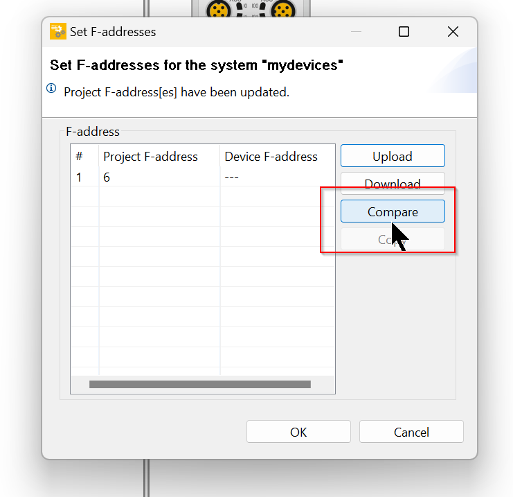
Compare
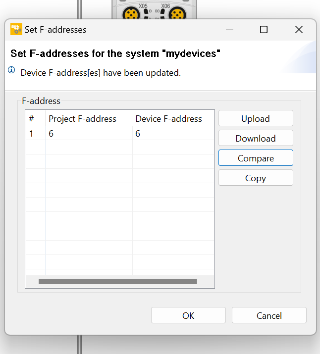
Next, the Compare function allows you to compare the F-Addresses of the Project and the actual PDP67.
Done!The Project F-address on the left is the PDP67 F-address set in the project, and the Device F-address on the right is the F-address of the actual PDP67.
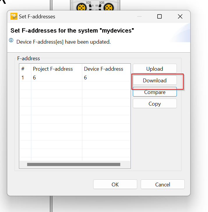
Download
Finally, use the Download button to downlaod the F-address of the project to the actual device.
Configuration
After setting up the F-Address, the next step is to set up the module itself.
Hyriod Ports X02
This Tutorial will set the Hyriod Port of X02 as the FDO, so click on X02 directly from the screen.
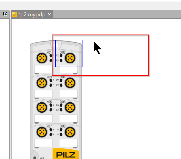
The Properties screen appears on the right.
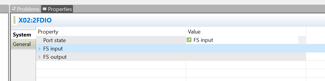
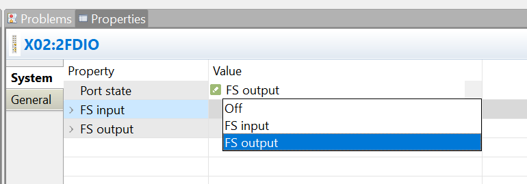
Change the Port State setting to FS Output.
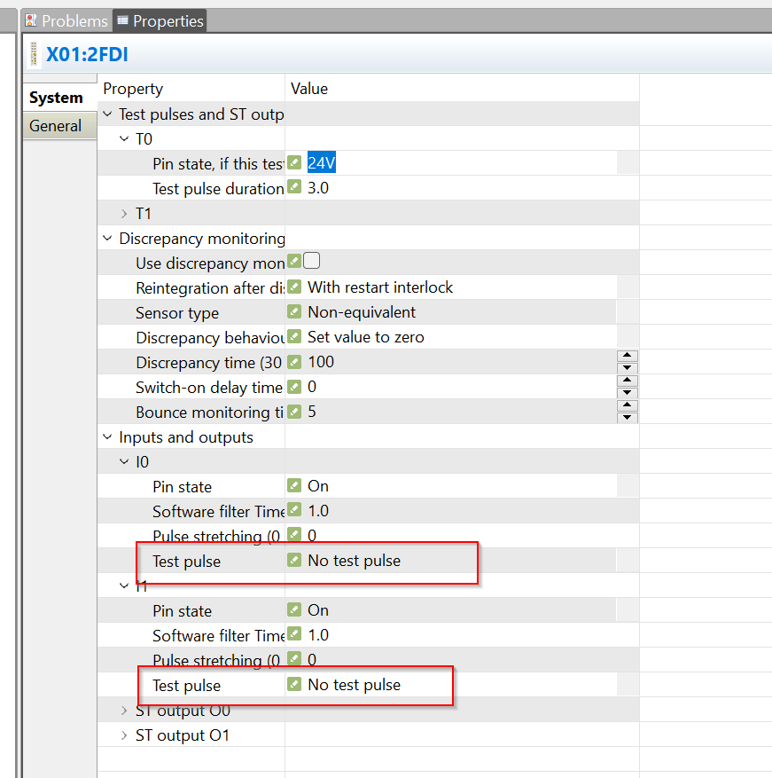
Port X1
Next, configure Port X1.
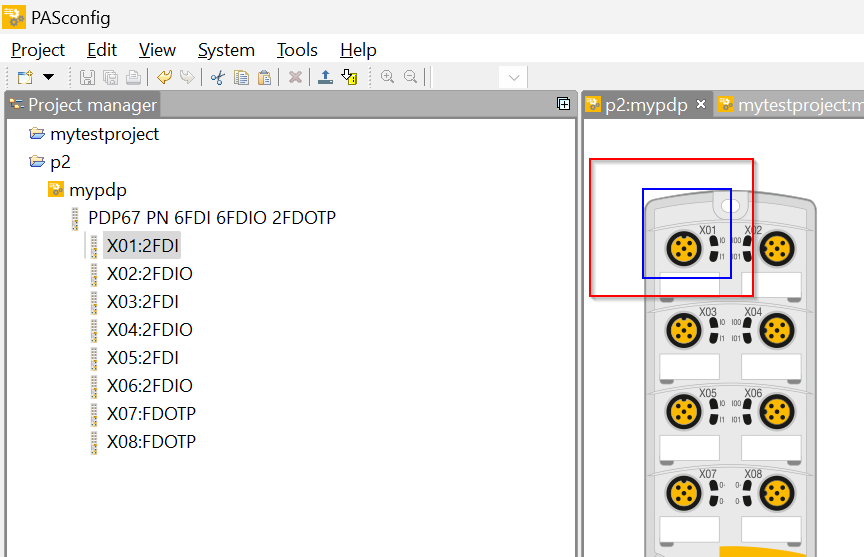
Since we will not use the test pulse function in this article, set “No Test pulse” in System>Inputs and Outputs>Test pulse.
FS 2 pole Output Ports X7 X8
The last step is to set the X07/X08 safety 2Pole output.
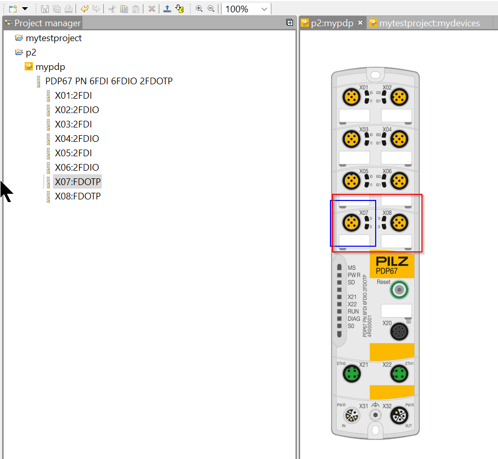
Since X07/X08 will not be used in this article, the Default setting will result in a PDP67 error.
Turning Port State Off disables the corresponding Port.
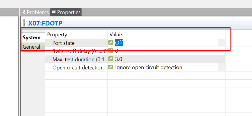
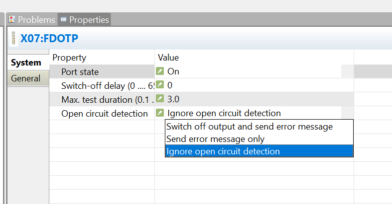
Or, disable open circuit error detection by setting Open circuit detectiion to “Ignore open circuit detection”.
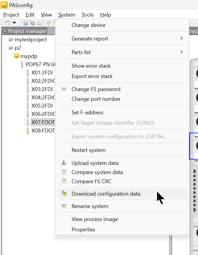
Download Configuration
Finally, download the configuration file to PDP67 by going to System>Download configuration data. Note that once the configuration file has been downloaded to PDP67, Wiretest cannot be used.
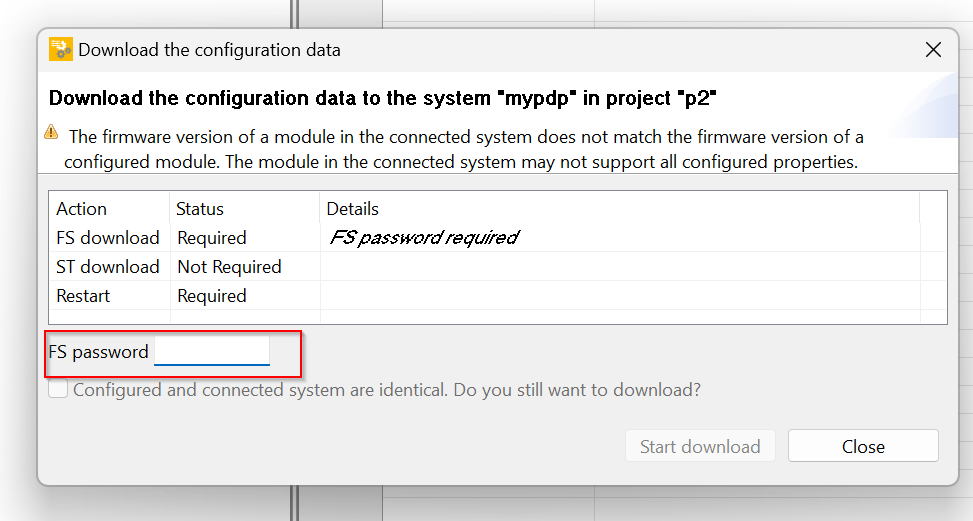
You will be asked to enter a password.
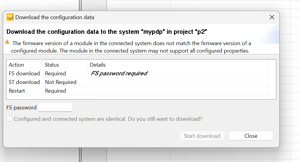
Enter the Password for PDP67 in the FS password field.
Default is pssu
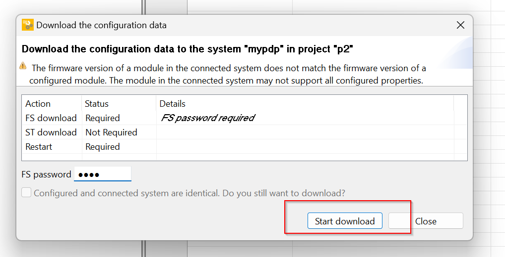
After entering the password, click on Start Download.
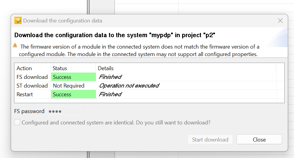
Done!
PLCNEXT Side
Profinet Interface
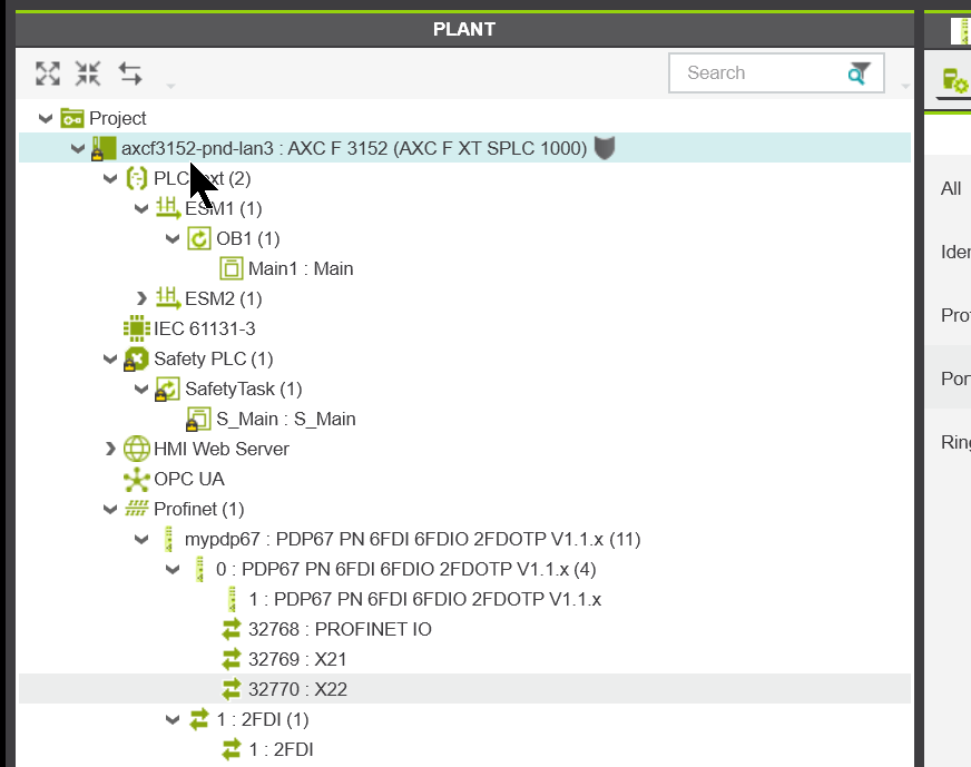
The AXCF3152 used in this project has three Interfaces: X1/X2/X3.
- X1:Etherenet Interface,Default IP=192.168.1.10
- X2:Profinet Controller Interface.Default IP=192.168.2.10
- X3:Profinet Device interface.Default IP=192.168.3.10
So use X2 when connecting to PDP67.
Import GSDML
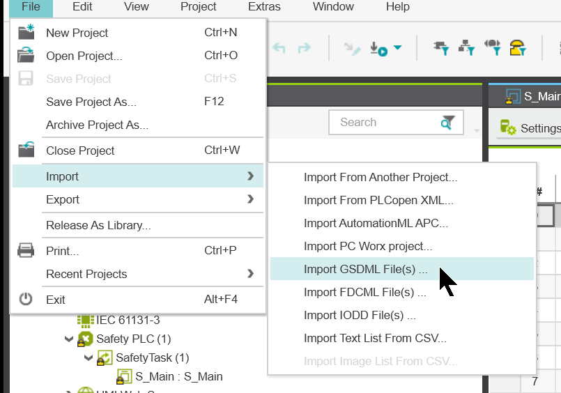
File>Import>Import GSDML File(s) to import GSDML File(s).
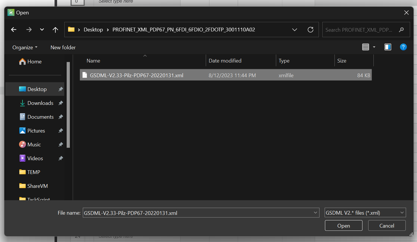
Select the GSDML File you have just downloaded from Pilz HP.
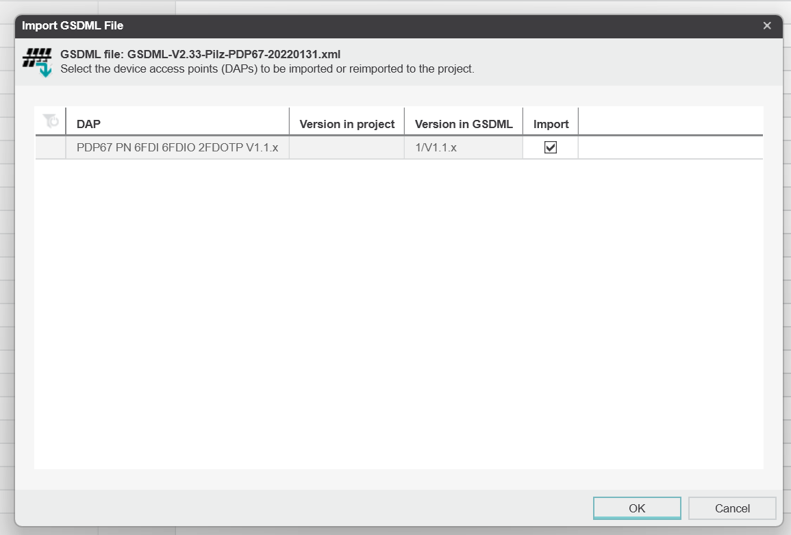
Check the “Import” box and press “Ok” to proceed.
Add Devices
After importing the GSDML File, the next step is to build the Profinet network.
Click on Project>Profinet.
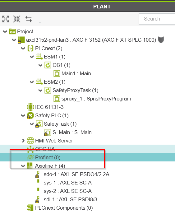
The Profinet build screen has been replaced by the Profinet build screen.
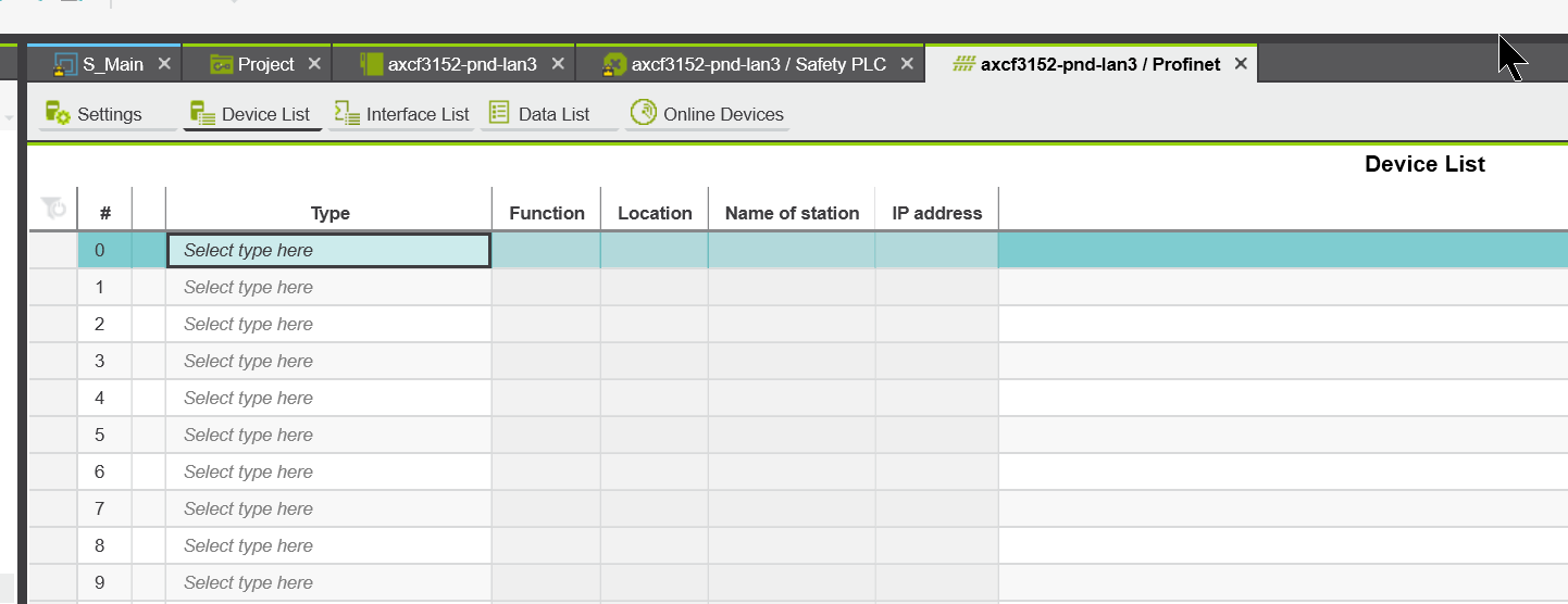
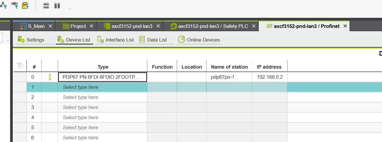
Click on #0 Type Field to add a device.
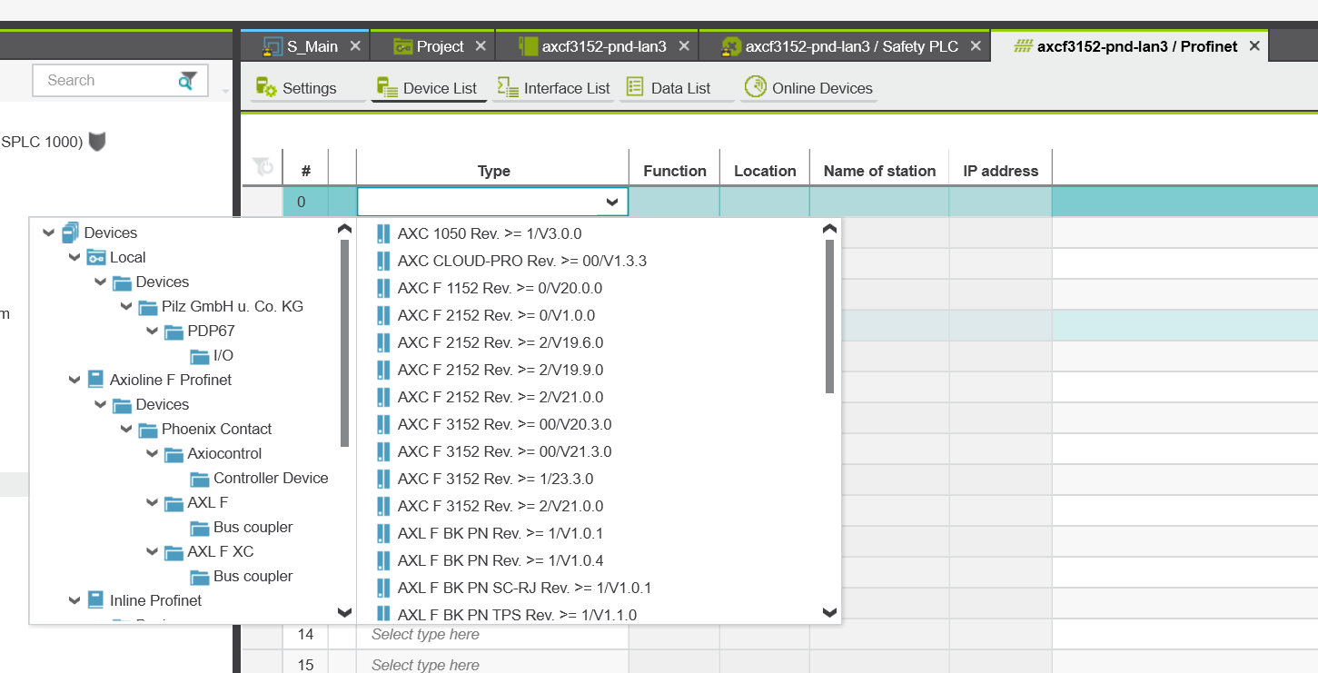
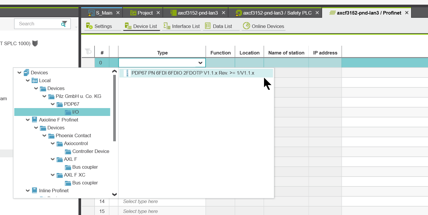
Select PDP67 PN 6F DI 6FDIO 2FDOTP from PDP67>I/O.
Pilz’s PDP67 PN 6F DI 6FDIO 2FDOTP is a Safety device and therefore requires a Safety project Password entry.
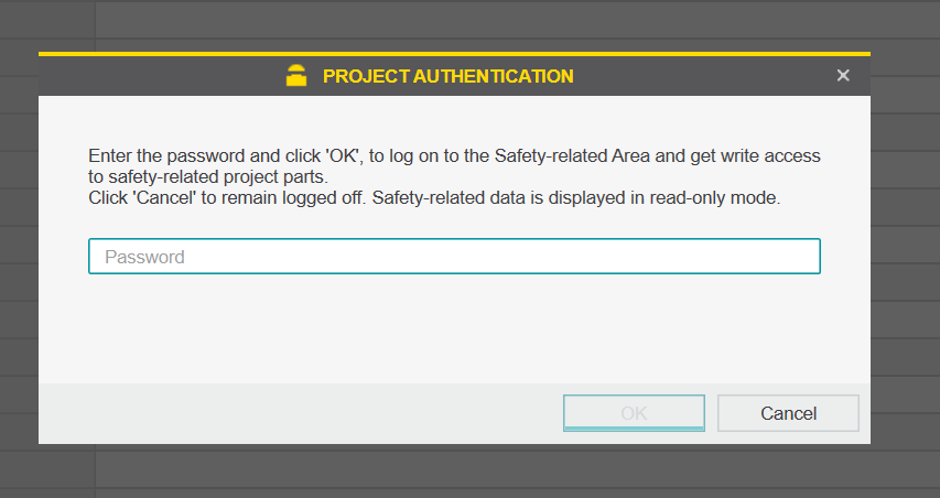
Done!Pilz’s PDP67 PN 6F DI 6FDIO 2FDOTP could be added.
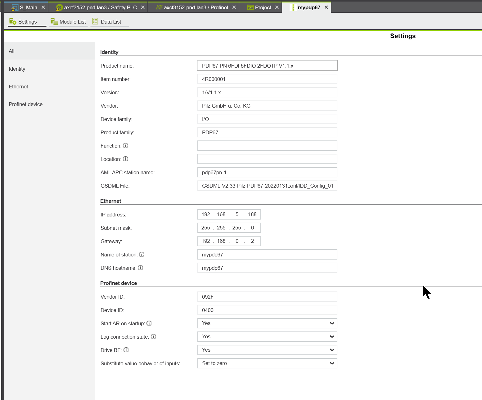
Configure Device Name/IP Address
Set the device name and Ip address in the Name of Station and Ip address fields.
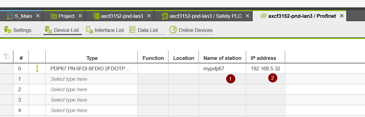
Done!
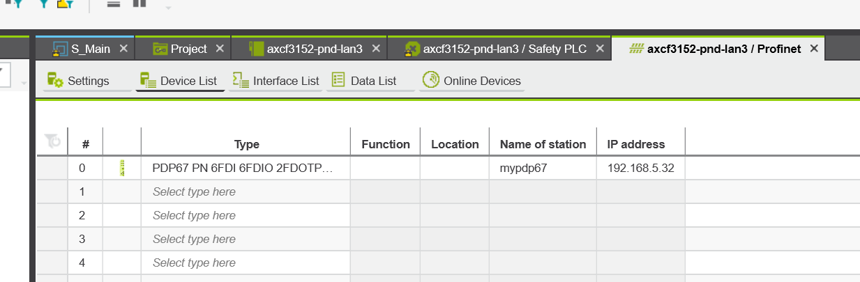
Configure Slot
The next step is to set up the PDP67 PN 6F DI 6FDIO 2FDOTP communication and other settings.
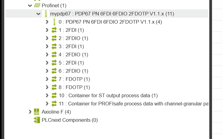
Click on mypdp67 that you just added.
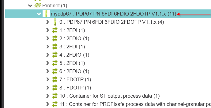
A detailed device configuration screen will appear.
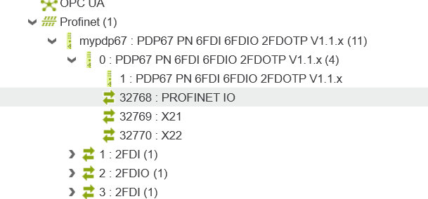
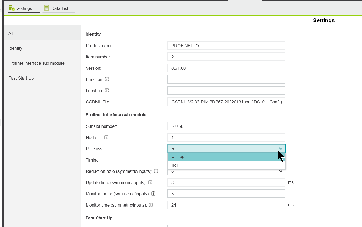
RT/IRT
Next, you need to decide which communication method is used between PDP67 and PLCNEXT, RT or IRT.Open PROFINET IO.
RT/IRT can be set from the RT Class Drop-List. In this case, RT is selected.
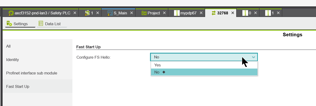
First Startup
Enables or disables the Fast Startup feature of PDP67.
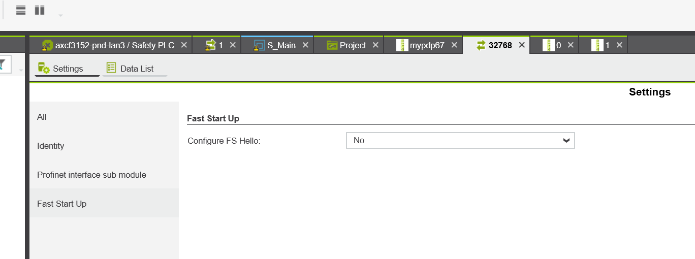
Yes/No can be set from Drop-List.
Safety
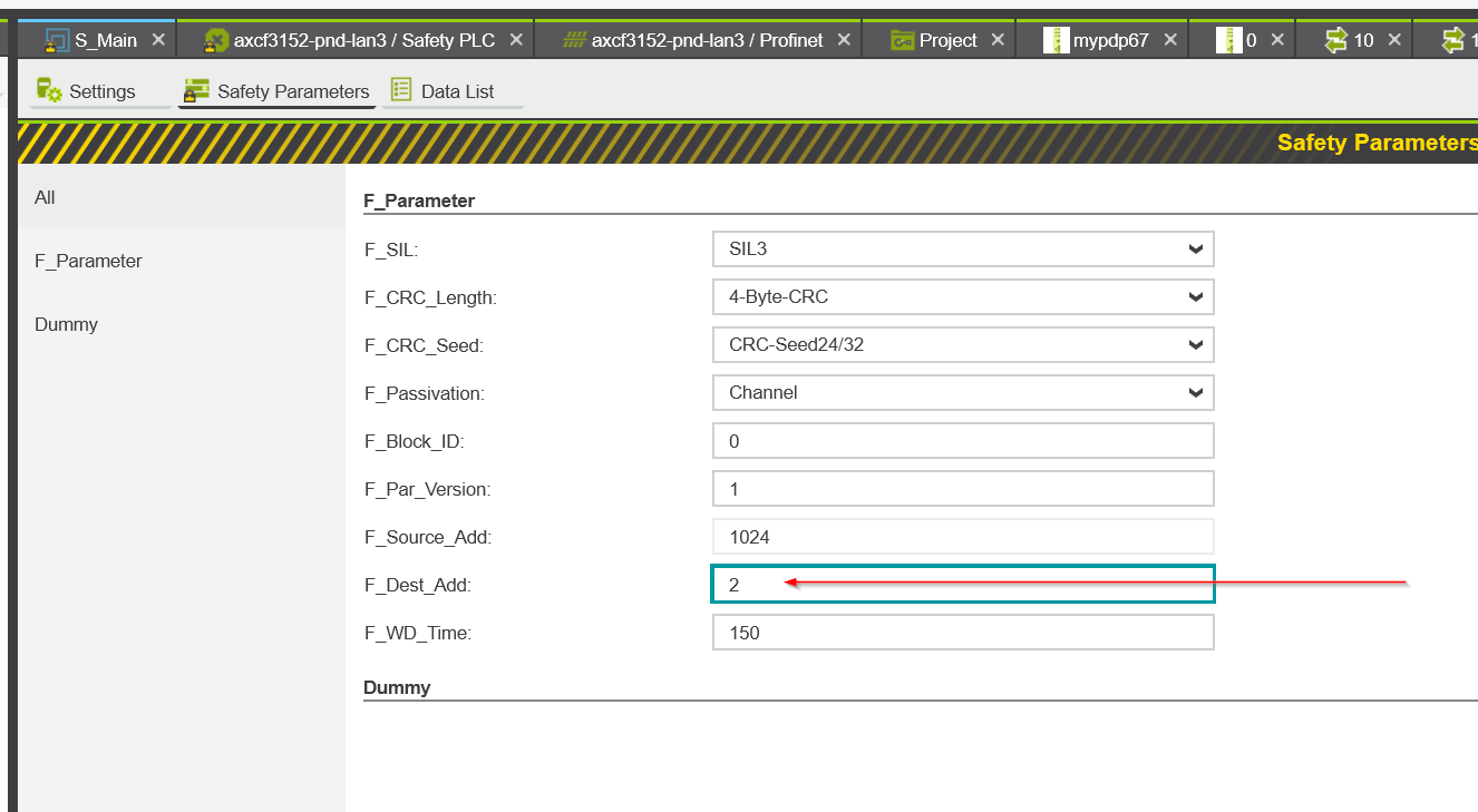
Finally, open Slot 11 to set the Safety parameter of PDP67. The yellow key ICON is the safety parameter.
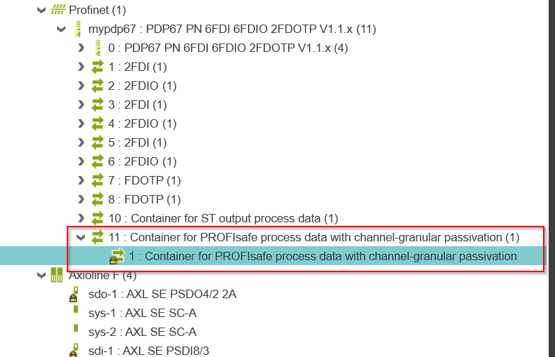
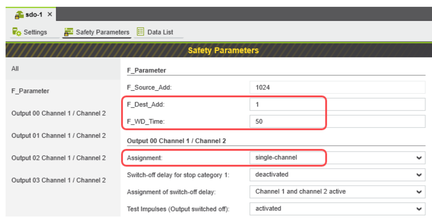
This is the Safety parameter setting screen for PDP67.
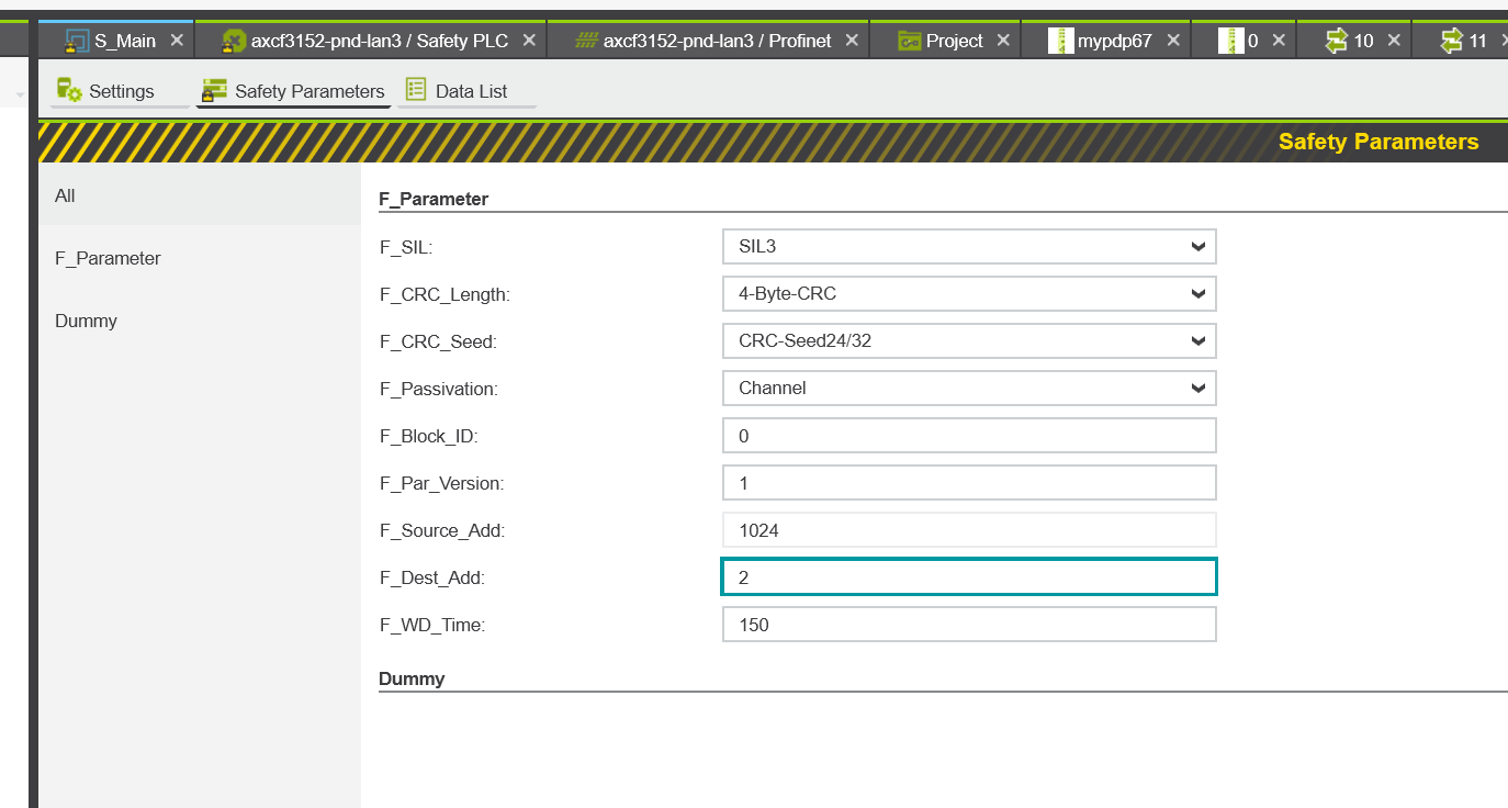
In addition to the IP address and Devices name, the F_Dest_Add is the most important factor in Profisafe communication, so enter it according to the F_Dest_Add you have just set in Pasconfig.
Check the Connectivity
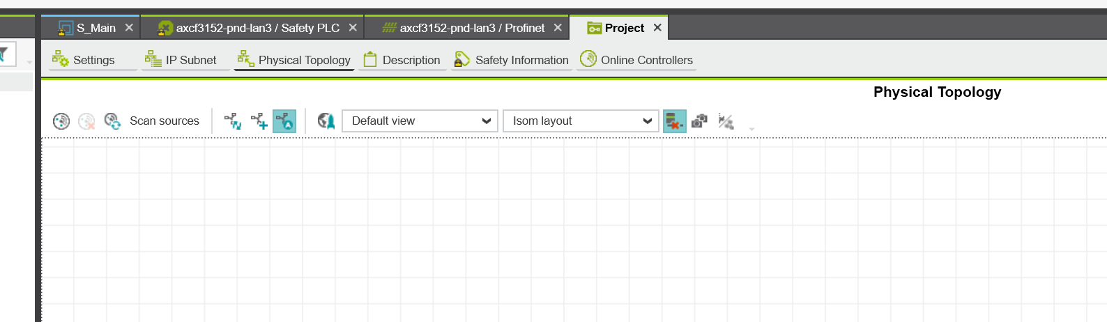
Next, let’s check the devices now on the Profinet network from the PLCNEXT Engineering tool.
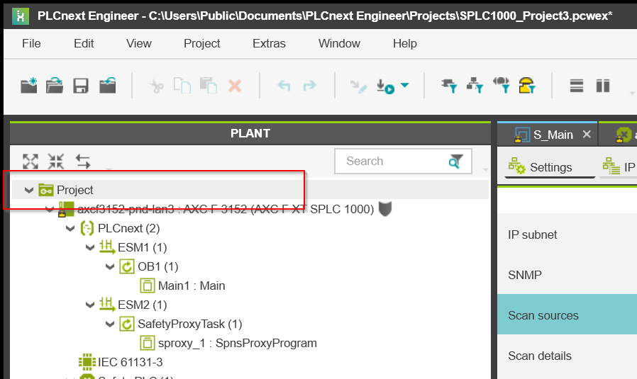
The default is the Physical Topology screen, from which you can check the status of network devices and other connections.
Scan sources Configuration
Sets parameters for device search in Scan sources.
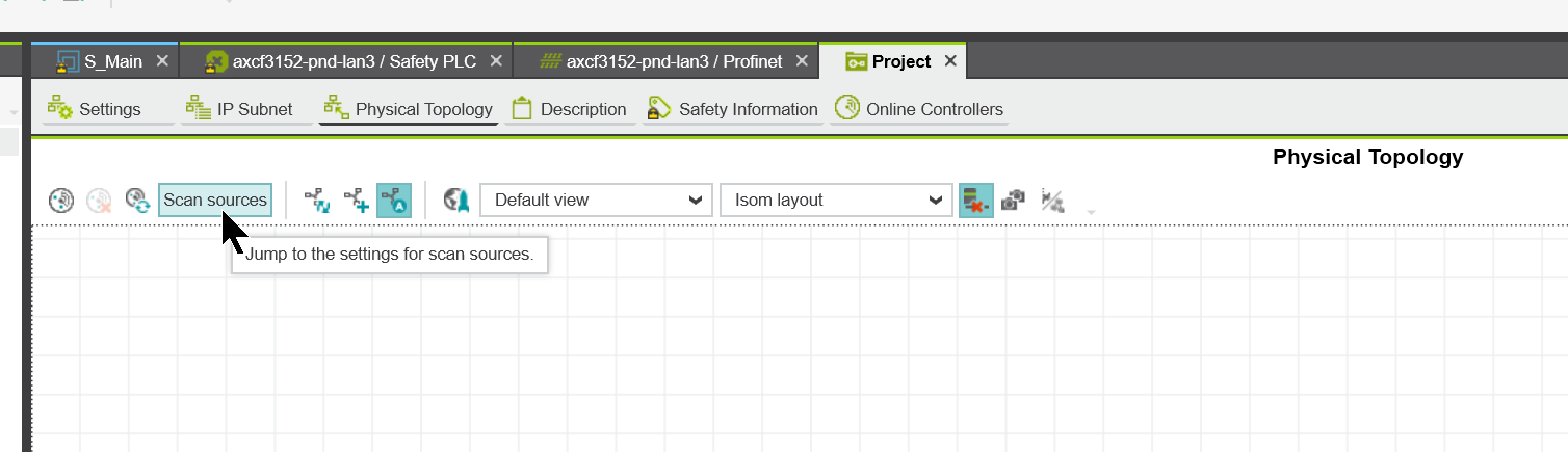
The screen will change to the Settings screen.
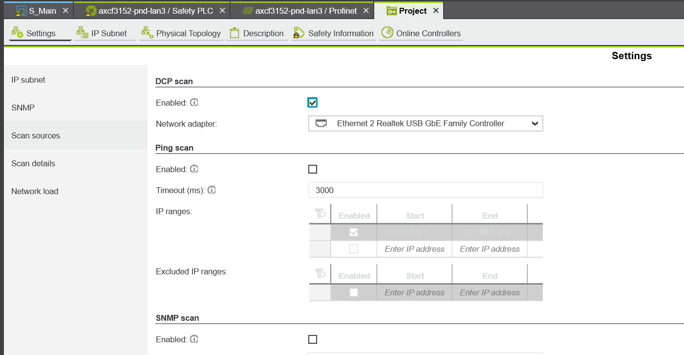
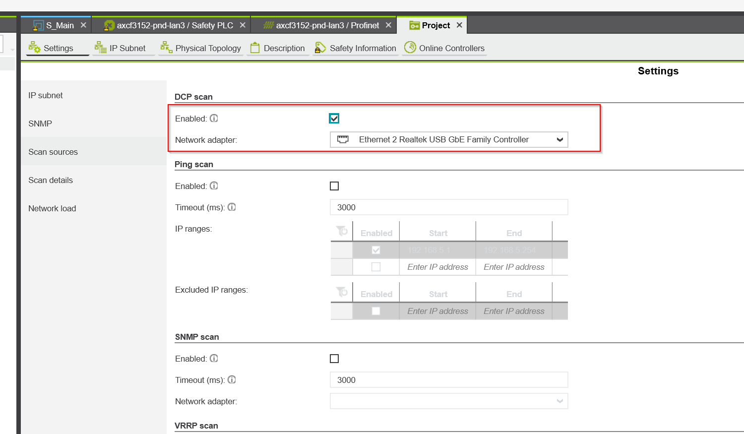
Enable DCP Scan and set up a Network Adapter that is connected to the same Profinet network as the PC on which the PLCNEXT Enginnering tool is currently installed.
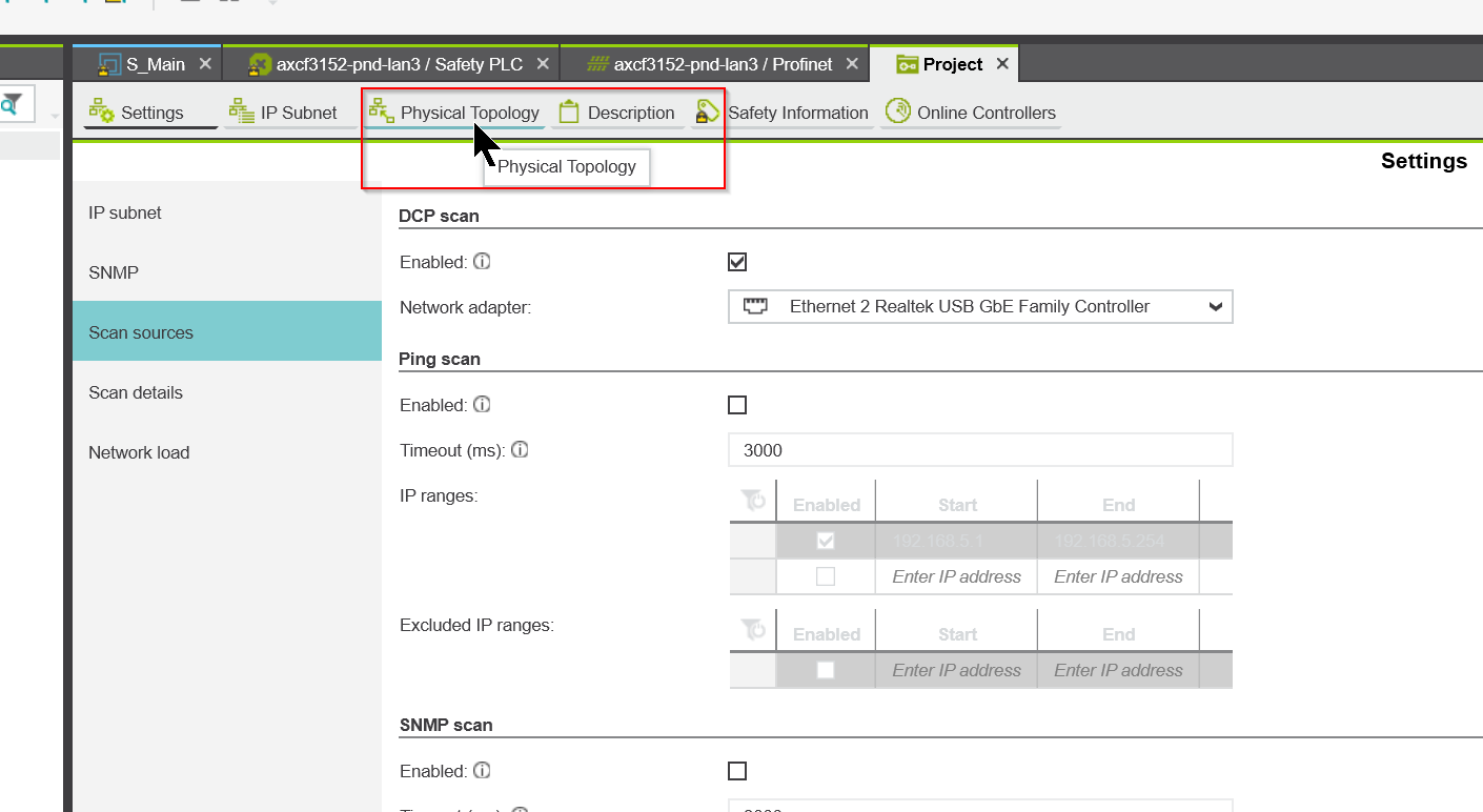
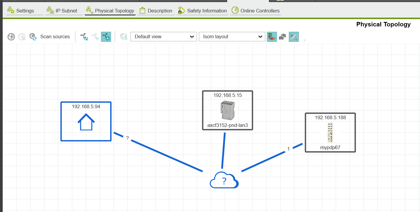
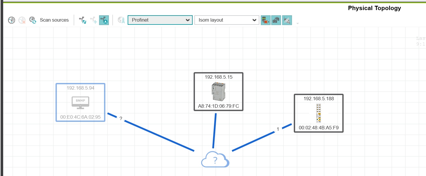
Physical Topology View
Finally, switch to Physical Topology View one more time.
Enable/Disable device graphics
The Enable/Disable device graphics function changes the ICON display for network devices.
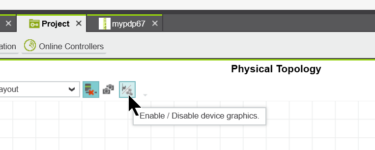
The GDSML file donwloaded from the manufacturer contains images of the equipment, so when the PLCNEXT Enginnering tool imports the GSDML file, they are imported together.
View change
Next, let’s change the View.
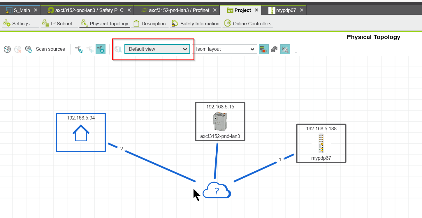
For example, let’s switch to Profinet View.
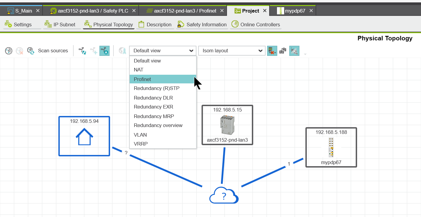
Thus, devices that are not Profinet devices turn a shallow gray color.
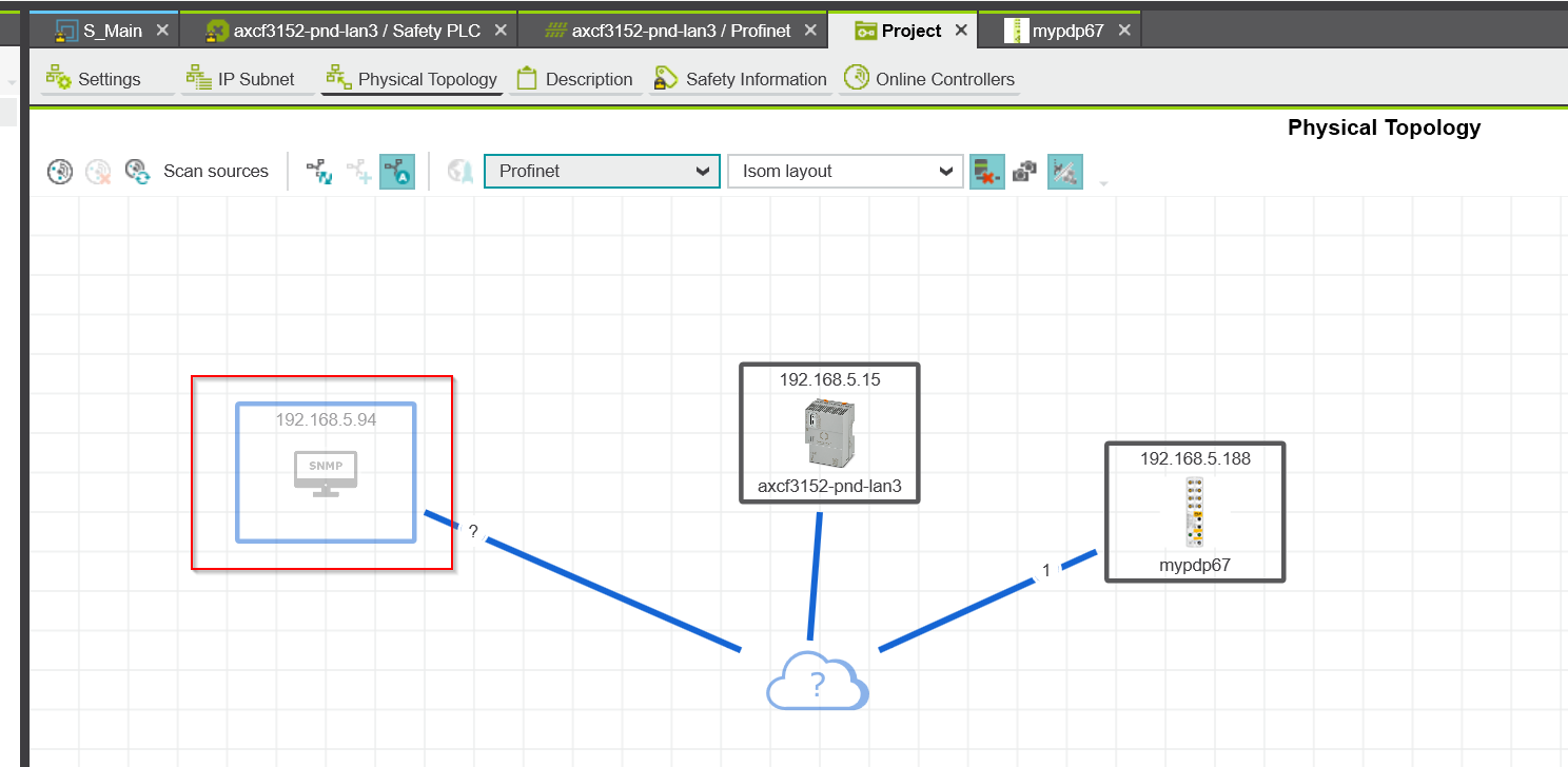
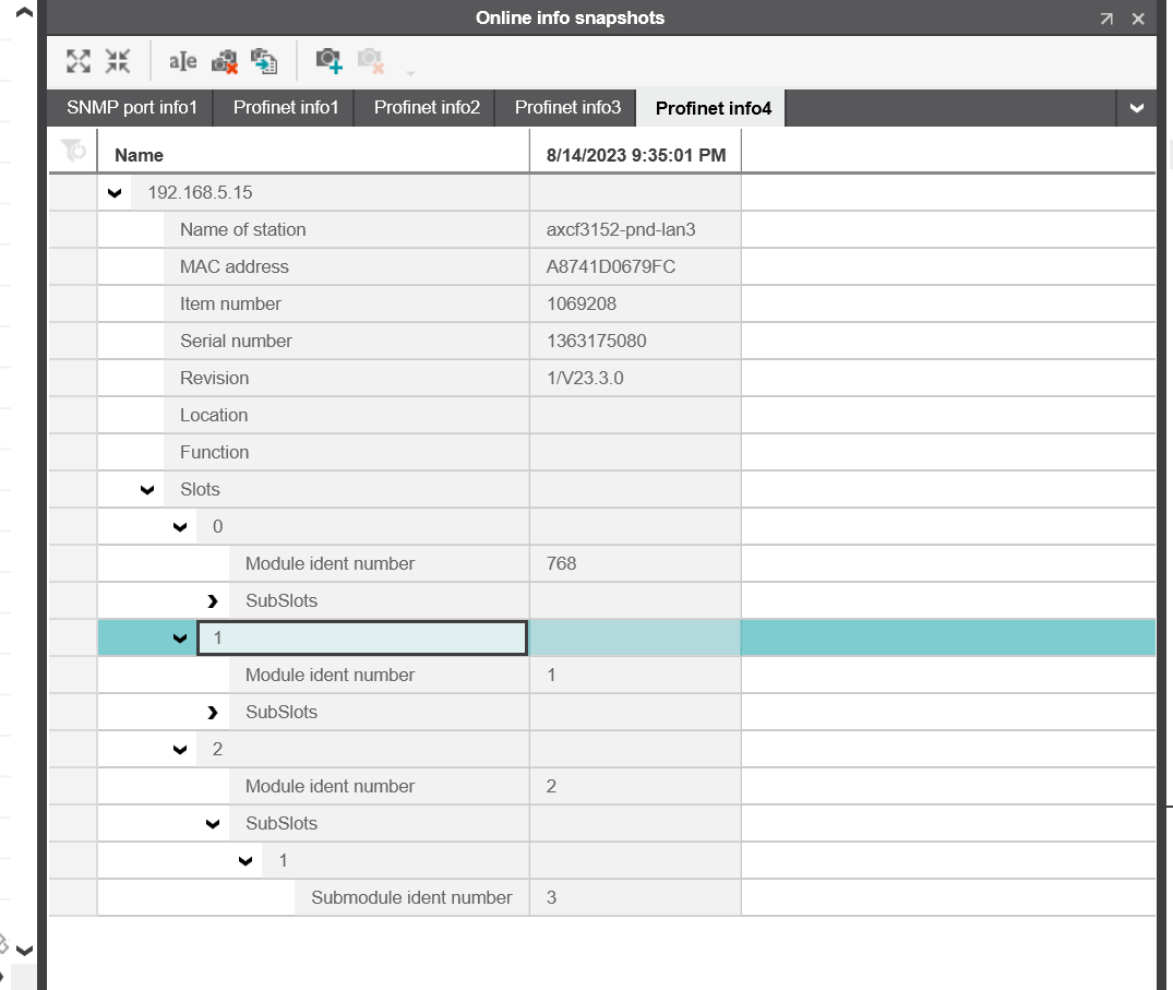
Online info snapshots
Next is the Snapshots function. This function allows you to temporarily save the network status and last settings of the device.
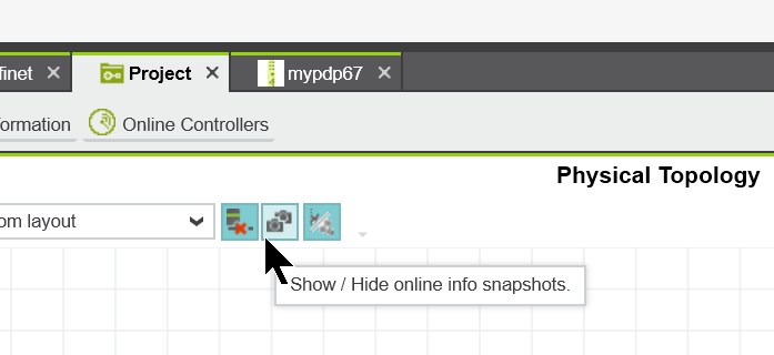
On the right is a screen called Online Info Snapshot.
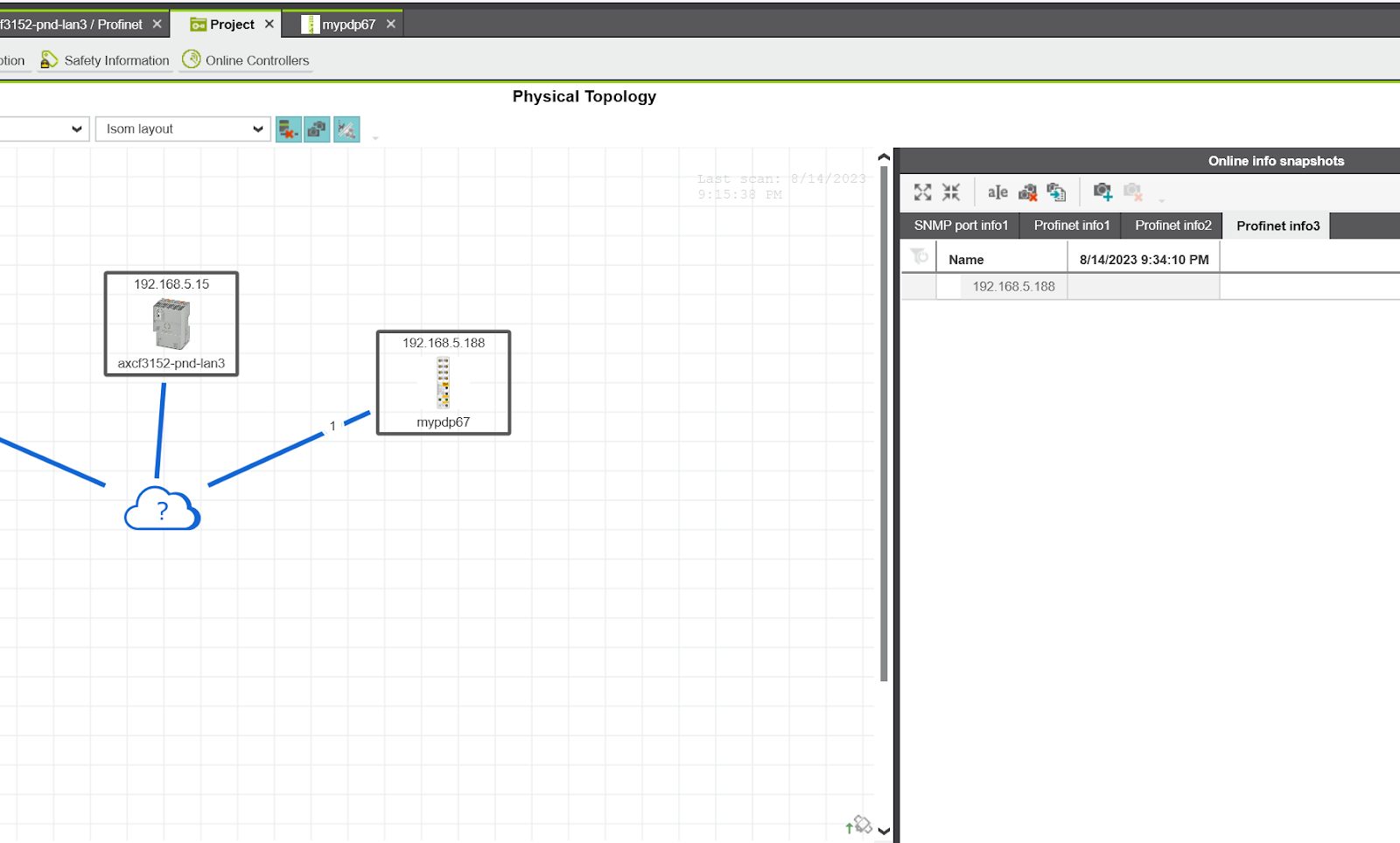
For example, right click on AXCF3152>New online info snapshot>Profinet Info to snapshot the Profinet information.
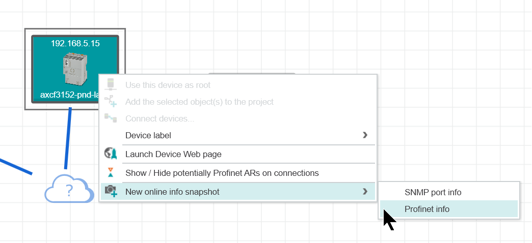
After Snapshot, Online Info will list the AXCF3152 information.
Change Display Label
Next, right-click on AXCF3152 and change the display name of the device by Device Label>Mac address.
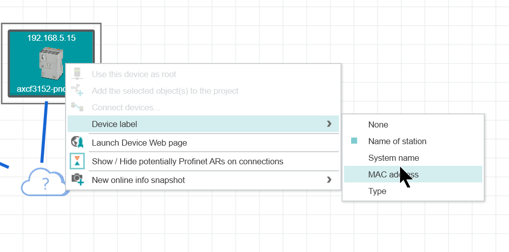
Done!
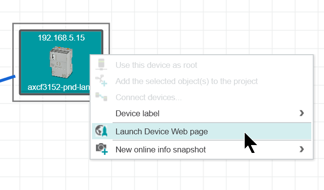
Launch Device Web page
Of course, you can start the Web Server for each device directly from the PLCNEXT Engineering tool.Right click>Launch Device Web Page.
Scan the network
Finally, use the “Scan the network” button to search for devices on the network.
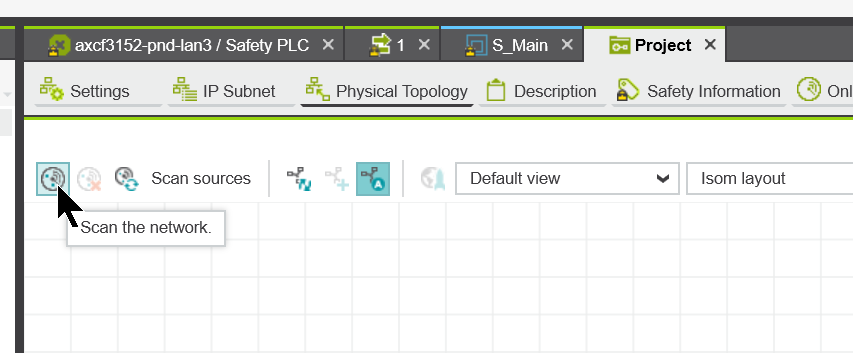
Done!AXCF3152 and PDP67 were found.
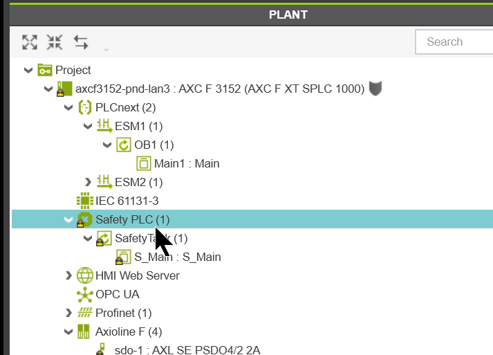
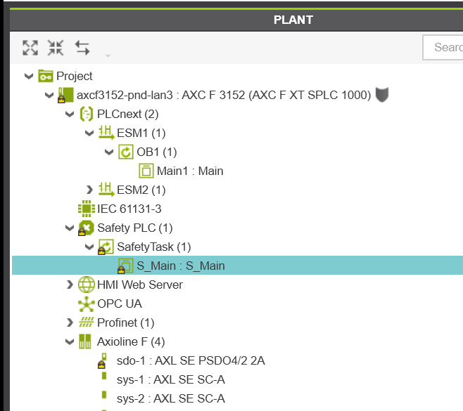
Program
Once Profinet is set up, the next step is to program it: open the Safety PLC.
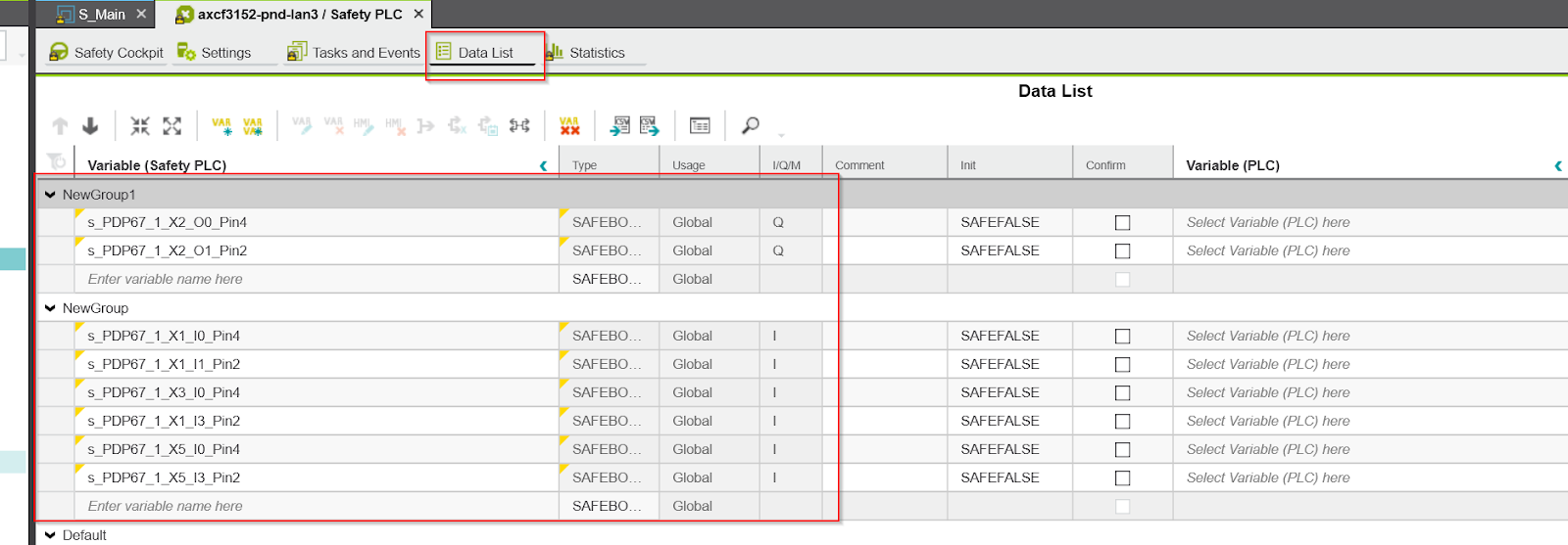
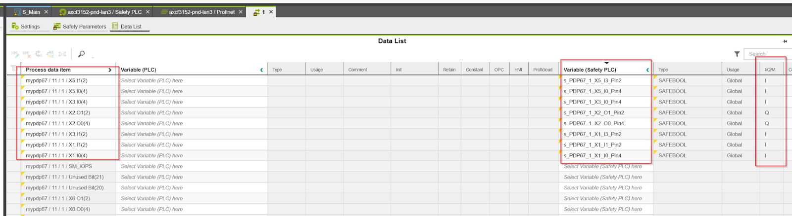
Mapping
Add a Safety variable from the Data List, and set whether the corresponding variable is an input or output in the I/Q/M columns.
Next, open Slot 11 of PDP67.
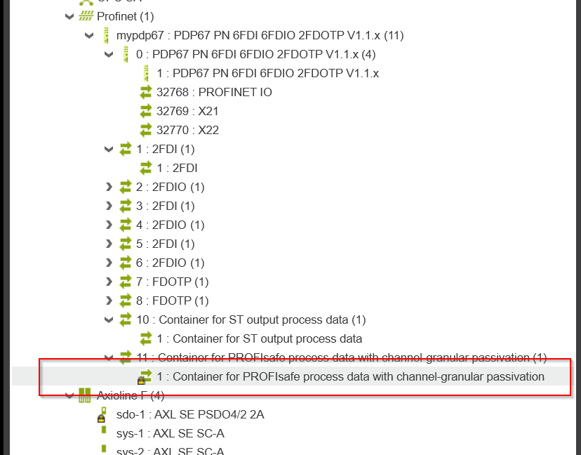
Link the Port’s Safety IO with the safety variable you just added.
S_Main
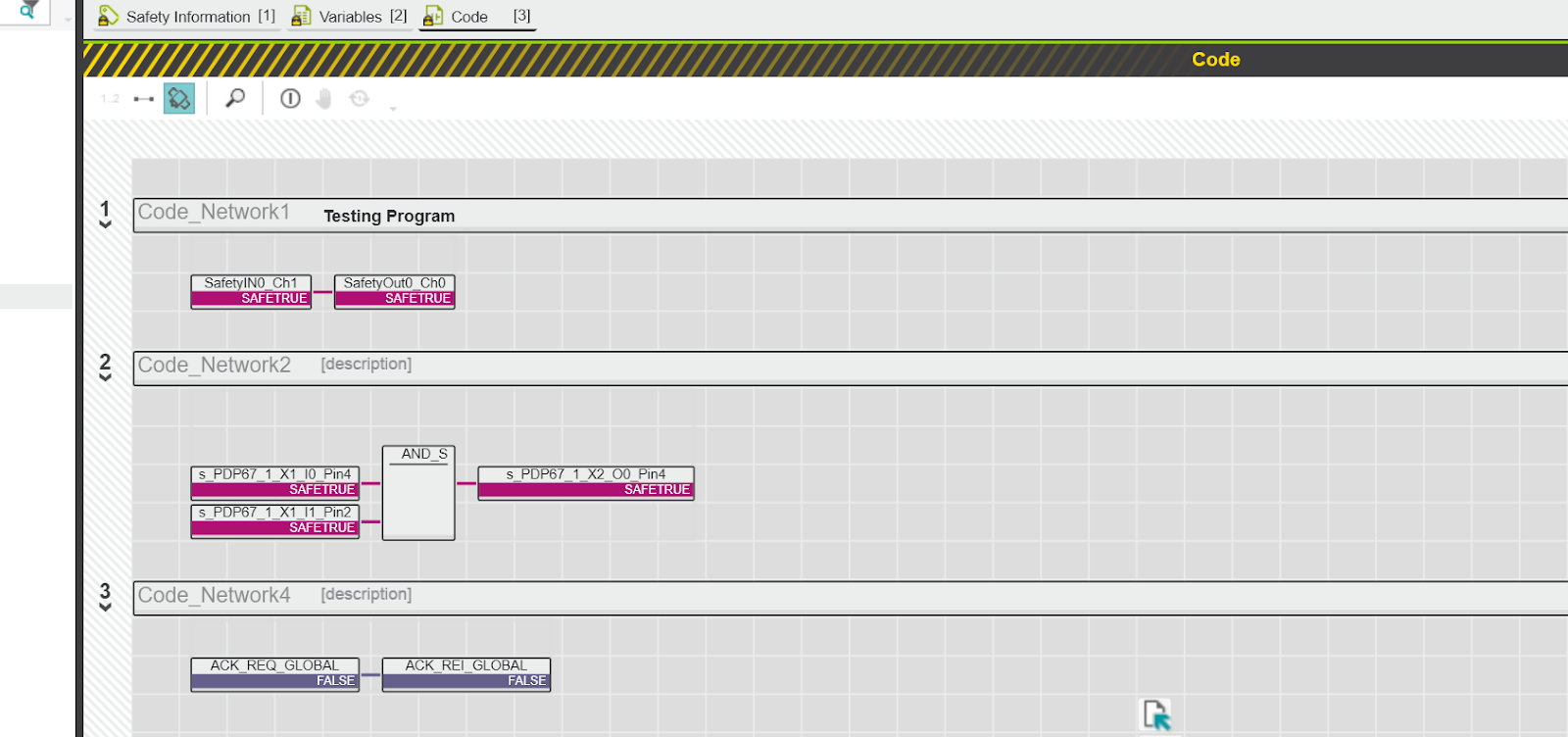
Next, add a safety program in S_Main.
Inside is just a simple program.
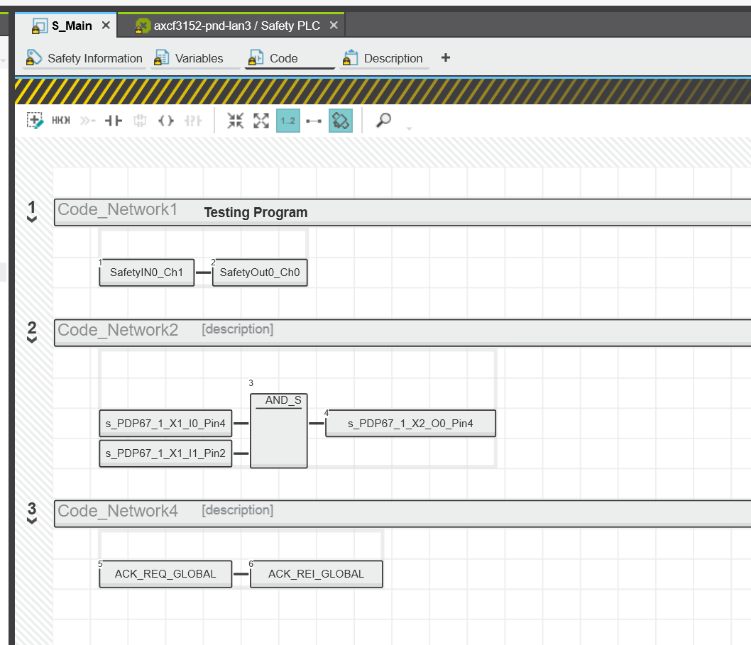
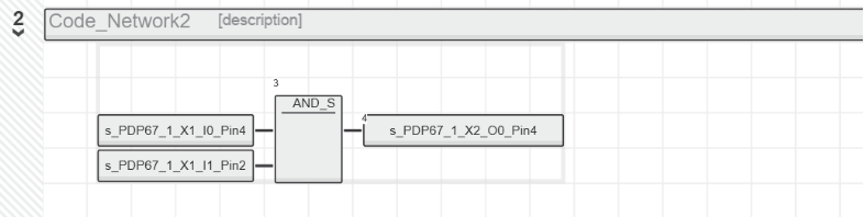
Network2
Reads the status of Pin4 and Pin2 of PortX1 of PDP67 and outputs Pin4 of PortX2 if True.
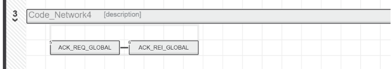
Network 3
Automatically Reset Globally.
Result
Download the project to SPLC1000 and AXCF3152.
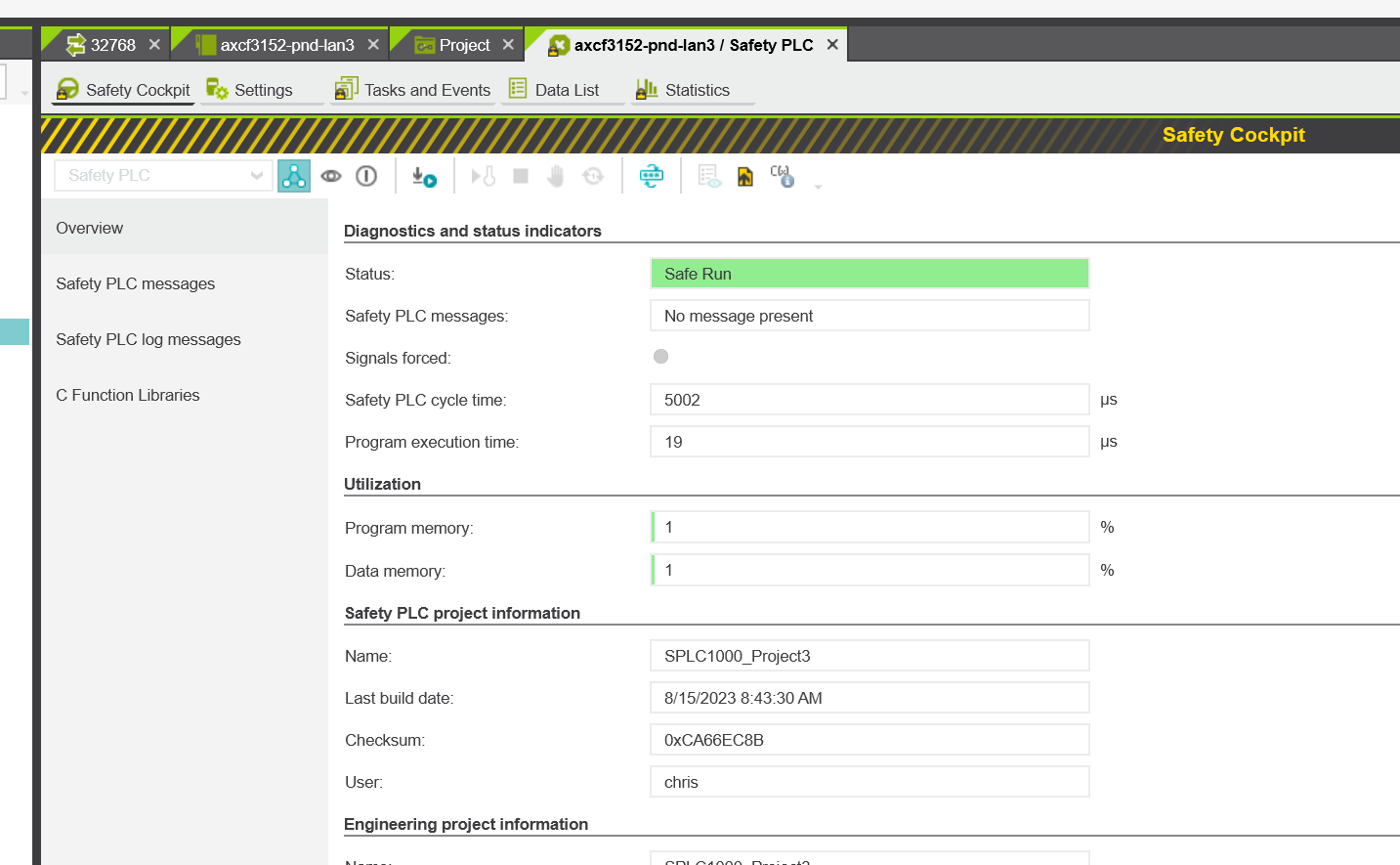
The project is now in “Safe Run” status in the Safety Cockpit, and SPLC1000 is running normally.
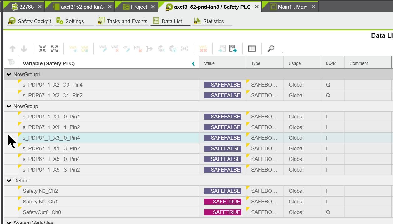
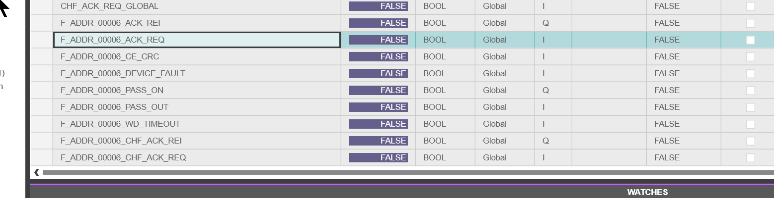
Variables mapped to PDP67 can also be monitored in the Data List.
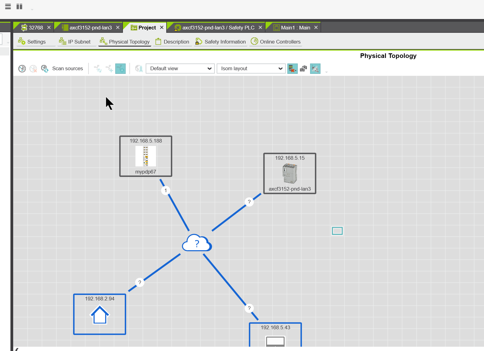
You can also check the current connection status in Physical Topology.
The safety program also outputs True on Pin 4 and Pin 2 of X1 and True on Pin 4 of X2 when the emergency stop is released.
You can also get the current state of SPLC1000 in the SPLC variable that was written in the previous description, for example:
- SPLC.EXEC_TIME:Current Cycle time
- SPLC.INFO.CYCLE_TIME:Cycle time currently set
- SPLC.INFO.TEMP:Currently SPLC1000 temperature.
- SPLC.CPU:Current SPLC1000 CPU status.
F_ADDR_0006_ACK_REQ=False, i.e. no reset request from PDP67.
You can check the operation from this Link:
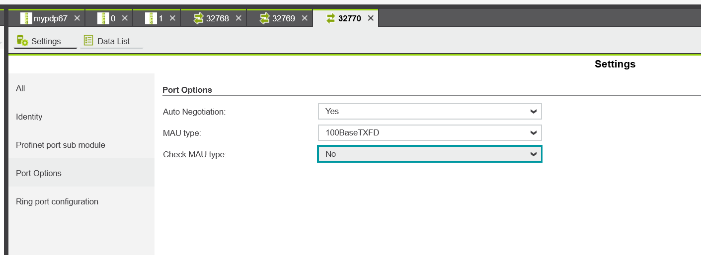
Check MAU Type
In some cases, it is necessary to remove the Check MAU Type function of the Port.
For example, disable Check MAU Type on X22.
Port Options>Check MAU Type to No.
Download
Sample projects can be downloaded from the links below.
https://github.com/soup01Threes/PLCNEXT/blob/main/SPLC1000_Connect_WithPDP67.pcwex