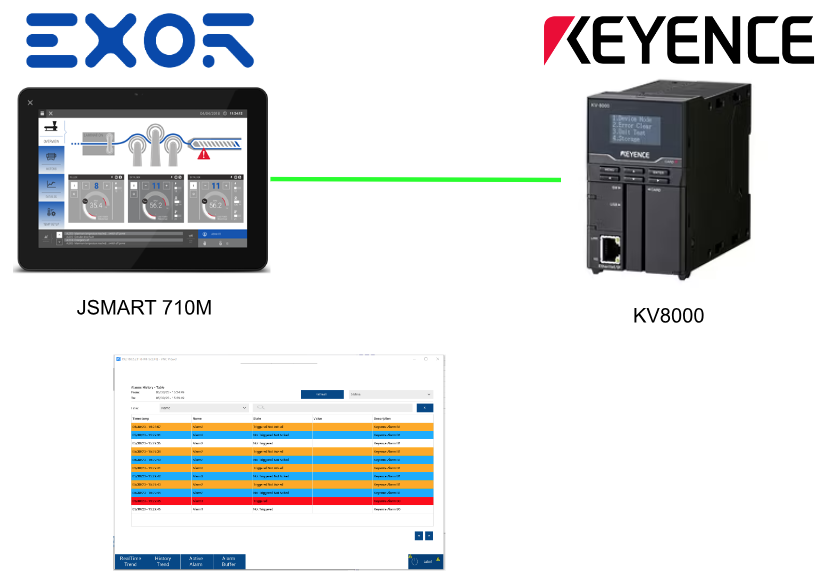
This article is about connecting an EXOR JSmart panel to a Keyence KV8000 PLC and adding Alarm Table and history display.
Let’s get started!

Reference Link
Your Target
Here is the goal this time: the EXOR panel will finally be able to display the Alarm View and Alarm History as well.
Implementation
Keyence Side
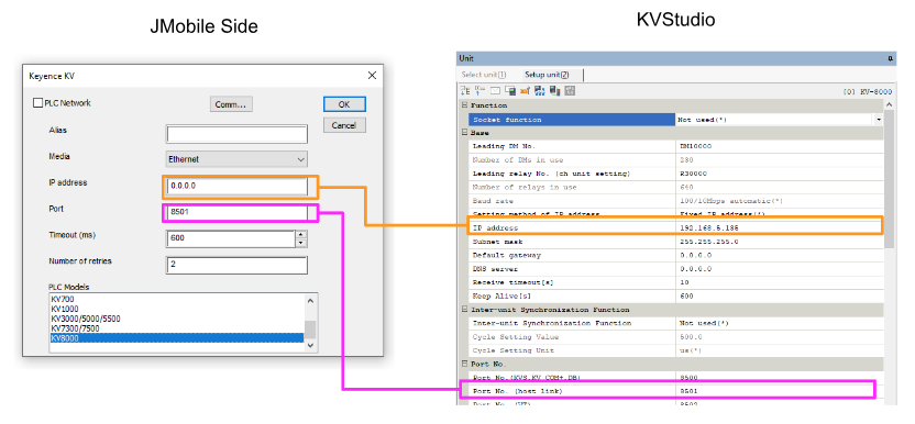
Configure the Keyence connection settings: open KV Studio>Unit Configuration>Double click on KV-8000.
Port No. (Host Link) is Default8501, which will be used later on the JMobile side.
JMobile Side
Protocols
Add Protocols by clicking Configuration>Protocols>+ button.
Select “Keyence KV” from the drop-list.
The Keyence KV connection screen appears.
PLC Models
Since KV8000 is used,please set PLC Models to KV8000.
IP Address/Port
IP address and Port should be set according to KV Studio.

So IP=192.168.5.135,Port=8051.
Done!
Tags
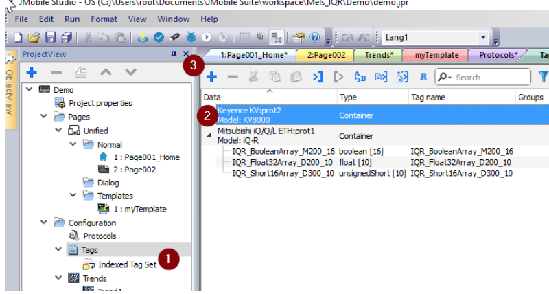
Next, add Tags by Configuration>Tags>Select the Keyence KV Protocol you just added and click the + button to add a Tag.

Data Memory(DM)
Set memorytype=Data Memory to access Keyence DM devices.Offset=100,datatype=unsignedByte[],Arraysize=8 to access 16Bit Format data from DM100 to DM107, 8 devices collectively.
Int. Utility Relay(R)
Set memorytype=Int. Utility Relay to access Keyence R devices.
Offset=0,datatype=boolean[],Arraysize=8 to access eight devices in boolean format from R0 to R7.
Link Relay(B)
Set memorytype=Link Relay to access the Keyence B device.
Offset=0,datatype=boolean[],Arraysize=16 to access B0 to boolean Format, 16 devices collectively.
Done!
Alarm
The alarm function is a feature of all manufacturers and will be introduced in the next Section.
ADD
Set a new alarm by pressing the Alarms>+ button.
Sets the device that triggers the Alarm message.
Let’s use Link Relay B0 and B1 this time.
Add New Group
Create Alarm Groups, which allow you to set up alarm groups with detailed settings for what kind of alarms you want to store, etc. Double-click on Groups.
The Groups configuration screen is now displayed. Click <new> to add a New Group.
This time two alarms were added to the “KeyenceStation” Group.
Ack
The Ack CheckBox can be set to require operator acknowledgement to clear the corresponding alarm. In this example, B0 is set to “no acknowledge” and B1 is set to “acknowledge required” to introduce the function.
Alarm Color
The EXOR panel can change the display color depending on the alarm status. Select the alarm to be changed and click on Color in Properties on the right.
You can set the text color (Foreground) and message background color (Background) for alarm messages.
A brief summary of the color settings for each condition is as follows,
- Red=Triggered=Trigger conditions for the corresponding alarm were met.
- Orange=Trigger Not Acknowledged=Trigger condition for the corresponding alarm has been met.
- Blue=Not Triggered Not Acknowledged=Trigger condition for the corresponding alarm was met > then failed again, but not Acknowledged
- Green=Triggered Acknowledge=Trigger condition for the corresponding alarm has been met, Acknowledged
Apply colors to all alarms to activate the setting in all alarms.
Add Alarm View
Add an Alarm View to the screen by Basic>Alarms>Active alarm table.
Done!
Edit
Double-click on the Alarm View to change the Layout.
Properties on the right allows for detailed settings, but basically Default is OK.
Result
Here is the result. There are no alarms now, and of course nothing is displayed.
Select “Show all” from the drop-list at the bottom left.
Alarms that are not currently triggered can also be listed.
B0=True. Now the color turns red.
B0=False and the Alarm Message disappeared in the Alarm View. This is because there was no ACK Checked in the Checkbox of B0.
Now set device B1 to True, and the Alarm Message color is now Orange. This is because Orange is a setting that has been Triggered but not Acked. So, alarms that are set to require Ack will not turn red. (Since the Triggered condition is not hit either.)
Now press the Ack button for the B1 alarm, and the Alarm Message turns green. At that time, B1 was still True.
When B1 was Acked and returned to False, the Alarm message disappeared from the Alarm view.
Finally, Change B1 from True to False B1 again, but when it was not Acked, the Alarm Message turned blue.
Description
So far, nothing has been shown in the Description in the Alarm View.
Just open Configuration>Alarms and enter the text at the actual Description.
Done!
The Description is now displayed in the Alarm View.
Alarm Buffer
Alarm Buffer is also a feature that every HMI manufacturer has, i.e., the ability to store alarms, and was set to Default in Configuration>Events Buffer.
Add View
Go to Basic>Alarms and Add Alarm history table.
Done!
The Alarm History View records and displays the time of all alarm state transitions.
Result
Done!